EP0769735B1 - Motion tracking apparatus for driverless vehicle - Google Patents
Motion tracking apparatus for driverless vehicle Download PDFInfo
- Publication number
- EP0769735B1 EP0769735B1 EP96116811A EP96116811A EP0769735B1 EP 0769735 B1 EP0769735 B1 EP 0769735B1 EP 96116811 A EP96116811 A EP 96116811A EP 96116811 A EP96116811 A EP 96116811A EP 0769735 B1 EP0769735 B1 EP 0769735B1
- Authority
- EP
- European Patent Office
- Prior art keywords
- vehicle
- caster
- sensor
- wheel
- navigation
- Prior art date
- Legal status (The legal status is an assumption and is not a legal conclusion. Google has not performed a legal analysis and makes no representation as to the accuracy of the status listed.)
- Expired - Lifetime
Links
- 238000005259 measurement Methods 0.000 claims description 6
- 238000000034 method Methods 0.000 claims description 4
- 238000013519 translation Methods 0.000 description 12
- 238000013461 design Methods 0.000 description 4
- 238000013459 approach Methods 0.000 description 3
- 235000004443 Ricinus communis Nutrition 0.000 description 2
- 238000010001 crabbing Methods 0.000 description 2
- 238000004891 communication Methods 0.000 description 1
- 230000001010 compromised effect Effects 0.000 description 1
- 238000010276 construction Methods 0.000 description 1
- 238000012937 correction Methods 0.000 description 1
- 230000003247 decreasing effect Effects 0.000 description 1
- 230000001419 dependent effect Effects 0.000 description 1
- 230000003287 optical effect Effects 0.000 description 1
- 238000005070 sampling Methods 0.000 description 1
- 238000005201 scrubbing Methods 0.000 description 1
- 239000007787 solid Substances 0.000 description 1
Images

Classifications
-
- G—PHYSICS
- G05—CONTROLLING; REGULATING
- G05D—SYSTEMS FOR CONTROLLING OR REGULATING NON-ELECTRIC VARIABLES
- G05D1/00—Control of position, course, altitude or attitude of land, water, air or space vehicles, e.g. using automatic pilots
- G05D1/02—Control of position or course in two dimensions
- G05D1/021—Control of position or course in two dimensions specially adapted to land vehicles
- G05D1/0268—Control of position or course in two dimensions specially adapted to land vehicles using internal positioning means
- G05D1/027—Control of position or course in two dimensions specially adapted to land vehicles using internal positioning means comprising intertial navigation means, e.g. azimuth detector
-
- G—PHYSICS
- G05—CONTROLLING; REGULATING
- G05D—SYSTEMS FOR CONTROLLING OR REGULATING NON-ELECTRIC VARIABLES
- G05D1/00—Control of position, course, altitude or attitude of land, water, air or space vehicles, e.g. using automatic pilots
- G05D1/02—Control of position or course in two dimensions
- G05D1/021—Control of position or course in two dimensions specially adapted to land vehicles
- G05D1/0268—Control of position or course in two dimensions specially adapted to land vehicles using internal positioning means
- G05D1/0272—Control of position or course in two dimensions specially adapted to land vehicles using internal positioning means comprising means for registering the travel distance, e.g. revolutions of wheels
Definitions
- This invention relates to a vehicle navigation and guidance system comprising an apparatus for measuring and accounting for the lateral movement of the vehicle and a method of guiding a vehicle using the same. More particularly, this invention relates to a swivel caster fitted with rotational and swivel angle measurement sensors mounted to a driverless vehicle so that the lateral motion of the vehicle can be detected and accounted for by the vehicle's navigation and guidance system.
- GB-A-2,158,965 and U S 4,847,769 both describe vehicles in which the movement is predicted by a dead reckoning system which determines the position of the vehicle at any given time by sensing the steering angle and the angle of rotation of a controlled steering caster during a short time interval.
- U S 4,847,769 further describes a system where the predicted position is frequently checked and corrected against an actual position determined by a vehicle mounted laser scanning and reference frame mounted target system.
- U S 4,816,998 discusses a vehicle that uses a caster wheel having both an angle measuring sensor and a wheel rotation measuring sensor for enabling the navigation and guidance system to calculate a mean distance traveled, a change in angle of an axis on the vehicle and vehicle heading change assuming ideal travel along a fixed radius arcuate path.
- U S 5,175,415 discusses an apparatus for measuring the forward and reverse movement of a vehicle by placing a separate encoder wheel adjacent to each non-pivoting drive wheel.
- US 5,058,023 discloses a vehicle position determining apparatus which calculates the position of the vehicle from the measurements of two separate wheel sensors measuring the distance travelled and/or changes in vehicle heading and two further independent reference points, namely a reading from a global positioning system and an electronic or magnetic compass.
- All of the navigation and guidance systems heretofore are limited because none of these systems determine their current position by measuring and accounting for the lateral movement of the vehicle.
- the lateral movement of the vehicle is often referred to as crabbing, scrubbing or side slip.
- the lateral movement of the vehicle is determined with respect to the vehicle's pivot point. This is typically a location along the longitudinal centerline of the vehicle that the navigation and guidance system attempts to direct along the selected path.
- a vehicle may experience lateral motion for a variety of reasons, for instance, when the vehicle is: i) misaligned, ii) turned, where the wheels pivot, distort and/or slip, and iii) intentionally steered laterally. Accordingly, the overall tracking accuracy of the systems heretofore is compromised by their inability to measure and account for the lateral movement component in the vehicle's change of position.
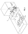
- FIG. 1 is a perspective view of a dual-end steering driverless vehicle equipped with a track wheel caster in accordance with the present invention.
- FIG. 2a is a perspective view of a track wheel caster assembly in accordance with the preferred embodiment of the present invention.
- FIG. 2b is a side view of the track wheel caster assembly depicted in FIG. 2a.
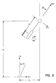
- FIG. 3 is a diagrammatical representation of a vehicle equipped with a track wheel caster in accordance with the preferred embodiment of the present invention.
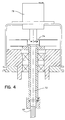
- FIG. 4 is a cross-sectional view of an absolute encoder fitted with an electric slip ring assembly in accordance with the preferred embodiment of the present invention.
- a preferred embodiment of the present invention is a driverless vehicle comprising a navigation and guidance system having an angular motion sensor and a track wheel caster assembly equipped with a caster pivot sensor and a wheel rotation sensor to determine the relative position of the vehicle by taking into account substantially all movement of the vehicle along the surface upon which the vehicle is travelling.
- These sensors enable the navigation system to more accurately determine the vehicle's current position and enable the guidance system to guide the vehicle.
- FIG. 1 depicts a dual-end steering driverless vehicle 10 comprising a navigation and guidance system equipped with an angular motion sensor 12 , a track wheel caster assembly 40 , at least one computer processor 16 , and a front and a rear steering mechanism 18 and 20 , respectively.
- vehicle 10 can be any vehicle suitable for this purpose including but not limited to driverless, single-end or dual-end steered, wire and non-wire guided vehicles.
- the computer processor and steering mechanism may be of any conventional type known to be used for this purpose.
- the angular motion sensor is employed to supply information about the current heading of the vehicle.
- the angular motion sensor is a gyroscope which may be any type of gyroscope suitable for this purpose and may be selected to suit the particular application.
- the gyroscope will be of the solid state rate gyroscope type.
- the track wheel caster assembly 40 as best depicted in FIGs. 2(a&b), comprises: a free wheeling contact wheel 42 , a mounting plate 44 , a freely pivoting castor sub-assembly 46 , a wheel rotation sensor 48 , and a caster pivot sensor 50 .
- the design of the track wheel caster assembly 40 will depend on the particulars of the application but the design criteria should attempt to optimize the traction of the contact wheel 42 while minimizing its pivot friction.
- the contact wheel 42 may be fitted with a tire 52 to achieve better contact properties.
- a soft tire provides better traction while a harder tire results in lower pivot friction. Therefore, a tire having characteristics that compromise between these two competing factors is preferred.
- the tread profile of the tire 52 may be selected based on the specifics of a particular application, a preferred tread profile is spherically shaped to distribute wheel loading symmetrically about the contact point.
- the freely pivoting castor sub-assembly 46 typically comprises a horizontal offset, sometimes referred to as a "caster offset” or “caster lead", between the caster stem 64 and the contact wheel axle 66 .
- This horizontal offset reduces the force required to cause the caster to pivot.
- the sub-assembly 46 can optionally be adapted with a spring loaded pivot joint 68 and fork 70 that joins the contact wheel 42 to the sub-assembly in a manner which enables the contact wheel 42 to move up and down with respect to the mounting plate 44 to allow the contact wheel 42 to accommodate undulations in the surface.
- the wheel rotation sensor 48 may be any device that provides a signal responsive to the rotational movement of the contact wheel which may include optical, magnetic, electro-mechanical sensors or the like.
- the wheel rotation sensor 48 is an incremental shaft encoder positioned about the contact wheel axle 66 . More preferably, the incremental shaft encoder will be of the quadrature type which additional provides the direction of rotation.
- the caster pivot sensor 50 may be any device that provides a signal responsive to the rotational movement of the caster sub-assembly 46 with respect to the caster mounting plate 44 .
- the caster pivot sensor 50 is an absolute shaft encoder, as depicted in FIG. 4, positioned on the caster stem 64 . An absolute shaft encoder provides a signal identifying the absolute position of the measured shaft.
- the caster stem 64 and the absolute shaft encoder will have a hollow shaft 72 and the body of the absolute encoder will have an opening through the center axis of the body 74 leading up to an electric slip ring assembly 76 , as shown in FIG. 4, to accommodate signal wires from the wheel rotation sensor 48 .
- An electric slip ring is a device that maintains electrical communication between connections on a first member, commonly referred to as the rotor, that rotates with respect to a second member, commonly referred to as the stator, and corresponding connection on the second member.
- the signal wires from the wheel rotation sensor 48 will be routed through the hollow caster stem 64 , the absolute encoder shaft 72 , the body of the encoder 74 and connected to the rotor side of the slip ring assembly 76 .
- the signal from the wheel rotation sensor 48 can be communicated to the navigation and guidance system in a variety of ways dependent on the design of the vehicle, this preferred configuration allows unlimited caster pivot rotation in either direction.
- FIGs 2(a&b) The functioning of a vehicle adapted with a track wheel caster assembly, as depicted in FIGs 2(a&b), in accordance with a preferred embodiment of the present invention can be described as follows and best understood by referencing FIG. 3.
- the vehicle's navigation and guidance system on the vehicle operates in a conventional manner by sampling data from various sensors at short time intervals and steering the vehicle responsive to information received from these inputs. More specifically, the navigation and guidance system attempts to guide a point on the vehicle designated as the pivot point P along a selected path or toward a designated location.
- the pivot point P is typically a location along the longitudinal centerline of the vehicle. The selection of this point may be determined from the design and/or dynamics of the vehicle.
- the pivot point P is used as a reference point or origin for calculating vehicle movement with respect to the vehicle's coordinate system, often referred to as vehicle frame reference.
- the calculations of Ym , that component of the vehicle's change of position in the for and aft direction (Y-direction), and Xm , that component of the vehicle's change of position in the lateral direction (X-direction), are all referenced to an X,Y coordinate system having the pivot point P as the origin.
- the track wheel caster assembly is mounted at any arbitrary or convenient location on the vehicle.
- the position of the caster assembly, specifically the center of the caster pivot axis 64 , relative to the pivot point is measured.
- the measured distance between the two points is recorded as Cy the distance in the Y-direction and Cx the distance in the X-direction both with respect to the vehicle's frame of reference.
- the radius Wr of the caster's contact wheel 42 with tire 52 and the distance S1 of the horizontal offset are measured and recorded. These constants are used as part of the calculation of Ym and Xm .
- the wheel rotation sensor 48 and/or the caster pivot sensor 50 will sense the motion and transmit a corresponding signal to the navigation and guidance system's computer processor 16 .
- the motion of the vehicle Rm as sensed by the wheel rotation sensor 48 , is the product of the wheel rotation angle Wa , in radians, determined directly from information supplied by the wheel rotation sensor and the wheel radius Wr .
- the motion of the vehicle Pm as sensed by the caster pivot sensor 50 , is the product of the change in the pivot angle (final angle Sf minus initial angle Si ) of the caster less the vehicle's heading change Hc , as determined from the angular motion sensor, and the distance of the caster's horizontal offset S1 .
- the average caster angle SA between two measuring intervals is the initial angle Si plus half the change in the pivot angle over the measurement interval.
- Xm and Ym are then used by the navigation and guidance system to calculate the vehicle's current location so that the guidance system can determine how to direct the vehicle along a desired path or toward a desired location.
- Caster translation continues indefinitely as SA approaches 180 deg. A practical limit is defined by the resolution of the caster pivot encoder. Caster translation is complete when the caster pivot angle measures 180 deg.
- Caster translation continues indefinitely as SA approaches (+ or -) 90 deg. Practical caster translation is complete when the caster pivot sensor measures (+ or -) 90 deg.
Landscapes
- Engineering & Computer Science (AREA)
- Radar, Positioning & Navigation (AREA)
- Remote Sensing (AREA)
- Aviation & Aerospace Engineering (AREA)
- Physics & Mathematics (AREA)
- General Physics & Mathematics (AREA)
- Automation & Control Theory (AREA)
- Navigation (AREA)
- Control Of Position, Course, Altitude, Or Attitude Of Moving Bodies (AREA)
- Vehicle Body Suspensions (AREA)
- Steering Control In Accordance With Driving Conditions (AREA)
Priority Applications (1)
| Application Number | Priority Date | Filing Date | Title |
|---|---|---|---|
| EP00126196A EP1102140B1 (en) | 1995-10-18 | 1996-10-18 | Motion tracking apparatus for driverless vehicle |
Applications Claiming Priority (4)
| Application Number | Priority Date | Filing Date | Title |
|---|---|---|---|
| US554095P | 1995-10-18 | 1995-10-18 | |
| US5540 | 1995-10-18 | ||
| US713539 | 1996-09-13 | ||
| US08/713,539 US5916285A (en) | 1995-10-18 | 1996-09-13 | Method and apparatus for sensing forward, reverse and lateral motion of a driverless vehicle |
Related Child Applications (1)
| Application Number | Title | Priority Date | Filing Date |
|---|---|---|---|
| EP00126196A Division EP1102140B1 (en) | 1995-10-18 | 1996-10-18 | Motion tracking apparatus for driverless vehicle |
Publications (3)
| Publication Number | Publication Date |
|---|---|
| EP0769735A2 EP0769735A2 (en) | 1997-04-23 |
| EP0769735A3 EP0769735A3 (en) | 1998-05-20 |
| EP0769735B1 true EP0769735B1 (en) | 2002-06-12 |
Family
ID=26674469
Family Applications (1)
| Application Number | Title | Priority Date | Filing Date |
|---|---|---|---|
| EP96116811A Expired - Lifetime EP0769735B1 (en) | 1995-10-18 | 1996-10-18 | Motion tracking apparatus for driverless vehicle |
Country Status (11)
| Country | Link |
|---|---|
| US (1) | US5916285A (zh) |
| EP (1) | EP0769735B1 (zh) |
| JP (1) | JPH10307030A (zh) |
| CN (2) | CN1182982C (zh) |
| AU (1) | AU708305B2 (zh) |
| BR (1) | BR9605158A (zh) |
| CA (1) | CA2188078C (zh) |
| DE (2) | DE69621738T2 (zh) |
| ES (1) | ES2178690T3 (zh) |
| HU (1) | HUP9602855A3 (zh) |
| PL (1) | PL316549A1 (zh) |
Families Citing this family (83)
| Publication number | Priority date | Publication date | Assignee | Title |
|---|---|---|---|---|
| DE19734247A1 (de) * | 1997-08-07 | 1999-02-11 | Litef Gmbh | Driftsensor für Landfahrzeuge |
| AU2449299A (en) | 1997-12-17 | 1999-07-05 | James C. O'meara | Laser lighting system |
| IL145680A0 (en) | 2001-09-26 | 2002-06-30 | Friendly Robotics Ltd | Robotic vacuum cleaner |
| AU2002341358A1 (en) * | 2001-09-26 | 2003-04-07 | Friendly Robotics Ltd. | Robotic vacuum cleaner |
| DE60214761T2 (de) * | 2001-12-12 | 2006-12-28 | Jervis B. Webb International Co., Farmington Hills | Leitsystem und Verfahren für fahrerloses Fahrzeug |
| US7100725B2 (en) | 2002-08-30 | 2006-09-05 | Aethon | Robotic cart pulling vehicle |
| US8075243B2 (en) | 2004-05-03 | 2011-12-13 | Jervis B. Webb Company | Automatic transport loading system and method |
| JP2007536177A (ja) * | 2004-05-03 | 2007-12-13 | ジエービス・ビー・ウエブ・インターナショナル・カンパニー | 積荷を搬送体に自動的に積込むシステム及び方法 |
| US7980808B2 (en) * | 2004-05-03 | 2011-07-19 | Jervis B. Webb Company | Automatic transport loading system and method |
| US8210791B2 (en) * | 2004-05-03 | 2012-07-03 | Jervis B. Webb Company | Automatic transport loading system and method |
| US8192137B2 (en) | 2004-05-03 | 2012-06-05 | Jervis B. Webb Company | Automatic transport loading system and method |
| US20060276958A1 (en) * | 2005-06-02 | 2006-12-07 | Jervis B. Webb Company | Inertial navigational guidance system for a driverless vehicle utilizing laser obstacle sensors |
| KR100690279B1 (ko) | 2005-09-12 | 2007-03-09 | 주식회사 리트코 | 다목적 영상감지 시스템 |
| US9026301B2 (en) * | 2005-10-14 | 2015-05-05 | Aethon, Inc. | Robotic ordering and delivery system software and methods |
| US7418328B2 (en) * | 2006-05-08 | 2008-08-26 | Deere & Company | Steering logic for self-propelled mower |
| US7617890B2 (en) * | 2006-05-08 | 2009-11-17 | Deere & Company | Steering mechanism for self-propelled mower |
| CN100443350C (zh) * | 2006-09-29 | 2008-12-17 | 西安理工大学 | 一种自动导航牵引车 |
| KR100737818B1 (ko) | 2006-12-18 | 2007-07-10 | 박운서 | 무인운반카트 |
| KR100843096B1 (ko) * | 2006-12-21 | 2008-07-02 | 삼성전자주식회사 | 이동 로봇의 주행 상태 판별 장치 및 방법 |
| KR100771930B1 (ko) * | 2007-07-26 | 2007-10-31 | 주정환 | 무인운반카트 |
| KR100797552B1 (ko) * | 2007-09-27 | 2008-01-24 | 주정환 | 무인운반카트 |
| US20090128139A1 (en) * | 2007-11-20 | 2009-05-21 | Drenth Joseph B | Magnet position locator |
| JP5499413B2 (ja) * | 2009-02-13 | 2014-05-21 | 株式会社 神崎高級工機製作所 | 乗用型作業車両 |
| JP2011022040A (ja) * | 2009-07-16 | 2011-02-03 | Tsubakimoto Chain Co | 磁場分布測定装置及び磁場分布測定方法 |
| KR101641231B1 (ko) * | 2009-11-02 | 2016-07-20 | 엘지전자 주식회사 | 로봇청소기 |
| CN101758855B (zh) * | 2010-02-01 | 2011-07-27 | 中国科学院合肥物质科学研究院 | 一种无人驾驶车辆转向装置及其控制方法 |
| US8508590B2 (en) * | 2010-03-02 | 2013-08-13 | Crown Equipment Limited | Method and apparatus for simulating a physical environment to facilitate vehicle operation and task completion |
| US8538577B2 (en) * | 2010-03-05 | 2013-09-17 | Crown Equipment Limited | Method and apparatus for sensing object load engagement, transportation and disengagement by automated vehicles |
| EP3435189B1 (en) | 2011-04-11 | 2022-02-09 | Crown Equipment Corporation | Apparatus for efficient scheduling for multiple automated non-holonomic vehicles using a coordinated path planner |
| US9963145B2 (en) | 2012-04-22 | 2018-05-08 | Emerging Automotive, Llc | Connected vehicle communication with processing alerts related to traffic lights and cloud systems |
| US9536197B1 (en) | 2011-04-22 | 2017-01-03 | Angel A. Penilla | Methods and systems for processing data streams from data producing objects of vehicle and home entities and generating recommendations and settings |
| US9288270B1 (en) | 2011-04-22 | 2016-03-15 | Angel A. Penilla | Systems for learning user preferences and generating recommendations to make settings at connected vehicles and interfacing with cloud systems |
| US9809196B1 (en) | 2011-04-22 | 2017-11-07 | Emerging Automotive, Llc | Methods and systems for vehicle security and remote access and safety control interfaces and notifications |
| US9180783B1 (en) | 2011-04-22 | 2015-11-10 | Penilla Angel A | Methods and systems for electric vehicle (EV) charge location color-coded charge state indicators, cloud applications and user notifications |
| US9818088B2 (en) | 2011-04-22 | 2017-11-14 | Emerging Automotive, Llc | Vehicles and cloud systems for providing recommendations to vehicle users to handle alerts associated with the vehicle |
| US9346365B1 (en) | 2011-04-22 | 2016-05-24 | Angel A. Penilla | Methods and systems for electric vehicle (EV) charging, charging unit (CU) interfaces, auxiliary batteries, and remote access and user notifications |
| US9365188B1 (en) | 2011-04-22 | 2016-06-14 | Angel A. Penilla | Methods and systems for using cloud services to assign e-keys to access vehicles |
| US9285944B1 (en) | 2011-04-22 | 2016-03-15 | Angel A. Penilla | Methods and systems for defining custom vehicle user interface configurations and cloud services for managing applications for the user interface and learned setting functions |
| US10289288B2 (en) | 2011-04-22 | 2019-05-14 | Emerging Automotive, Llc | Vehicle systems for providing access to vehicle controls, functions, environment and applications to guests/passengers via mobile devices |
| US9123035B2 (en) | 2011-04-22 | 2015-09-01 | Angel A. Penilla | Electric vehicle (EV) range extending charge systems, distributed networks of charge kiosks, and charge locating mobile apps |
| US9371007B1 (en) | 2011-04-22 | 2016-06-21 | Angel A. Penilla | Methods and systems for automatic electric vehicle identification and charging via wireless charging pads |
| US11203355B2 (en) | 2011-04-22 | 2021-12-21 | Emerging Automotive, Llc | Vehicle mode for restricted operation and cloud data monitoring |
| US9189900B1 (en) | 2011-04-22 | 2015-11-17 | Angel A. Penilla | Methods and systems for assigning e-keys to users to access and drive vehicles |
| US9229905B1 (en) | 2011-04-22 | 2016-01-05 | Angel A. Penilla | Methods and systems for defining vehicle user profiles and managing user profiles via cloud systems and applying learned settings to user profiles |
| US9171268B1 (en) | 2011-04-22 | 2015-10-27 | Angel A. Penilla | Methods and systems for setting and transferring user profiles to vehicles and temporary sharing of user profiles to shared-use vehicles |
| US10217160B2 (en) * | 2012-04-22 | 2019-02-26 | Emerging Automotive, Llc | Methods and systems for processing charge availability and route paths for obtaining charge for electric vehicles |
| US9104537B1 (en) | 2011-04-22 | 2015-08-11 | Angel A. Penilla | Methods and systems for generating setting recommendation to user accounts for registered vehicles via cloud systems and remotely applying settings |
| US10286919B2 (en) | 2011-04-22 | 2019-05-14 | Emerging Automotive, Llc | Valet mode for restricted operation of a vehicle and cloud access of a history of use made during valet mode use |
| US10824330B2 (en) | 2011-04-22 | 2020-11-03 | Emerging Automotive, Llc | Methods and systems for vehicle display data integration with mobile device data |
| US9493130B2 (en) | 2011-04-22 | 2016-11-15 | Angel A. Penilla | Methods and systems for communicating content to connected vehicle users based detected tone/mood in voice input |
| US9230440B1 (en) | 2011-04-22 | 2016-01-05 | Angel A. Penilla | Methods and systems for locating public parking and receiving security ratings for parking locations and generating notifications to vehicle user accounts regarding alerts and cloud access to security information |
| US9648107B1 (en) | 2011-04-22 | 2017-05-09 | Angel A. Penilla | Methods and cloud systems for using connected object state data for informing and alerting connected vehicle drivers of state changes |
| US11370313B2 (en) | 2011-04-25 | 2022-06-28 | Emerging Automotive, Llc | Methods and systems for electric vehicle (EV) charge units and systems for processing connections to charge units |
| US11270699B2 (en) | 2011-04-22 | 2022-03-08 | Emerging Automotive, Llc | Methods and vehicles for capturing emotion of a human driver and customizing vehicle response |
| US11132650B2 (en) | 2011-04-22 | 2021-09-28 | Emerging Automotive, Llc | Communication APIs for remote monitoring and control of vehicle systems |
| US9581997B1 (en) | 2011-04-22 | 2017-02-28 | Angel A. Penilla | Method and system for cloud-based communication for automatic driverless movement |
| US9139091B1 (en) | 2011-04-22 | 2015-09-22 | Angel A. Penilla | Methods and systems for setting and/or assigning advisor accounts to entities for specific vehicle aspects and cloud management of advisor accounts |
| US9697503B1 (en) | 2011-04-22 | 2017-07-04 | Angel A. Penilla | Methods and systems for providing recommendations to vehicle users to handle alerts associated with the vehicle and a bidding market place for handling alerts/service of the vehicle |
| US10572123B2 (en) | 2011-04-22 | 2020-02-25 | Emerging Automotive, Llc | Vehicle passenger controls via mobile devices |
| US11294551B2 (en) | 2011-04-22 | 2022-04-05 | Emerging Automotive, Llc | Vehicle passenger controls via mobile devices |
| US9348492B1 (en) | 2011-04-22 | 2016-05-24 | Angel A. Penilla | Methods and systems for providing access to specific vehicle controls, functions, environment and applications to guests/passengers via personal mobile devices |
| US9215274B2 (en) | 2011-04-22 | 2015-12-15 | Angel A. Penilla | Methods and systems for generating recommendations to make settings at vehicles via cloud systems |
| US8655588B2 (en) | 2011-05-26 | 2014-02-18 | Crown Equipment Limited | Method and apparatus for providing accurate localization for an industrial vehicle |
| US8548671B2 (en) | 2011-06-06 | 2013-10-01 | Crown Equipment Limited | Method and apparatus for automatically calibrating vehicle parameters |
| US8589012B2 (en) | 2011-06-14 | 2013-11-19 | Crown Equipment Limited | Method and apparatus for facilitating map data processing for industrial vehicle navigation |
| US8594923B2 (en) | 2011-06-14 | 2013-11-26 | Crown Equipment Limited | Method and apparatus for sharing map data associated with automated industrial vehicles |
| US20140058634A1 (en) | 2012-08-24 | 2014-02-27 | Crown Equipment Limited | Method and apparatus for using unique landmarks to locate industrial vehicles at start-up |
| US9056754B2 (en) | 2011-09-07 | 2015-06-16 | Crown Equipment Limited | Method and apparatus for using pre-positioned objects to localize an industrial vehicle |
| DE102011087072A1 (de) * | 2011-11-25 | 2013-05-29 | Schaeffler Technologies AG & Co. KG | Elektrisch betriebener Transportwagen |
| CN102632891B (zh) * | 2012-04-06 | 2014-09-17 | 中国人民解放军军事交通学院 | 无人驾驶车辆实时跟踪行驶轨迹的计算方法 |
| CN104002861B (zh) * | 2014-05-26 | 2017-07-11 | 武汉理工大学 | 一种智能车辆的转向装置及其控制方法 |
| CN104278616A (zh) * | 2014-09-28 | 2015-01-14 | 广东惠利普路桥信息工程有限公司 | 无人驾驶的摊铺机 |
| US10077420B2 (en) | 2014-12-02 | 2018-09-18 | Histogenics Corporation | Cell and tissue culture container |
| CN105197105A (zh) * | 2015-09-21 | 2015-12-30 | 长春格瑞特农业装备科技有限公司 | 一种适用于水田作业的拖拉机自动驾驶系统 |
| JP2017090051A (ja) * | 2015-11-02 | 2017-05-25 | セイコーエプソン株式会社 | 検出装置、検出システム及び移動体 |
| CN105365483B (zh) * | 2015-12-23 | 2019-06-25 | 联想(北京)有限公司 | 越障脚轮组件及包括该越障脚轮组件的移动式装置 |
| US10037033B2 (en) * | 2016-06-15 | 2018-07-31 | Ford Global Technologies, Llc | Vehicle exterior surface object detection |
| CN109116845B (zh) * | 2018-08-17 | 2021-09-17 | 华晟(青岛)智能装备科技有限公司 | 自动导引运输车定位方法、定位系统及自动导引运输系统 |
| CN109764838B (zh) * | 2018-12-13 | 2021-11-23 | 阿波罗智能技术(北京)有限公司 | 确定自动驾驶系统的安装位的方法、装置及设备 |
| CN111982526A (zh) * | 2019-05-22 | 2020-11-24 | 北京京东尚科信息技术有限公司 | 一种无人驾驶的测试系统 |
| CN111638712B (zh) * | 2020-05-26 | 2021-11-16 | 三一专用汽车有限责任公司 | 自动驾驶车辆横向运动控制方法、装置和自动驾驶车辆 |
| DE102020007378B3 (de) | 2020-12-03 | 2021-11-11 | Sew-Eurodrive Gmbh & Co Kg | Rolleneinheit für ein Fahrzeug und Fahrzeug |
| CN113212066A (zh) * | 2021-05-17 | 2021-08-06 | 上海亨临光电科技有限公司 | 一种新型脚轮装置 |
Family Cites Families (13)
| Publication number | Priority date | Publication date | Assignee | Title |
|---|---|---|---|---|
| US4347573A (en) * | 1978-10-30 | 1982-08-31 | The Singer Company | Land-vehicle navigation system |
| DE3003287A1 (de) * | 1979-02-05 | 1980-08-14 | Volvo Ab | Selbststeuerndes fahrzeug |
| GB2158965B (en) * | 1984-05-16 | 1988-05-18 | Gen Electric Co Plc | Driverless vehicle |
| GB8501012D0 (en) * | 1985-01-16 | 1985-02-20 | Gen Electric Co Plc | Automated vehicle drift correction |
| US4679645A (en) * | 1985-02-27 | 1987-07-14 | Galloway James J | Mechanical device for transmitting signals through a swivel connection |
| US4667365A (en) * | 1986-02-24 | 1987-05-26 | M-B Company, Inc. Of Wisconsin | Anti-shimmy caster wheel assembly using a speed sensor and braking action about the verticle axis |
| US4768536A (en) * | 1987-03-06 | 1988-09-06 | Hawkins F Jr | Motorized walker |
| US5058023A (en) * | 1990-07-30 | 1991-10-15 | Motorola, Inc. | Vehicle position determining apparatus |
| US5175415A (en) * | 1990-11-27 | 1992-12-29 | Eaton-Kenway, Inc. | Combination drive-wheel mechanism and travel-sensor mechanism |
| US5218556A (en) * | 1990-12-24 | 1993-06-08 | Fmc Corporation | Steering pivot axis orientation measurement apparatus and method |
| IT1254813B (it) * | 1992-02-21 | 1995-10-11 | Dispositivo per il controllo direzionale e dello spostamento laterale di un veicolo in movimento | |
| EP0576070B1 (en) * | 1992-06-22 | 1997-06-18 | Koninklijke Philips Electronics N.V. | Error correction device for vehicle odometer |
| US5364113A (en) * | 1992-10-23 | 1994-11-15 | Motor Coach Industries | Self-steering axle for vehicles |
-
1996
- 1996-09-13 US US08/713,539 patent/US5916285A/en not_active Expired - Lifetime
- 1996-10-15 HU HU9602855A patent/HUP9602855A3/hu unknown
- 1996-10-16 PL PL96316549A patent/PL316549A1/xx unknown
- 1996-10-17 BR BR9605158A patent/BR9605158A/pt not_active IP Right Cessation
- 1996-10-17 AU AU70256/96A patent/AU708305B2/en not_active Ceased
- 1996-10-17 CA CA002188078A patent/CA2188078C/en not_active Expired - Lifetime
- 1996-10-18 DE DE69621738T patent/DE69621738T2/de not_active Expired - Fee Related
- 1996-10-18 CN CNB001333291A patent/CN1182982C/zh not_active Expired - Fee Related
- 1996-10-18 DE DE69626230T patent/DE69626230T2/de not_active Expired - Fee Related
- 1996-10-18 EP EP96116811A patent/EP0769735B1/en not_active Expired - Lifetime
- 1996-10-18 CN CN96120176A patent/CN1071653C/zh not_active Expired - Fee Related
- 1996-10-18 JP JP8295848A patent/JPH10307030A/ja not_active Withdrawn
- 1996-10-18 ES ES96116811T patent/ES2178690T3/es not_active Expired - Lifetime
Also Published As
| Publication number | Publication date |
|---|---|
| HUP9602855A2 (en) | 1997-07-28 |
| EP0769735A2 (en) | 1997-04-23 |
| DE69626230T2 (de) | 2003-06-26 |
| CN1071653C (zh) | 2001-09-26 |
| BR9605158A (pt) | 1998-07-14 |
| CN1310107A (zh) | 2001-08-29 |
| CA2188078A1 (en) | 1997-04-19 |
| CN1182982C (zh) | 2005-01-05 |
| EP0769735A3 (en) | 1998-05-20 |
| AU7025696A (en) | 1997-05-01 |
| AU708305B2 (en) | 1999-07-29 |
| PL316549A1 (en) | 1997-04-28 |
| HUP9602855A3 (en) | 2000-03-28 |
| HU9602855D0 (en) | 1996-11-28 |
| CN1158804A (zh) | 1997-09-10 |
| ES2178690T3 (es) | 2003-01-01 |
| DE69621738T2 (de) | 2002-10-24 |
| DE69626230D1 (de) | 2003-03-20 |
| CA2188078C (en) | 2002-12-24 |
| US5916285A (en) | 1999-06-29 |
| JPH10307030A (ja) | 1998-11-17 |
| DE69621738D1 (de) | 2002-07-18 |
Similar Documents
| Publication | Publication Date | Title |
|---|---|---|
| EP0769735B1 (en) | Motion tracking apparatus for driverless vehicle | |
| US5764014A (en) | Automated guided vehicle having ground track sensor | |
| US5559696A (en) | Mobile robot internal position error correction system | |
| JP2001515237A (ja) | 誘導ビームを使用した自律型運動ユニットのドッキング方法 | |
| JP3025604B2 (ja) | 無人作業車の操舵制御方法 | |
| EP1102140B1 (en) | Motion tracking apparatus for driverless vehicle | |
| JP4382266B2 (ja) | 移動体の位置計測方法及び計測装置 | |
| JP2983527B1 (ja) | 車両の計測装置 | |
| MXPA96004929A (en) | Apparatus for following the movement of a vehicle without conduct | |
| JP3334074B2 (ja) | 移動体の位置計測装置 | |
| JP3846828B2 (ja) | 移動体の操舵角制御装置 | |
| JP2676831B2 (ja) | 無人搬送車の位置検出装置 | |
| JPH07101369B2 (ja) | 自動操舵制御方式 | |
| JPH05324057A (ja) | 自律走行方式の無人搬送車 | |
| JP2023050710A (ja) | 制御方法及び制御システム | |
| JPH0981240A (ja) | 自律走行式無人搬送車における走行制御方法 | |
| JP2023050720A (ja) | 制御方法及び制御システム | |
| JPH0456325B2 (zh) | ||
| JPS63318608A (ja) | 無人搬送車 | |
| JPH06332531A (ja) | 無人無軌道車 | |
| JPH0239804B2 (zh) | ||
| GB2261070A (en) | Skid-steered vehicle with heading detector | |
| JPH05313735A (ja) | 自律走行方式の無人搬送車 | |
| JPH058610U (ja) | 自律走行無人搬送車の位置検出装置 | |
| JPH0692897B2 (ja) | 搬送車の単位走行距離補正装置 |
Legal Events
| Date | Code | Title | Description |
|---|---|---|---|
| PUAI | Public reference made under article 153(3) epc to a published international application that has entered the european phase |
Free format text: ORIGINAL CODE: 0009012 |
|
| AK | Designated contracting states |
Kind code of ref document: A2 Designated state(s): DE ES FR GB IT |
|
| PUAL | Search report despatched |
Free format text: ORIGINAL CODE: 0009013 |
|
| AK | Designated contracting states |
Kind code of ref document: A3 Designated state(s): DE ES FR GB IT |
|
| 17P | Request for examination filed |
Effective date: 19980720 |
|
| 17Q | First examination report despatched |
Effective date: 19990908 |
|
| GRAG | Despatch of communication of intention to grant |
Free format text: ORIGINAL CODE: EPIDOS AGRA |
|
| GRAG | Despatch of communication of intention to grant |
Free format text: ORIGINAL CODE: EPIDOS AGRA |
|
| GRAH | Despatch of communication of intention to grant a patent |
Free format text: ORIGINAL CODE: EPIDOS IGRA |
|
| GRAH | Despatch of communication of intention to grant a patent |
Free format text: ORIGINAL CODE: EPIDOS IGRA |
|
| GRAA | (expected) grant |
Free format text: ORIGINAL CODE: 0009210 |
|
| AK | Designated contracting states |
Kind code of ref document: B1 Designated state(s): DE ES FR GB IT |
|
| REG | Reference to a national code |
Ref country code: GB Ref legal event code: FG4D |
|
| REF | Corresponds to: |
Ref document number: 69621738 Country of ref document: DE Date of ref document: 20020718 |
|
| PGFP | Annual fee paid to national office [announced via postgrant information from national office to epo] |
Ref country code: FR Payment date: 20021008 Year of fee payment: 7 |
|
| ET | Fr: translation filed | ||
| PGFP | Annual fee paid to national office [announced via postgrant information from national office to epo] |
Ref country code: GB Payment date: 20021016 Year of fee payment: 7 |
|
| PGFP | Annual fee paid to national office [announced via postgrant information from national office to epo] |
Ref country code: DE Payment date: 20021024 Year of fee payment: 7 |
|
| PGFP | Annual fee paid to national office [announced via postgrant information from national office to epo] |
Ref country code: ES Payment date: 20021031 Year of fee payment: 7 |
|
| REG | Reference to a national code |
Ref country code: ES Ref legal event code: FG2A Ref document number: 2178690 Country of ref document: ES Kind code of ref document: T3 |
|
| PLBE | No opposition filed within time limit |
Free format text: ORIGINAL CODE: 0009261 |
|
| STAA | Information on the status of an ep patent application or granted ep patent |
Free format text: STATUS: NO OPPOSITION FILED WITHIN TIME LIMIT |
|
| 26N | No opposition filed |
Effective date: 20030313 |
|
| PG25 | Lapsed in a contracting state [announced via postgrant information from national office to epo] |
Ref country code: GB Free format text: LAPSE BECAUSE OF NON-PAYMENT OF DUE FEES Effective date: 20031018 |
|
| PG25 | Lapsed in a contracting state [announced via postgrant information from national office to epo] |
Ref country code: ES Free format text: LAPSE BECAUSE OF NON-PAYMENT OF DUE FEES Effective date: 20031020 |
|
| PG25 | Lapsed in a contracting state [announced via postgrant information from national office to epo] |
Ref country code: DE Free format text: LAPSE BECAUSE OF NON-PAYMENT OF DUE FEES Effective date: 20040501 |
|
| GBPC | Gb: european patent ceased through non-payment of renewal fee |
Effective date: 20031018 |
|
| PG25 | Lapsed in a contracting state [announced via postgrant information from national office to epo] |
Ref country code: FR Free format text: LAPSE BECAUSE OF NON-PAYMENT OF DUE FEES Effective date: 20040630 |
|
| REG | Reference to a national code |
Ref country code: FR Ref legal event code: ST |
|
| REG | Reference to a national code |
Ref country code: ES Ref legal event code: FD2A Effective date: 20031020 |
|
| REG | Reference to a national code |
Ref country code: HK Ref legal event code: WD Ref document number: 1014063 Country of ref document: HK |
|
| PG25 | Lapsed in a contracting state [announced via postgrant information from national office to epo] |
Ref country code: IT Free format text: LAPSE BECAUSE OF NON-PAYMENT OF DUE FEES;WARNING: LAPSES OF ITALIAN PATENTS WITH EFFECTIVE DATE BEFORE 2007 MAY HAVE OCCURRED AT ANY TIME BEFORE 2007. THE CORRECT EFFECTIVE DATE MAY BE DIFFERENT FROM THE ONE RECORDED. Effective date: 20051018 |