EP0769469A1 - Safety device for multi-mobile elevator groups - Google Patents
Safety device for multi-mobile elevator groups Download PDFInfo
- Publication number
- EP0769469A1 EP0769469A1 EP96115953A EP96115953A EP0769469A1 EP 0769469 A1 EP0769469 A1 EP 0769469A1 EP 96115953 A EP96115953 A EP 96115953A EP 96115953 A EP96115953 A EP 96115953A EP 0769469 A1 EP0769469 A1 EP 0769469A1
- Authority
- EP
- European Patent Office
- Prior art keywords
- cabins
- safety
- safety device
- cabin
- module
- Prior art date
- Legal status (The legal status is an assumption and is not a legal conclusion. Google has not performed a legal analysis and makes no representation as to the accuracy of the status listed.)
- Granted
Links
Images


Classifications
-
- B—PERFORMING OPERATIONS; TRANSPORTING
- B66—HOISTING; LIFTING; HAULING
- B66B—ELEVATORS; ESCALATORS OR MOVING WALKWAYS
- B66B9/00—Kinds or types of lifts in, or associated with, buildings or other structures
- B66B9/003—Kinds or types of lifts in, or associated with, buildings or other structures for lateral transfer of car or frame, e.g. between vertical hoistways or to/from a parking position
-
- B—PERFORMING OPERATIONS; TRANSPORTING
- B66—HOISTING; LIFTING; HAULING
- B66B—ELEVATORS; ESCALATORS OR MOVING WALKWAYS
- B66B5/00—Applications of checking, fault-correcting, or safety devices in elevators
- B66B5/0006—Monitoring devices or performance analysers
- B66B5/0018—Devices monitoring the operating condition of the elevator system
- B66B5/0031—Devices monitoring the operating condition of the elevator system for safety reasons
-
- B—PERFORMING OPERATIONS; TRANSPORTING
- B66—HOISTING; LIFTING; HAULING
- B66B—ELEVATORS; ESCALATORS OR MOVING WALKWAYS
- B66B5/00—Applications of checking, fault-correcting, or safety devices in elevators
- B66B5/0006—Monitoring devices or performance analysers
- B66B5/0037—Performance analysers
Definitions
- the invention relates to a safety device for a multimobile elevator group, which prevents collisions between several elevators operating in a shaft.
- each cabin can travel horizontally from one shaft to another and is provided with its own drive, for example with a friction wheel drive, the friction and guide wheels of which roll in the corners of the shaft.
- Each cabin also has an autonomous control for the management of the cabin or destination calls, for which purpose the distance to a cabin that may be above or below is measured.
- a common safety gear is provided as security against overspeed or in the event of a crash on the lift truck in the cabin.
- the invention has for its object to propose a safety device for a multimobile elevator group of the type mentioned, which Collisions between cabins in the same shaft prevented.
- the measures listed in the subclaims are advantageous developments and improvements of the safety device specified in claim 1 for a multimobile elevator group.
- the safety device is particularly suitable for self-driving cabins. Furthermore, by arranging a safety module on each cabin, other cabins, for example one following in the same shaft, can be monitored and an emergency stop triggered if a malfunction occurs in the monitored cabin.
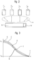
- FIG. 1 shows a schematic illustration of a multimobile elevator installation.
- Several vertically and horizontally self-propelled elevator cars C1..CN operate in an elevator system with, for example, four shafts 1 and the floors E1..EN.
- Each cabin C1..CN is driven by its own independent drive 1, for example by a frequency-controlled drive.
- the design can take place, for example, in the form of the friction wheel drive described in EP 556 595.
- each shaft 1 several cabins C1..CN can move up or down independently.
- the shafts 1 are each connected to one another at their upper and lower ends by a connecting passage 3. In this way, the cabins C1..CN can change their direction of travel by changing the shaft. The direction of travel can also be changed if there is only one cabin C1..CN in shaft 1.
- cabins C1 and C2 In the event of an emergency stop or when the safety gear intervenes, cabins C1 and C2, for example, require distances d1 and d2 as braking distances. A collision between the two cabins C1, C2 will occur if the distance d2-d1 is at the beginning of the braking phase.
- FIG. 2 shows a schematic representation of the elevator cars C1..CN with a safety module 10.
- the positions and speeds of each car C1 .. must be given to the safety module 10 at all times. CN to be known in the multimobile elevator group.
- this safety module 10 must be able to instantly decide the necessary braking behavior (characteristic of the deceleration curve, type of braking) for each cabin C1..CN.
- a communication system 11 ensures the transmission of information between the elevator cars C1..CN and the safety module 10.
- the safety device further includes a decision module 12 within the safety module 10, which is responsible for determining the stop commands.
- the decision module 12 continuously receives the positions, speeds and stopping options from all cabins C1..CN.
- the cabins C1..CN also send a stop request, which the decision module 12 processes and grants the cabin C1..CN permission to stop.
- the normal stop is regulated via the torque.
- a drum brake is used as the holding brake, for example.
- the safety gear arranged directly on the cabin can be designed, for example, as a roller safety gear. The decision and the type and also the location of the stopping is transmitted to the cabin by the decision module 12.
- the safety module 10 can also allow the cabins C1..CN in the same shaft 1 to have different directions of travel without causing collisions. This operation significantly increases the efficiency of the elevator group.
- a continuous data flow with the positions, speeds and destinations of the cabins C1..CN would require an infinite communication channel.
- a dynamic elevator model is integrated into the safety module 10. This model allows a very fast transmission of driving data (positions, speeds and destinations) and enables the decision module 12 to immediately determine and transmit the stopping commands to the cabins C1..CN.
- the target floor allocation is restricted in such a way that unnecessary stops and cars C1..CN blocked between floors E1..EN are avoided.
- FIG. 3 shows a deceleration curve D for elevator cars C1..CN.
- a cabin C1 drives through the shaft 1 at the nominal speed v n .
- the drive control follows the predetermined deceleration curve D, within a certain tolerance band Z, from the beginning of the deceleration at nominal speed v n at point A to the standstill v s of cabin C1 on the desired floor E1..EN at point F of the deceleration curve D. If the cabin C1 starts from a point B closer to the point F, it cannot be accelerated to the nominal speed v n , since otherwise the cabin C1 can no longer be brought to a standstill by means of deceleration values that are reasonable for the passengers. When the point C is reached, the drive control thus follows the deceleration curve D to a standstill v s at point F.
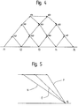
- FIG. 4 shows a dynamic model of the elevator travel curves for a building with five floors f1-f5.
- the driving curves for all possible floor distances, accelerations and decelerations are shown in the dynamic model.
- Selectors s i, j are the points of intersection between the acceleration curves from the starting floors i and the deceleration curves to the target floors j.
- the point f k is the stopping position on floor k.
- the information from all selectors s and stopping positions f and the transition time between these points form the dynamic model of an elevator system.
- Knowing the position of a relevant point of a cabin C1..CN in the network is equivalent to knowing the current positions and speeds. This allows the determination of the future positions and the stopping options of the cabins C1..CN. Therefore, a cabin C1..CN only has to indicate the position of a certain brand in the network in order to be able to transmit all the information required by the decision module 12.
- Such a message can take the following form, for example: ! 365.4 C1 s3.4
- This message announces that cabin C1 will reach selector s3.4 at time 365.4.
- the exclamation point! declares the message as information.
- the type of coding of the message can be freely selected and adapted to the communication system 11.
- the stopping commands are sent quickly and easily by the decision module 12. As the most important component, the command must contain the stopping position f k in the network, which the cabin C1..CN must reach.
- a stop command can take the following form, for example: !! 370.1 C1 f5
- This stop command instructs car C1 to reach floor f5.
- the double exclamation mark ! indicates that it is a stop command.
- the time specification 370.1 is optional. It corresponds to the maximum arrival time on floor f5. This implicitly defines the braking behavior (normal stop N, emergency stop E and safety gear P).
- stop commands There are other ways to formulate the stop commands. For example, it can be specified which of the braking behavior shown in FIG. 5 must be followed.
- the additional information [E] describes the braking behavior, in this case an emergency stop E, in order to be able to stop cabin C1 on floor f5.
- the stop commands are set implicitly.
- the decision module 12 can arrange a stop for a car C1..CN long before arriving at a selector f k. Therefore, the decision module 12 is free from any real-time problems, such as the commands for the brakes, etc.
- Each cabin C1..CN is responsible for monitoring its position and speed. Likewise, the cabins C1..CN are themselves responsible for initiating the braking phase or for deceleration control until the final stop, the stopping commands sent by the decision module 12 being followed.
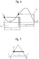
- FIG. 6 and 7 show schematic representations of the car states for the decision module 12.
- the decision module 12 must know the dimensions of the cars C1..CN, in particular their heights h, for monitoring the elevator installation.
- the decision module 12 takes the car height h into account as the length of the bar shown in FIG. Marks T represent the states of the cabins C1..CN in the network.
- a configuration as in FIG. 6 would occur between cabin C2 approaching floor f4 and cabin C1 when floor f4 leaves due to the overlap (hatched area) of the two cabins C1, C2 cause a collision.
- Such system states can be predicted and effectively prevented by the decision module 12.
- a stop module 21 sends the request to a receiver unit 22.
- a position module 25 the current driving data, in particular the car position and speed, are determined on the basis of shaft information 26 and the information supplied by a real-time clock 27. Position and speed are supplemented in a processing unit 28 with the dynamic model from module M1 and sent to an information unit 29.
- the data from the receiver unit 22 (stop request), the information unit 29 (position and speed) and a further dynamic model from a module M2 are processed and the braking behavior is determined.
- the braking behavior is transferred from the decision module 12 to a command generator 30, which generates the stop command.
- This stop command is transmitted to a brake module 31 of the cabin C1..CN, which is responsible for forwarding the command or initiating the braking phase.
- each cabin C1..CN can determine its braking behavior alone.
- Every cabin C1..CN has the possibility to control its stopping process itself.
- each cabin C1..CN can monitor other cabins, for example the following, and trigger an emergency stop if the monitored cabin C1..CN malfunctions.
- the distances between the cabs C1..CN can be kept as small as possible or as large as necessary with the help of the dynamic model to ensure optimal efficiency of elevator operation.
- sensors can also be used instead of the dynamic model.
- Sensors for example infrared sensors, are arranged at the top and bottom of each cabin C1..CN, which measure the distances to the cabins C1..CN located above and below in shaft 1.
- a shaft information system can be used to determine the positions of the cabins C1..CN, for example in the form of measuring strips arranged in the shafts 1, which are scanned by light barriers attached to the cabins C1..CN. In this way, the speed and position of each cabin C1..CN can be determined.
- These driving data are also transferred to safety modules 10 and the braking behavior of the cabins C1..CN is then determined.
- each safety device can also be used for multimobile elevator groups other than self-driving, for example an elevator group in which several cabs C1..CN run on ropes in the same shaft 1. Counterweights are arranged on the rope ends as compensation elements.
- each cabin C1..CN has its own independent drive, which is located in a machine room above or is attached below the shafts 1 or on the counterweight.
- the arrangement of the security modules 10 does not necessarily have to be on the cabins C1..CN; they can also be accommodated in the machine room or on floors E1..EN.
Abstract
Description
Die Erfindung betrifft eine Sicherheitseinrichtung für eine Multimobil-Aufzugsgruppe, die Kollisionen zwischen mehreren, in einem Schacht verkehrenden Aufzügen verhindert.The invention relates to a safety device for a multimobile elevator group, which prevents collisions between several elevators operating in a shaft.
Aus der EP 595 122 ist eine Aufzugsanlage mit mehreren Schächten bekanntgeworden, bei der mehrere vertikal und horizontal selbstfahrende Personentransporteinrichtungen im gleichen Schacht verkehren können. Jede Kabine kann horizontal von einem Schacht zu einem anderen Schacht fahren und ist mit einen eigenen Antrieb, beispielsweise mit einem Reibradantrieb versehen, dessen Reib- und Führungsräder in den Schachtecken abrollen. Jede Kabine besitzt ferner eine autonome Steuerung für die Verwaltung der Kabinen- bzw. Zielrufe, zu welchem Zweck die Distanz zu einer eventuell oberhalb oder unterhalb sich befindlichen Kabine gemessen wird. Zudem ist als Sicherheit gegen Übergeschwindigkeit oder bei Absturz am Hubwagen der Kabine eine gängige Fangvorrichtung vorgesehen.From EP 595 122 an elevator system with several shafts has become known, in which several vertically and horizontally self-propelled passenger transport devices can run in the same shaft. Each cabin can travel horizontally from one shaft to another and is provided with its own drive, for example with a friction wheel drive, the friction and guide wheels of which roll in the corners of the shaft. Each cabin also has an autonomous control for the management of the cabin or destination calls, for which purpose the distance to a cabin that may be above or below is measured. In addition, a common safety gear is provided as security against overspeed or in the event of a crash on the lift truck in the cabin.
Bei der vorstehend beschriebenen Einrichtung werden nur Sicherheitseinrichtungen für Übergeschwindigkeit oder Fehlbetrieb einer Kabine vorgesehen. Bei einem Nothalt oder auch bei einem normalen Stockwerkhalt einer Kabine kann nicht gewährleistet werden, ob ober- oder unterhalb im gleichen Schacht befindliche weitere Kabinen noch rechtzeitig anhalten können, um einen Zusammenstoss zu vermeiden.In the device described above, only safety devices for overspeed or malfunction of a cabin are provided. In the event of an emergency stop or a normal floor stop in a cabin, it cannot be guaranteed whether further cabins located above or below in the same shaft can still stop in time to avoid a collision.
Der Erfindung liegt die Aufgabe zugrunde, eine Sicherheitseinrichtung für eine Multimobil-Aufzugsgruppe der eingangs genannten Art vorzuschlagen, welche Kollisionen zwischen im gleichen Schacht befindlichen Kabinen verhindert.The invention has for its object to propose a safety device for a multimobile elevator group of the type mentioned, which Collisions between cabins in the same shaft prevented.
Diese Aufgabe wird durch die im Patentanspruch 1 gekennzeichnete Erfindung gelöst.This object is achieved by the invention characterized in
Die durch die Erfindung erreichten Vorteile sind im wesentlichen darin zu sehen, dass durch eine optimale Anpassung der Abstände zwischen den Kabinen mit Hilfe der Sicherheitseinrichtung die Leistungsfähigkeit der Multimobil-Aufzugsgruppe voll ausgenützt werden kann und dass das Sicherheitsmodul redundant ausgeführt ist, so dass sich die Aufzugsanlage nicht nur auf ein einziges Sicherheitsmodul verlassen muss.The advantages achieved by the invention can be seen essentially in the fact that by optimally adapting the distances between the cabins with the aid of the safety device, the performance of the multimobile elevator group can be fully utilized and that the safety module is designed redundantly, so that the elevator system can be used does not have to rely on a single security module.
Durch die in den Unteransprüchen aufgeführten Massnahmen sind vorteilhafte Weiterbildungen und Verbesserungen der im Anspruch 1 angegebenen Sicherheitseinrichtung für eine Multimobil-Aufzugsgruppe. Besonders eignet sich die Sicherheitseinrichtung für selbstfahrende Kabinen. Desweitern können durch die Anordnung eines Sicherheitsmoduls an jeder Kabine, andere Kabinen, beispielsweise eine im selben Schacht folgende, überwachen und einen Nothalt auslösen, wenn bei der überwachten Kabine eine Fehlfunktion auftritt.The measures listed in the subclaims are advantageous developments and improvements of the safety device specified in
In der Zeichnung ist ein Ausführungsbeispiel der Erfindung dargestellt und im folgenden näher erläutert. Es zeigen:
- Fig.1
- eine schematische Darstellung einer Multimobil-Aufzugsanlage,
- Fig.2
- eine schematische Darstellung der Aufzugskabinen mit der Sicherheitseinrichtung,
- Fig.3
- eine Verzögerungskurve für Aufzugskabinen,
- Fig.4
- ein Modell der Aufzugsfahrkurven,
- Fig.5
- eine schematische Darstellung der möglichen Bremsverhalten und der Anhaltekommandos für eine Kabine,
- Fig.6, 7
- eine schematische Darstellung der Kabinenzustände für das Entscheidungsmodul, und
- Fig.8
- eine schematische Darstellung der Komponenten für die Sicherheitseinrichtung.
- Fig. 1
- 1 shows a schematic representation of a multimobile elevator installation,
- Fig. 2
- 1 shows a schematic representation of the elevator cars with the safety device,
- Fig. 3
- a deceleration curve for elevator cars,
- Fig. 4
- a model of the elevator driving curves,
- Fig. 5
- a schematic representation of the possible braking behavior and the stopping commands for a cabin,
- Fig. 6, 7
- is a schematic representation of the cabin conditions for the decision module, and
- Fig. 8
- a schematic representation of the components for the safety device.
Fig.1 zeigt eine schematische Darstellung einer Multimobil-Aufzugsanlage. Mehrere vertikal und horizontal selbstfahrende Aufzugskabinen C1..CN verkehren in einer Aufzugsanlage mit beispielsweise vier Schächten 1 und den Stockwerken E1..EN. Jede Kabine C1..CN ist von einem eigenen unabhängigen Antrieb 1, beispielsweise von einem frequenzgeregelten Antrieb angetrieben. Die Ausführung kann beispielsweise in Form des in der EP 556 595 beschriebenen Reibradantriebes erfolgen. In jedem Schacht 1 können sich mehrere Kabinen C1..CN selbständig auf- oder abwärts bewegen. Die Schächte 1 sind an ihren oberen und unteren Enden jeweils mit einem Verbindungsgang 3 miteinander verbunden. Auf diese Weise können die Kabinen C1..CN durch einen Schachtwechsel ihre Fahrtrichtung ändern. Eine Änderung der Fahrtrichtung kann ebenfalls erfolgen, wenn sich nur eine Kabine C1..CN in einem Schacht 1 befindet.1 shows a schematic illustration of a multimobile elevator installation. Several vertically and horizontally self-propelled elevator cars C1..CN operate in an elevator system with, for example, four
In konventionellen Aufzugsgruppen sind der Notstop und das Eingreifen der Fangvorrichtung die zwei Grundprinzipien im Falle von Übergeschwindigkeit oder fehlerhaftem Betrieb. In einer Multimobil-Aufzugsgruppe, wie in Fig.1 gezeigt, können mehrere Kabinen C1..CN gleichzeitig im selben Schacht 1 verkehren. In einer solchen Aufzugsgruppe muss eine Sicherheitseinrichtung gewährleisten, dass im Fall von Übergeschwindigkeit oder fehlerhaftem Betrieb Kollisionen zwischen den Kabinen C1..CN verhindert werden können.In conventional elevator groups, the emergency stop and the intervention of the safety gear are the two basic principles in the event of excessive speed or incorrect operation. In a multimobile elevator group, as shown in FIG. 1, several cabins C1..CN can run simultaneously in the
Bei einem Notstop oder beim Eingreifen der Fangvorrichtung benötigen beispielsweise die Kabinen C1 und C2 die Strecken d1 beziehungsweise d2 als Bremswege. Eine Kollision zwischen den beiden Kabinen C1, C2 wird auftreten, wenn bei Beginn der Bremsphase der Abstand d2-d1 beträgt.In the event of an emergency stop or when the safety gear intervenes, cabins C1 and C2, for example, require distances d1 and d2 as braking distances. A collision between the two cabins C1, C2 will occur if the distance d2-d1 is at the beginning of the braking phase.
Ebenso bestehen Möglichkeiten von Kollisionen beim normalen Betrieb der Aufzugsgruppe:
- Rufzuweisung zu einer Kabine; Wird ein Stockwerkruf beispielsweise der Kabine C1 zugewiesen, so muss diese auf dem gewünschten Stockwerk anhalten und den Ruf bedienen. Bei einer solchen Situation muss berücksichtigt werden, dass die nachfolgende Kabine C2 ohne den normalen Betrieb zu beeinträchtigen, keine Kollision verursacht. Je nach Abstand zwischen den beiden Kabinen und der Dauer des Stops der Kabine C1 kann eine Verringerung der Geschwindigkeit der Kabine C2 genügen oder aber sie muss ebenfalls, beispielsweise auf einem höhergelegenen Stockwerk, anhalten.
- Horizontaltransfer von Kabinen C1..CN; Bei der Horizontalfahrt von Kabinen in den
Verbindungsgängen 3 müssen Kollisionen mit in denSchächten 1 vertikalfahrenden Kabinen vermieden werden.
- Call allocation to a cabin; If, for example, a floor call is assigned to car C1, it must stop on the desired floor and serve the call. In such a situation, it must be taken into account that the subsequent cabin C2 does not cause a collision without affecting normal operation. Depending on the distance between the two cars and the duration of the stop of car C1, a reduction in the speed of car C2 may be sufficient or else it must also stop, for example on a higher floor.
- Horizontal transfer of cabins C1..CN; When driving cabins horizontally in connecting
passages 3, collisions with cabins traveling vertically inshafts 1 must be avoided.
Um die oben beschriebenen Möglichkeiten von Kollisionen verhindern zu können, müssen die Betriebszustände aller in der Aufzugsgruppe verkehrender Kabinen C1..CN bekannt sein. Die Anhaltestrategie spielt dabei bei Multimobil-Aufzugsgruppen eine wesentliche Rolle. Die entscheidenden Aspekte sind die Sicherheit und die Leistungsfähigkeit der Aufzugsanlage. Ein zu grosser Sicherheitsabstand zwischen den Kabinen C1..CN verringert die Leistungsfähigkeit und somit die Vorteile einer Multimobil-Aufzugsanlage gegenüber einer konventionellen Aufzugsanlage. Zudem können mit einem grossen Abstand alleine Kollisionen nicht verhindert werden.In order to be able to prevent the possibilities of collisions described above, the operating states of all cars C1..CN operating in the elevator group must be known. The stopping strategy plays an important role in multi-mobile elevator groups. The crucial ones Aspects are the safety and performance of the elevator system. Too large a safety distance between the cabs C1..CN reduces the performance and thus the advantages of a multi-mobile elevator system compared to a conventional elevator system. In addition, collisions cannot be prevented with a large distance alone.
Fig.2 zeigt eine schematische Darstellung der Aufzugskabinen C1..CN mit einem Sicherheitsmodul 10. Um bei einem Anhaltebefehl für eine Kabine C1..CN keine Kollision zu verursachen, muss dem Sicherheitsmodul 10 zu jeder Zeit die Positionen und Geschwindigkeiten jeder Kabine C1..CN in der Multimobil-Aufzugsgruppe bekannt sein. Dieses Sicherheitsmodul 10 muss anhand dieser Fahrdaten für jede Kabine C1..CN augenblicklich das notwendige Bremsverhalten (Charakteristik der Verzögerungskurve, Art der Bremsung) entscheiden können. Ein Kommunikationssystem 11 sichert die Informationsübermittlung zwischen den Aufzugskabinen C1..CN und dem Sicherheitsmodul 10. Die Sicherheitseinrichtung beinhaltet weiter innerhalb des Sicherheitsmoduls 10 ein Entscheidungsmodul 12, welches für die Bestimmung der Anhaltebefehle verantwortlich ist. Das Entscheidungsmodul 12 empfängt laufend die Positionen, Geschwindigkeiten und Anhaltemöglichkeiten von allen Kabinen C1..CN. Die Kabinen C1..CN senden zudem eine Anhalteanfrage, die das Entscheidungsmodul 12 verarbeitet und der Kabine C1..CN die Anhalteerlaubnis erteilt.2 shows a schematic representation of the elevator cars C1..CN with a
Das Entscheidungsmodul 12 kann zu jeder Zeit entscheiden, eine Kabine abzubremsen oder zu stoppen. Es entscheidet auch ob eine Kabine C1..CN auf eine Anhalteanfrage hin anhalten darf oder nicht. Weiter bestimmt das Entscheidungsmodul 12 die Art des Anhaltens:
- Normaler Halt,
- Nothalt oder
- Auslösung der Fangvorrichtung.
- Normal stop,
- Emergency stop or
- Triggering the safety gear.
Der normale Halt wird beispielsweise bei einem frequenzgeregelten Antrieb über das Drehmoment geregelt. Bei einem Nothalt und zur Sicherung der Kabine C1..CN bei einem Halt auf einem Stockwerk E1..EN wird als Haltebremse zum Beispiel eine Trommelbremse verwendet. Die direkt an der Kabine angeordnete Fangvorrichtung kann beispielsweise als Rollenfangvorrichtung ausgeführt sein. Die Entscheidung und die Art und auch der Ort des Anhaltens wird der Kabine vom Entscheidungsmodul 12 übermittelt.For example, in the case of a frequency-controlled drive, the normal stop is regulated via the torque. In the event of an emergency stop and to secure the cabin C1..CN when stopping on a floor E1..EN, a drum brake is used as the holding brake, for example. The safety gear arranged directly on the cabin can be designed, for example, as a roller safety gear. The decision and the type and also the location of the stopping is transmitted to the cabin by the
Aufgrund der aktuellen Fahrdaten kann das Sicherheitsmodul 10 den Kabinen C1..CN im gleichen Schacht 1 auch unterschiedliche Fahrtrichtungen erlauben ohne Kollisionen zu verursachen. Dieser Fahrbetrieb erhöht wesentlich die Effizienz der Aufzugsgruppe.Based on the current driving data, the
Ein dauernder Datenfluss mit den Positionen, Geschwindigkeiten und Zielen der Kabinen C1..CN würde einen infiniten Kommunikationskanal benötigen. Aus diesem Grund wird in das Sicherheitsmodul 10 ein dynamisches Aufzugsmodell integriert. Dieses Modell erlaubt eine sehr schnelle Übertragung von Fahrdaten (Positionen, Geschwindigkeiten und Fahrzielen) und ermöglicht dem Entscheidungsmodul 12 eine unverzügliche Bestimmung und Übermittlung der Anhaltekommandos an die Kabinen C1..CN. Die Zielstockwerkzuteilung wird so eingeschränkt, dass unnötige Stops und zwischen den Stockwerken E1..EN blockierte Kabinen C1..CN vermieden werden.A continuous data flow with the positions, speeds and destinations of the cabins C1..CN would require an infinite communication channel. For this reason, a dynamic elevator model is integrated into the
Fig.3 zeigt eine Verzögerungskurve D für Aufzugskabinen C1..CN. Eine Kabine C1 durchfährt den Schacht 1 mit der Nenngeschwindigkeit vn. Um auf einem bestimmten Stockwerk E1..EN anhalten zu können, folgt die Antriebssteuerung der vorgegebenen Verzögerungskurve D, innerhalb von einem bestimmten Toleranzband Z, vom Beginn der Verzögerung mit Nenngeschwindigkeit vn beim Punkt A bis zum Stillstand vs der Kabine C1 auf dem gewünschten Stockwerk E1..EN beim Punkt F der Verzögerungskurve D. Startet die Kabine C1 von einem dem Punkt F nähergelegenen Punkt B, kann nicht bis auf die Nenngeschwindigkeit vn beschleunigt werden, da sonst die Kabine C1 nicht mehr mittels den Passagieren zumutbaren Verzögerungswerten zum Stillstand gebracht werden kann. Somit folgt die Antriebssteuerung beim Erreichen von Punkt C der Verzögerungskurve D bis zum Stillstand vs beim Punkt F.3 shows a deceleration curve D for elevator cars C1..CN. A cabin C1 drives through the
Fig.4 zeigt ein dynamisches Modell der Aufzugsfahrkurven für ein Gebäude mit fünf Stockwerken f1-f5. Gemäss der in Fig.3 gezeigten Verzögerungskurve D werden die Fahrkurven für alle möglichen Stockwerksdistanzen, Beschleunigungen und Verzögerungen im dynamischen Modell dargestellt. Selektoren s i,j sind die Schnittpunkte zwischen den Beschleunigungskurven von den Startstockwerken i und den Verzögerungskurven zu den Zielstockwerken j. Der Punkt f k ist die Halteposition auf Stockwerk k. Die Informationen von allen Selektoren s und Haltepositionen f und die Übergangszeit zwischen diesen Punkten bilden das dynamische Modell einer Aufzugsanlage.4 shows a dynamic model of the elevator travel curves for a building with five floors f1-f5. According to the deceleration curve D shown in FIG. 3, the driving curves for all possible floor distances, accelerations and decelerations are shown in the dynamic model. Selectors s i, j are the points of intersection between the acceleration curves from the starting floors i and the deceleration curves to the target floors j. The point f k is the stopping position on floor k. The information from all selectors s and stopping positions f and the transition time between these points form the dynamic model of an elevator system.
Die Kenntnis der Position eines relevanten Punktes einer Kabine C1..CN im Netzwerk ist gleichbedeutend mit dem Wissen der momentanen Positionen und Geschwindigkeiten. Dies erlaubt die Bestimmung der zukünftigen Positionen und die Anhaltemöglichkeiten der Kabinen C1..CN. Daher muss eine Kabine C1..CN nur die Position einer bestimmten Marke im Netzwerk anzuzeigen, um alle vom Entscheidungsmodul 12 verlangten Informationen übertragen zu können.Knowing the position of a relevant point of a cabin C1..CN in the network is equivalent to knowing the current positions and speeds. This allows the determination of the future positions and the stopping options of the cabins C1..CN. Therefore, a cabin C1..CN only has to indicate the position of a certain brand in the network in order to be able to transmit all the information required by the
Eine solche Nachricht kann beispielsweise in folgender Form erfolgen:
! 365.4 C1 s3,4Such a message can take the following form, for example:
! 365.4 C1 s3.4
Diese Nachricht gibt bekannt, dass Kabine C1 zur Zeit 365.4 den Selektor s3,4 erreichen wird. Das Ausrufezeichen ! deklariert die Nachricht als Information. Die Art der Codierung der Nachricht kann frei gewählt und an das Kommunikationssystem 11 angepasst werden.This message announces that cabin C1 will reach selector s3.4 at time 365.4. The exclamation point! declares the message as information. The type of coding of the message can be freely selected and adapted to the
Fig.5 zeigt eine schematische Darstellung der möglichen Bremsverhalten und der Anhaltekommandos einer Kabine. Das einfache und schnelle Senden der Anhaltekommandos erfolgt durch das Entscheidungsmodul 12. Als wichtigste Komponente muss das Kommando die Halteposition f k im Netzwerk, die die Kabine C1..CN erreichen muss, enthalten.5 shows a schematic representation of the possible braking behavior and the stopping commands of a cabin. The stopping commands are sent quickly and easily by the
Ein Anhaltebefehl kann beispielsweise in folgender Form erfolgen:
!! 370.1 C1 f5A stop command can take the following form, for example:
!! 370.1 C1 f5
Dieser Anhaltebefehl weist die Kabine C1 an, das Stockwerk f5 zu erreichen. Das doppelte Ausrufezeichen !! zeigt an, dass es sich um einen Anhaltebefehl handelt. Die Zeitangabe 370.1 ist optional. Sie entspricht der maximalen Ankunftszeit auf Stockwerk f5. Dadurch wird implizit das Bremsverhalten festgelegt (Normaler Stop N, Nothalt E und Fangvorrichtung P).This stop command instructs car C1 to reach floor f5. The double exclamation mark !! indicates that it is a stop command. The time specification 370.1 is optional. It corresponds to the maximum arrival time on floor f5. This implicitly defines the braking behavior (normal stop N, emergency stop E and safety gear P).
Es bestehen auch andere Möglichkeiten die Anhaltekommandos zu formulieren. Beispielsweise kann angegeben werden, welchem der in Figur 5 gezeigten Bremsverhalten gefolgt werden muss.There are other ways to formulate the stop commands. For example, it can be specified which of the braking behavior shown in FIG. 5 must be followed.
!! 370.1 C1 f5 [E]!! 370.1 C1 f5 [E]
Die zusätzliche Information [E] beschreibt das Bremsverhalten, in diesem Fall ein Nothalt E, um Kabine C1 auf Stockwerk f5 anhalten zu können.The additional information [E] describes the braking behavior, in this case an emergency stop E, in order to be able to stop cabin C1 on floor f5.
Die Anhaltekommandos sind implizit festgelegt. Das Entscheidungsmodul 12 kann einen Stop für eine Kabine C1..CN lange vor der Ankunft bei einem Selektor f k anordnen. Daher ist das Entscheidungsmodul 12 von jeglichen Echtzeitproblemen, wie beispielsweise die Befehle für die Bremsen usw., losgelöst. Jede Kabine C1..CN ist verantwortlich für die Überwachung seiner Position und Geschwindigkeit. Ebenso sind die Kabinen C1..CN selbst verantwortlich für die Einleitung der Bremsphase bzw. für die verzögerungskontrolle bis zum endgültigen Stop, wobei den vom Entscheidungsmodul 12 gesendeten Anhaltekommandos Folge geleistet wird.The stop commands are set implicitly. The
Fig.6 und 7 zeigen schematische Darstellungen der Kabinenzustände für das Entscheidungsmodul 12. Das Entscheidungsmodul 12 muss für die Überwachung der Aufzugsanlage die Dimensionen der Kabinen C1..CN, insbesondere deren Höhen h, kennen. Die Kabinenhöhe h wird vom Entscheidungsmodul 12 als Länge des in Fig.7 gezeigten Balkens berücksichtigt. Marken T stellen die Zustände der Kabinen C1..CN im Netzwerk dar. Eine Konfiguration wie in Fig.6 würde zwischen Kabine C2 in Annäherung auf Stockwerk f4 und Kabine C1 bei der Wegfahrt von Stockwerk f4 aufgrund der Überlappung (schraffierter Bereich) der beiden Kabinen C1, C2 eine Kollision verursachen. Solche Systemzustände können vom Entscheidungsmodul 12 vorhergesehen und wirksam verhindert werden.6 and 7 show schematic representations of the car states for the
Fig.8 zeigt eine schematische Darstellung der Komponenten für die gesamte Sicherheitseinrichtung. Alle Kabinen C1..CN teilen miteinander das in Fig.4 gezeigte dynamische Modell, bzw. jede Kabine C1..CN implementiert das dynamische Modell in ein Modul M1. Ebenso besitzt jede Kabine C1..CN ein Sicherheitsmodul 10. Durch die redundante Ausführung des Sicherheitsmoduls 10 wird die Sicherheit wesentlich erhöht, da sich die Aufzugsanlage nicht nur auf ein einziges Sicherheitsmodul 10 verlassen muss. Auf Anfrage der Aufzugssteuerung 20 sendet ein Anhaltemodul 21 die Anfrage an eine Empfängereinheit 22. In einem Positionsmodul 25 werden die aktuellen Fahrdaten, insbesondere die Kabinenposition und Geschwindigkeit, aufgrund von Schachtinformationen 26 und der von einer Echtzeituhr 27 gelieferten Informationen, bestimmt. Position und Geschwindigkeit werden in einer Verarbeitungseinheit 28 mit dem dynamischen Modell aus dem Modul M1 ergänzt und an eine Informationseinheit 29 gesendet. Im Entscheidungsmodul 12 werden die Daten aus der Empfängereinheit 22 (Anhalteanfrage), der Informationseinheit 29 (Position und Geschwindigkeit) und einem weiteren dynamischen Modell aus einem Modul M2 verarbeitet und das Bremsverhalten festgelegt. Vom Entscheidungsmodul 12 wird das Bremsverhalten einem Kommandogenerator 30 übergeben, welcher das Anhaltekommando erzeugt. Dieses Anhaltekommando wird einem Bremsmodul 31 der Kabine C1..CN übermittelt, welches für die Weiterleitung des Kommandos bzw. die Einleitung der Bremsphase verantwortlich ist.8 shows a schematic representation of the components for the entire safety device. All cabins C1..CN share the dynamic model shown in FIG. 4, or each cabin C1..CN implements the dynamic model in a module M1. Each cabin C1..CN likewise has a
Über das Kommunikationssystem 11 werden die Fahrdaten aller Kabinen C1..CN übermittelt. Entsprechend dem eigenen Zustand und den von den anderen Kabinen empfangenen Fahrdaten kann jede Kabine C1..CN sein Bremsverhalten alleine festlegen.The driving data of all cabins C1..CN are transmitted via the
Daher muss sich die Sicherheitseinrichtung nicht auf ein einziges Sicherheitsmodul 10 verlassen können. Jede Kabine C1..CN besitzt die Möglichkeit, seinen Anhalteprozess selber zu steuern. Zudem kann jede Kabine C1..CN andere Kabinen, beispielsweise die folgende, überwachen und einen Nothalt auslösen, wenn bei der überwachten Kabine C1..CN eine Fehlfunktion auftritt. Durch dieses System können desweitern mit Hilfe des dynamischen Modells die Abstände zwischen den Kabinen C1..CN so klein wie möglich, bzw. so gross wie nötig gehalten werden um eine optimale Effizienz des Aufzugbetriebs zu gewährleisten.The safety device therefore does not have to be able to rely on a
Als Variante zur Bestimmung der Fahrdaten können anstelle des dynamischen Modells auch Sensoren verwendet werden. An jeder Kabine C1..CN werden oben und unten Sensoren, beispielsweise Infrarotsensoren angeordnet, die die Distanzen zu oberhalb und unterhalb im Schacht 1 befindlichen Kabinen C1..CN messen. Zur Bestimmung der Positionen der Kabinen C1..CN kann ein Schachtinformationssystem dienen, zum Beispiel in Form von in den Schächten 1 angeordneten Messleisten, die von an den Kabinen C1..CN befestigten Lichtschranken abgetastet werden. Auf diese Weise kann die Geschwindigkeit und Position jeder Kabine C1..CN ermittelt werden. Diese Fahrdaten werden ebenfalls an Sicherheitsmodule 10 übergeben und anschliessend das Bremsverhalten der Kabinen C1..CN bestimmt.As a variant for determining the driving data, sensors can also be used instead of the dynamic model. Sensors, for example infrared sensors, are arranged at the top and bottom of each cabin C1..CN, which measure the distances to the cabins C1..CN located above and below in
Diese Sicherheitseinrichtungen sind auch auf andere als selbstfahrende Multimobil-Aufzugsgruppen anwendbar, beispielsweise auf eine Aufzugsgruppe bei der mehrere im gleichen Schacht 1 an Seilen geführte Kabinen C1..CN verkehren. Als Ausgleichsorgane werden an den Seilenden Gegengewichte angeordnet. Bei einer solchen Aufzugsgruppe besitzt jede Kabine C1..CN einen eigenen unabhängigen Antrieb, der in einem Maschinenraum oberhalb oder unterhalb der Schächte 1 oder am Gegengewicht angebracht ist.These safety devices can also be used for multimobile elevator groups other than self-driving, for example an elevator group in which several cabs C1..CN run on ropes in the
Die Anordnung der Sicherheitsmodule 10 muss nicht zwingend auf den Kabinen C1..CN erfolgen; sie können auch im Maschinenraum oder auf den Stockwerken E1..EN untergebracht werden.The arrangement of the
Claims (10)
dadurch gekennzeichnet,
dass mindestens ein Sicherheitsmodul (10) aus aktuellen Fahrdaten der Kabinen (C1..CN), insbesondere der Kabinenposition und Geschwindigkeit, aufgrund von Anhalteanfragen das notwendige Bremsverhalten der Kabinen (C1..CN) berechnet, so dass Kollisionen zwischen Kabinen (C1..CN) verhindert werden und dass vorzugsweise jede Kabine (C1..CN) mit einem eigenen Sicherheitsmodul (10) ausgerüstet ist.Safety device for a multimobile elevator group, in which several elevator cars (C1..CN) run simultaneously in at least one shaft (1) over several floors (E1..EN), each car (C1..CN) having its own independent drive (2) driven and provided with its own brake,
characterized,
that at least one safety module (10) calculates the necessary braking behavior of the cabins (C1..CN) from current driving data of the cabins (C1..CN), in particular the cabin position and speed, based on stop requests, so that collisions between cabins (C1 .. CN) can be prevented and that preferably each cabin (C1..CN) is equipped with its own safety module (10).
dadurch gekennzeichnet,
dass die Kabinen (C1..CN) als vertikal und vorzugsweise auch horizontal selbstfahrende Personentransporteinrichtungen ausgebildet sind.Safety device according to claim 1,
characterized,
that the cabins (C1..CN) are designed as vertical and preferably also horizontally self-propelled passenger transport devices.
dadurch gekennzeichnet,
dass die Kabinen (C1..CN) als seilgeführte Personentransporteinrichtungen ausgebildet sind.Safety device according to claim 1,
characterized,
that the cabins (C1..CN) are designed as cable-guided passenger transport devices.
dadurch gekennzeichnet,
dass bei Anbringung der Sicherheitsmodule (10) an den Kabinen (C1..CN) jedes Sicherheitsmodul (10) ausser bei der eigenen auch bei benachbarten Kabinen (C1..CN) Bremsvorgänge auslösen kann.Safety device according to one of claims 1 to 3,
characterized,
that when the safety modules (10) are attached to the cabins (C1..CN), each safety module (10) can trigger braking processes not only in its own but also in neighboring cabins (C1..CN).
dadurch gekennzeichnet,
dass das Bremsverhalten einem normalen Stockwerkhalt, einem Notstop oder einem Eingreifen der Fangvorrichtung entspricht.Safety device according to one of claims 1 to 4,
characterized,
that the braking behavior corresponds to a normal floor stop, an emergency stop or intervention by the safety gear.
dadurch gekennzeichnet,
dass zur Bestimmung der aktuellen Fahrdaten einer Kabine (C1..CN) ein dynamisches Modell einer Aufzugsfahrkurve beigezogen wird.Safety device according to one of claims 1 to 5,
characterized,
that a dynamic model of an elevator driving curve is used to determine the current driving data of a car (C1..CN).
dadurch gekennzeichnet,
dass die Bestimmung der aktuellen Fahrdaten mittels auf den Kabinen (C1..CN) angeordneten Sensoren und einem Schachtinformationssystem erfolgt.Safety device according to one of claims 1 to 5,
characterized,
that the current driving data is determined by means of sensors arranged on the cabins (C1..CN) and a shaft information system.
dadurch gekennzeichnet,
dass jedes Sicherheitsmodul (10) ein Entscheidungsmodul (12) enthält, welches aus den aktuellen Fahrdaten und Anhalteanfragen der Kabinen (C1..CN) das Bremsverhalten festlegt.Safety device according to one of claims 1 to 7,
characterized,
that each safety module (10) contains a decision module (12) which determines the braking behavior from the current driving data and stopping requests from the cabins (C1..CN).
dadurch gekennzeichnet,
dass jedes Entscheidungsmodul (12) das berechnete Bremsverhalten einem Kommandogenerator (30) weiterleitet, welcher das Anhaltekommando für die Kabinen (C1..CN) erzeugt.Safety device according to one of claims 1 to 8,
characterized,
that each decision module (12) forwards the calculated braking behavior to a command generator (30), which generates the stop command for the cabins (C1..CN).
dadurch gekennzeichnet,
dass jedes Entscheidungsmodul (12) einen Stockwerkhalt einer Kabine (C1..CN) unterbinden kann, um eine Kollision mit einer nachfolgenden Kabine (C1..CN) zu verhindern.Safety device according to one of claims 1 to 9,
characterized,
that each decision module (12) can prevent a floor of a car (C1..CN) to prevent a collision with a subsequent car (C1..CN).
Priority Applications (1)
| Application Number | Priority Date | Filing Date | Title |
|---|---|---|---|
| EP03013913A EP1371596B1 (en) | 1995-10-17 | 1996-10-04 | Safety device for a group of elevators |
Applications Claiming Priority (3)
| Application Number | Priority Date | Filing Date | Title |
|---|---|---|---|
| CH293595 | 1995-10-17 | ||
| CH2935/95 | 1995-10-17 | ||
| CH293595 | 1995-10-17 |
Related Child Applications (1)
| Application Number | Title | Priority Date | Filing Date |
|---|---|---|---|
| EP03013913A Division EP1371596B1 (en) | 1995-10-17 | 1996-10-04 | Safety device for a group of elevators |
Publications (2)
| Publication Number | Publication Date |
|---|---|
| EP0769469A1 true EP0769469A1 (en) | 1997-04-23 |
| EP0769469B1 EP0769469B1 (en) | 2003-12-17 |
Family
ID=4244942
Family Applications (2)
| Application Number | Title | Priority Date | Filing Date |
|---|---|---|---|
| EP03013913A Expired - Lifetime EP1371596B1 (en) | 1995-10-17 | 1996-10-04 | Safety device for a group of elevators |
| EP96115953A Expired - Lifetime EP0769469B1 (en) | 1995-10-17 | 1996-10-04 | Safety device for multi-mobile elevator groups |
Family Applications Before (1)
| Application Number | Title | Priority Date | Filing Date |
|---|---|---|---|
| EP03013913A Expired - Lifetime EP1371596B1 (en) | 1995-10-17 | 1996-10-04 | Safety device for a group of elevators |
Country Status (6)
| Country | Link |
|---|---|
| US (1) | US5877462A (en) |
| EP (2) | EP1371596B1 (en) |
| JP (1) | JP4008061B2 (en) |
| AT (2) | ATE256625T1 (en) |
| CA (1) | CA2187996C (en) |
| DE (2) | DE59611367D1 (en) |
Cited By (23)
| Publication number | Priority date | Publication date | Assignee | Title |
|---|---|---|---|---|
| WO2004043841A1 (en) * | 2002-11-09 | 2004-05-27 | Thyssenkrupp Elevator Ag | Safety device for an elevator system comprising a number of elevator cars inside a shaft |
| EP1894874A1 (en) * | 2006-08-31 | 2008-03-05 | Inventio Ag | Safety device for an elevator |
| EP1894875A1 (en) * | 2006-08-31 | 2008-03-05 | Inventio Ag | Safety device for a lift facility and a lift facility with such a safety device |
| EP1905717A1 (en) * | 2006-09-08 | 2008-04-02 | Inventio Ag | Method for operating a lift facility, a lift facility operated according to this method and a safety device for this lift facility |
| US7448471B2 (en) | 2005-03-05 | 2008-11-11 | Thyssenkrupp Elevator Ag | Elevator installation |
| WO2009038551A2 (en) * | 2007-09-18 | 2009-03-26 | Otis Elevator Company | Multiple car hoistway including car separation control |
| US7621376B2 (en) | 2004-07-15 | 2009-11-24 | Inventio Ag | Elevator installation and method for operating a vertical elevator shafts arranged adjacent to one another |
| WO2010072659A1 (en) * | 2008-12-26 | 2010-07-01 | Inventio Ag | Elevator control of an elevator installation |
| EP2347986A3 (en) * | 2001-09-28 | 2011-10-05 | Mitsubishi Denki K.K. | Elevator installation |
| RU2456225C2 (en) * | 2007-09-18 | 2012-07-20 | Отис Элевейтэ Кампэни | Method of retaining spacing in multicabin elevator well and elevator system |
| RU2464217C2 (en) * | 2006-12-21 | 2012-10-20 | Инвенцио Аг | Method to prevent collision of two elevator cabins and elevator |
| EP2522615A1 (en) * | 2003-03-18 | 2012-11-14 | Mitsubishi Denki Kabushiki Kaisha | Elevator apparatus and safety device for an elevator |
| EP2349901B1 (en) | 2008-11-28 | 2015-04-22 | Kone Corporation | Elevator system |
| EP3002242A1 (en) * | 2014-09-30 | 2016-04-06 | Inventio AG | Control method for an elevator system with individually driven cabins and closed track |
| WO2016058940A1 (en) * | 2014-10-16 | 2016-04-21 | Thyssenkrupp Elevator Ag | Method for operating a transport system and corresponding transport system |
| WO2016083114A1 (en) * | 2014-11-27 | 2016-06-02 | Thyssenkrupp Elevator Ag | Lift system having a plurality of cars and a decentralised safety system |
| CN106144852A (en) * | 2012-04-16 | 2016-11-23 | 三菱电机株式会社 | Many Lift car type elevator |
| CN107473032A (en) * | 2016-06-07 | 2017-12-15 | 奥的斯电梯公司 | Car Separation control in elevator with multiple compartments system |
| DE102017205354A1 (en) * | 2017-03-29 | 2018-10-04 | Thyssenkrupp Ag | Multi-cabin elevator system and method for operating a multi-car elevator system |
| DE102018202557A1 (en) * | 2018-02-20 | 2019-08-22 | Thyssenkrupp Ag | Collision prevention between cars |
| US10710841B2 (en) | 2014-11-27 | 2020-07-14 | Thyssenkrupp Elevator Ag | Method for operating an elevator system and elevator system designed for performing the method |
| CN111954634A (en) * | 2018-04-05 | 2020-11-17 | 蒂森克虏伯电梯创新与运营有限公司 | Method for operating an elevator installation |
| EP3233700B1 (en) * | 2014-12-17 | 2023-08-23 | Inventio Ag | Lift facility with a braking system |
Families Citing this family (89)
| Publication number | Priority date | Publication date | Assignee | Title |
|---|---|---|---|---|
| JP4326618B2 (en) * | 1999-02-03 | 2009-09-09 | 三菱電機株式会社 | Elevator group management device |
| JP4505901B2 (en) * | 1999-11-05 | 2010-07-21 | 三菱電機株式会社 | Elevator control device |
| JP2004002020A (en) * | 2002-05-27 | 2004-01-08 | Inventio Ag | Elevator facility provided with several self-travelling cars and at least three adjacently arranged elevator hoistways |
| JP4386842B2 (en) * | 2002-11-26 | 2009-12-16 | ティッセンクルップ エレバートル アーゲー | Elevator equipment control method and elevator equipment for executing the method |
| US6802395B1 (en) * | 2003-03-28 | 2004-10-12 | Kone Corporation | System for control and deceleration of elevator during emergency braking |
| US7198136B2 (en) * | 2003-09-11 | 2007-04-03 | Otis Elevator Company | Elevator device for a multi-sky-lobby system |
| EP1526104B1 (en) * | 2003-10-20 | 2006-06-07 | Inventio Ag | Safety system for a multi cabin elevator system |
| US7353914B2 (en) | 2003-10-20 | 2008-04-08 | Inventio Ag | Safety system for an elevator |
| JP2005170597A (en) * | 2003-12-11 | 2005-06-30 | Mitsubishi Electric Corp | Elevator control device and control method |
| JP4784509B2 (en) * | 2004-03-26 | 2011-10-05 | 三菱電機株式会社 | Elevator group management control device |
| US7392883B2 (en) * | 2004-03-30 | 2008-07-01 | Mitsubishi Denki Kabushiki Kaisha | Elevator group control system |
| JP4668186B2 (en) * | 2004-04-06 | 2011-04-13 | 三菱電機株式会社 | Elevator equipment |
| EP1765710A4 (en) | 2004-06-21 | 2011-09-21 | Otis Elevator Co | Elevator system including multiple cars in a hoistway |
| CN101665204B (en) * | 2004-06-21 | 2012-04-25 | 奥蒂斯电梯公司 | Elevator system containing multiple cabins in vertical shaft |
| TWI343357B (en) * | 2004-07-22 | 2011-06-11 | Inventio Ag | Elevator installation with individually movable elevator cars and method for operating such an elevator installation |
| DE102004037486B4 (en) * | 2004-07-27 | 2006-08-10 | ThyssenKrupp Aufzüge GmbH | Signal band and system for determining a state of motion of a moving body, and apparatus for speed limiting the moving body, in particular an elevator car, using the same |
| JP2006062821A (en) * | 2004-08-26 | 2006-03-09 | Ohbayashi Corp | Carrying mechanism |
| EP1783083B1 (en) * | 2004-08-26 | 2013-08-14 | Mitsubishi Denki Kabushiki Kaisha | Elevator group management controller |
| WO2006025103A1 (en) * | 2004-08-31 | 2006-03-09 | Mitsubishi Denki Kabushiki Kaisha | Controller of one-shaft multi-car system elevator |
| WO2006065241A2 (en) | 2004-12-16 | 2006-06-22 | Otis Elevator Company | Elevator system with multiple cars in a hoistway |
| WO2006071222A1 (en) | 2004-12-29 | 2006-07-06 | Otis Elevator Company | Compensation in an elevator system having multiple cars within a single hoistway |
| KR100946353B1 (en) | 2005-02-04 | 2010-03-08 | 오티스 엘리베이터 컴파니 | Calls assigned to one of two cars in a hoistway to minimize delay imposed on either car |
| EP1853506B1 (en) * | 2005-02-04 | 2011-11-02 | Otis Elevator Company | Announcements indicating one car is waiting for another car in the same hoistway |
| CN101119916B (en) * | 2005-02-17 | 2010-09-29 | 奥蒂斯电梯公司 | Collision prevention in hoistway with two elevator cars |
| CN100554120C (en) | 2005-02-17 | 2009-10-28 | 奥蒂斯电梯公司 | The method of elevator passenger is informed in the operation that car is gone to pit or top |
| DE112005003475B4 (en) | 2005-02-25 | 2019-04-18 | Otis Elevator Co. | Elevator car with an angled beam stranding arrangement |
| JP2006290575A (en) * | 2005-04-13 | 2006-10-26 | Otis Elevator Co | Elevator device |
| AU2006237317B8 (en) | 2005-04-19 | 2011-05-12 | Basf Plant Science Gmbh | Improved methods controlling gene expression |
| US7357226B2 (en) * | 2005-06-28 | 2008-04-15 | Masami Sakita | Elevator system with multiple cars in the same hoistway |
| US7841450B2 (en) * | 2005-08-19 | 2010-11-30 | Thyssenkrupp Elevator Capital Corporation | Twin elevator systems |
| US7842856B2 (en) | 2005-08-25 | 2010-11-30 | The Board Of Trustees Of The University Of Illinois | Herbicide resistance gene, compositions and methods |
| US7671254B2 (en) * | 2005-08-25 | 2010-03-02 | The Board Of Trustees Of The University Of Illinois | Herbicide resistance gene, compositions and methods |
| CA2620387C (en) | 2005-09-20 | 2018-09-18 | Basf Plant Science Gmbh | Methods for controlling gene expression using ta-sirna |
| JP4800723B2 (en) * | 2005-09-27 | 2011-10-26 | 株式会社日立製作所 | Elevator group management system and control method thereof |
| US8356697B2 (en) * | 2005-10-25 | 2013-01-22 | Otis Elevator Company | Elevator safety system and method |
| CN101460385B (en) * | 2006-06-07 | 2013-09-18 | 奥蒂斯电梯公司 | Method for controlling operation of multiple cars in a hoistway |
| EP2032489B1 (en) * | 2006-06-07 | 2018-12-05 | Otis Elevator Company | Multi-car elevator hoistway separation assurance |
| SG138530A1 (en) * | 2006-06-19 | 2008-01-28 | Inventio Ag | Lift installation and method of operating a lift installation |
| KR100784040B1 (en) | 2006-09-22 | 2007-12-10 | 오티스 엘리베이터 컴파니 | Elevator system including multiple cars in a hoistway |
| WO2008079147A1 (en) | 2006-12-22 | 2008-07-03 | Otis Elevator Company | Elevator system with multiple cars in a single hoistway |
| CA2674499A1 (en) | 2007-02-06 | 2008-08-14 | Basf Plant Science Gmbh | Use of alanine racemase genes to confer nematode resistance to plants |
| WO2008110522A1 (en) | 2007-03-15 | 2008-09-18 | Basf Plant Science Gmbh | Use of nematode chitinase genes to control plant parasitic nematodes |
| KR100898916B1 (en) * | 2007-04-02 | 2009-05-26 | 최성식 | System for intelligent elevator and control method thereof |
| WO2008120849A1 (en) * | 2007-04-02 | 2008-10-09 | Sungsik Choi | Elevator system and control method thereof |
| EP2022742B1 (en) * | 2007-08-07 | 2014-06-25 | ThyssenKrupp Elevator AG | Lift system |
| US8297409B2 (en) * | 2007-11-30 | 2012-10-30 | Otis Elevator Company | Coordination of multiple elevator cars in a hoistway |
| WO2009073025A1 (en) | 2007-12-05 | 2009-06-11 | Otis Elevator Company | Control strategy for operating two elevator cars in a single hoistway |
| US8371420B2 (en) * | 2007-12-17 | 2013-02-12 | Mitsubishi Electric Corporation | Elevator system for reducing collision shock |
| US8540057B2 (en) * | 2008-03-06 | 2013-09-24 | Inventio Ag | Generating elevator installation maintenance information |
| MX2011001356A (en) | 2008-08-27 | 2011-03-29 | Basf Plant Science Gmbh | Nematode-resistant transgenic plants. |
| BRPI0922513A2 (en) | 2008-12-11 | 2015-08-04 | Basf Plant Science Gmbh | Isolated expression vector, agrobacterium, method for transferring two or more genes into the cell nucleus, to prepare a nematode resistant transgenic plant, transgenic plant, and seed. |
| US20110240412A1 (en) * | 2008-12-17 | 2011-10-06 | Schienda Greg A | Elevator braking control |
| ES2424029T3 (en) * | 2008-12-23 | 2013-09-26 | Inventio Ag | Elevator installation |
| JP5064454B2 (en) * | 2009-08-12 | 2012-10-31 | 三菱電機株式会社 | Elevator equipment |
| US20120151629A1 (en) | 2009-08-25 | 2012-06-14 | Basf Plant Science Company Gmbh | Nematode-Resistant Transgenic Plants |
| US8602168B2 (en) * | 2010-02-10 | 2013-12-10 | Inventio Ag | Moving multiple cages between elevator shaft sides |
| JP5404907B2 (en) | 2010-03-01 | 2014-02-05 | 三菱電機株式会社 | Multi-car elevator control device |
| US8424651B2 (en) * | 2010-11-17 | 2013-04-23 | Mitsubishi Electric Research Laboratories, Inc. | Motion planning for elevator cars moving independently in one elevator shaft |
| WO2012066937A1 (en) * | 2010-11-17 | 2012-05-24 | Mitsubishi Electric Corporation | Method and system for controlling a motion of a first car and a second car in a multi-car elevator system |
| EP2465804A1 (en) | 2010-12-16 | 2012-06-20 | Inventio AG | Multi-cabin lift with brake status indicator |
| CA2822004A1 (en) | 2010-12-20 | 2012-06-28 | Basf Plant Science Company Gmbh | Nematode-resistant transgenic plants |
| EP2695838B1 (en) * | 2011-04-08 | 2016-09-28 | Mitsubishi Electric Corporation | Multi-car elevator and method for controlling same |
| WO2013050611A1 (en) | 2011-10-07 | 2013-04-11 | Basf Plant Science Company Gmbh | Method of producing plants having increased resistance to pathogens |
| WO2013050593A1 (en) | 2011-10-07 | 2013-04-11 | Basf Plant Science Company Gmbh | Method of producing plants having increased resistance to pathogens |
| WO2013050318A1 (en) | 2011-10-07 | 2013-04-11 | Basf Plant Science Company Gmbh | Method of producing plants having increased resistance to pathogens |
| WO2013053686A1 (en) | 2011-10-10 | 2013-04-18 | Basf Plant Science Company Gmbh | Method of producing plants having increased resistance to pathogens |
| WO2013053711A1 (en) | 2011-10-10 | 2013-04-18 | Basf Plant Science Company Gmbh | Method of producing plants having increased resistance to pathogens |
| EP2607282A1 (en) * | 2011-12-23 | 2013-06-26 | Inventio AG | Safety device for a lift with multiple cabins |
| CN104245557B (en) * | 2012-04-16 | 2016-10-19 | 三菱电机株式会社 | Many Lift car type elevator |
| EP2957535A1 (en) | 2012-04-26 | 2015-12-23 | Fritz KING | Articulated funiculator |
| US10124986B2 (en) * | 2013-07-10 | 2018-11-13 | Mitsubishi Electric Corporation | Elevator control device for maximizing a number of floors serviced |
| CN105939948B (en) * | 2013-12-05 | 2019-11-05 | 奥的斯电梯公司 | Destination distribution and varying ability in eleva-tor bank |
| US20170121147A1 (en) * | 2014-06-16 | 2017-05-04 | Otis Elevator Company | Destination dispatch overlay including car positioning monitoring system |
| FI125875B (en) * | 2014-08-22 | 2016-03-15 | Kone Corp | Method and arrangement for closing doors of an elevator |
| US9758347B2 (en) | 2014-12-02 | 2017-09-12 | ThyssenKrupp Elevator AG; ThyssenKrupp AG | Arrangement and method to move at least two elevator cars independently in at least one hoistway |
| DE102015102564A1 (en) * | 2015-02-23 | 2016-08-25 | Thyssenkrupp Ag | Elevator system with several shafts and several cabins and additional cabin receiving shaft |
| DE102015102563A1 (en) * | 2015-02-23 | 2016-08-25 | Thyssenkrupp Ag | Method for operating an elevator system with several shafts and several cabins |
| AU2016231585B2 (en) * | 2015-09-25 | 2018-08-09 | Otis Elevator Company | Elevator component separation assurance system and method of operation |
| US9650226B2 (en) * | 2015-09-28 | 2017-05-16 | Smart Lifts, Llc | System and method for controlling multiple elevator cabs in an elevator shaft |
| US10427908B2 (en) * | 2016-04-15 | 2019-10-01 | Otis Elevator Company | Emergency mode operation of elevator system having linear propulsion system |
| EP3257799B1 (en) * | 2016-06-17 | 2022-02-23 | KONE Corporation | Redundant safety circuit |
| US10494229B2 (en) * | 2017-01-30 | 2019-12-03 | Otis Elevator Company | System and method for resilient design and operation of elevator system |
| EP3357851B1 (en) | 2017-02-06 | 2023-08-02 | KONE Corporation | Mechanism for improving safety for an elevator system |
| DE102017205353A1 (en) | 2017-03-29 | 2018-10-04 | Thyssenkrupp Ag | Elevator installation with a plurality of elevator cars having an identification and method for operating such an elevator installation |
| US10501286B2 (en) | 2017-05-12 | 2019-12-10 | Otis Elevator Company | Simultaneous elevator car and counterweight safety actuation |
| CN110127484B (en) * | 2019-06-14 | 2023-11-14 | 嘉兴技师学院 | Elevator bridge box operation position monitoring and early warning system and method |
| JP7373433B2 (en) * | 2020-02-26 | 2023-11-02 | 株式会社日立製作所 | Elevator control system and elevator control method |
| US20220033217A1 (en) * | 2020-07-30 | 2022-02-03 | Otis Elevator Company | Multi-car elevator system with autonomous car movers configured for collision avoidance |
| JP7004055B1 (en) * | 2020-12-17 | 2022-01-21 | 三菱電機株式会社 | Elevator system |
Citations (5)
| Publication number | Priority date | Publication date | Assignee | Title |
|---|---|---|---|---|
| JPS6316383A (en) * | 1986-07-09 | 1988-01-23 | Fuji Electric Co Ltd | Shape recognizing method |
| GB2217046A (en) * | 1988-03-31 | 1989-10-18 | Toshiba Kk | Group control of elevators utilizing distributed control |
| WO1992018411A1 (en) * | 1991-04-12 | 1992-10-29 | Mitsubishi Denki Kabushiki Kaisha | Method of controlling a plurality of elevators moving in a common hoistway |
| JPH0551185A (en) * | 1991-08-27 | 1993-03-02 | Toshiba Corp | Self-traveling elevator control device |
| US5419414A (en) * | 1993-11-18 | 1995-05-30 | Sakita; Masami | Elevator system with multiple cars in the same hoistway |
Family Cites Families (3)
| Publication number | Priority date | Publication date | Assignee | Title |
|---|---|---|---|---|
| HU213428B (en) * | 1992-10-27 | 1997-06-30 | Inventio Ag | Self propelled device mainly for passanger carriing |
| JPH06316383A (en) * | 1993-05-07 | 1994-11-15 | Toshiba Corp | Self-traveling elevator |
| JPH07187525A (en) * | 1993-11-18 | 1995-07-25 | Masami Sakita | Elevator system with plural cars |
-
1996
- 1996-10-04 DE DE59611367T patent/DE59611367D1/en not_active Expired - Lifetime
- 1996-10-04 DE DE59610869T patent/DE59610869D1/en not_active Expired - Lifetime
- 1996-10-04 AT AT96115953T patent/ATE256625T1/en not_active IP Right Cessation
- 1996-10-04 EP EP03013913A patent/EP1371596B1/en not_active Expired - Lifetime
- 1996-10-04 AT AT03013913T patent/ATE333431T1/en not_active IP Right Cessation
- 1996-10-04 EP EP96115953A patent/EP0769469B1/en not_active Expired - Lifetime
- 1996-10-11 US US08/728,955 patent/US5877462A/en not_active Expired - Fee Related
- 1996-10-16 CA CA002187996A patent/CA2187996C/en not_active Expired - Fee Related
- 1996-10-17 JP JP27502196A patent/JP4008061B2/en not_active Expired - Fee Related
Patent Citations (5)
| Publication number | Priority date | Publication date | Assignee | Title |
|---|---|---|---|---|
| JPS6316383A (en) * | 1986-07-09 | 1988-01-23 | Fuji Electric Co Ltd | Shape recognizing method |
| GB2217046A (en) * | 1988-03-31 | 1989-10-18 | Toshiba Kk | Group control of elevators utilizing distributed control |
| WO1992018411A1 (en) * | 1991-04-12 | 1992-10-29 | Mitsubishi Denki Kabushiki Kaisha | Method of controlling a plurality of elevators moving in a common hoistway |
| JPH0551185A (en) * | 1991-08-27 | 1993-03-02 | Toshiba Corp | Self-traveling elevator control device |
| US5419414A (en) * | 1993-11-18 | 1995-05-30 | Sakita; Masami | Elevator system with multiple cars in the same hoistway |
Non-Patent Citations (2)
| Title |
|---|
| PATENT ABSTRACTS OF JAPAN vol. 0, no. 0 * |
| PATENT ABSTRACTS OF JAPAN vol. 17, no. 358 (M - 1440) 7 July 1993 (1993-07-07) * |
Cited By (40)
| Publication number | Priority date | Publication date | Assignee | Title |
|---|---|---|---|---|
| EP2347986A3 (en) * | 2001-09-28 | 2011-10-05 | Mitsubishi Denki K.K. | Elevator installation |
| WO2004043842A1 (en) * | 2002-11-09 | 2004-05-27 | Thyssenkrupp Elevator Ag | Safety system for elevator system, comprising several elevator cars in a cage |
| KR100714174B1 (en) * | 2002-11-09 | 2007-05-02 | 티센크루프 엘리베이터 에이지 | Safety system for elevator system, comprising several elevator cars in a cage |
| WO2004043841A1 (en) * | 2002-11-09 | 2004-05-27 | Thyssenkrupp Elevator Ag | Safety device for an elevator system comprising a number of elevator cars inside a shaft |
| US7353912B2 (en) | 2002-11-09 | 2008-04-08 | Thyssenkrupp Elevator Ag | Elevator system |
| EP2522615A1 (en) * | 2003-03-18 | 2012-11-14 | Mitsubishi Denki Kabushiki Kaisha | Elevator apparatus and safety device for an elevator |
| US7621376B2 (en) | 2004-07-15 | 2009-11-24 | Inventio Ag | Elevator installation and method for operating a vertical elevator shafts arranged adjacent to one another |
| US7448471B2 (en) | 2005-03-05 | 2008-11-11 | Thyssenkrupp Elevator Ag | Elevator installation |
| US7980362B2 (en) | 2006-08-31 | 2011-07-19 | Inventio Ag | Safety equipment for preventing an elevator car collision with an object |
| EP1894874A1 (en) * | 2006-08-31 | 2008-03-05 | Inventio Ag | Safety device for an elevator |
| EP1894875A1 (en) * | 2006-08-31 | 2008-03-05 | Inventio Ag | Safety device for a lift facility and a lift facility with such a safety device |
| EP1905717A1 (en) * | 2006-09-08 | 2008-04-02 | Inventio Ag | Method for operating a lift facility, a lift facility operated according to this method and a safety device for this lift facility |
| US7779967B2 (en) | 2006-09-08 | 2010-08-24 | Inventio Ag | Method of operating an elevator installation, an elevator installation operable by this method and safety equipment for this elevator installation |
| EP1935823B2 (en) † | 2006-12-21 | 2017-06-28 | Inventio AG | Method for preventing the collision of two lift cabins moving in one shaft and corresponding lift system |
| RU2464217C2 (en) * | 2006-12-21 | 2012-10-20 | Инвенцио Аг | Method to prevent collision of two elevator cabins and elevator |
| WO2009038551A3 (en) * | 2007-09-18 | 2009-05-14 | Otis Elevator Co | Multiple car hoistway including car separation control |
| CN101801790B (en) * | 2007-09-18 | 2012-07-18 | 奥蒂斯电梯公司 | Multiple car hoistway including car separation control |
| RU2456225C2 (en) * | 2007-09-18 | 2012-07-20 | Отис Элевейтэ Кампэни | Method of retaining spacing in multicabin elevator well and elevator system |
| WO2009038551A2 (en) * | 2007-09-18 | 2009-03-26 | Otis Elevator Company | Multiple car hoistway including car separation control |
| US8434599B2 (en) | 2007-09-18 | 2013-05-07 | Otis Elevator Company | Multiple car hoistway including car separation control |
| EP2349901B1 (en) | 2008-11-28 | 2015-04-22 | Kone Corporation | Elevator system |
| US8827043B2 (en) | 2008-12-26 | 2014-09-09 | Inventio Ag | Elevator control and method for independently movable cars in a common shaft |
| WO2010072659A1 (en) * | 2008-12-26 | 2010-07-01 | Inventio Ag | Elevator control of an elevator installation |
| CN106144852B (en) * | 2012-04-16 | 2018-09-25 | 三菱电机株式会社 | More Lift car type elevators |
| CN106144852A (en) * | 2012-04-16 | 2016-11-23 | 三菱电机株式会社 | Many Lift car type elevator |
| EP3002242A1 (en) * | 2014-09-30 | 2016-04-06 | Inventio AG | Control method for an elevator system with individually driven cabins and closed track |
| WO2016058940A1 (en) * | 2014-10-16 | 2016-04-21 | Thyssenkrupp Elevator Ag | Method for operating a transport system and corresponding transport system |
| US10703603B2 (en) | 2014-10-16 | 2020-07-07 | Thyssenkrupp Elevator Ag | Operating a cyclical transport system based on an equal cycle time |
| EP3599208A1 (en) * | 2014-11-27 | 2020-01-29 | thyssenkrupp AG | Lift system having a plurality of cars and a decentralised safety system |
| US10464782B2 (en) | 2014-11-27 | 2019-11-05 | Thyssenkrupp Ag | Lift system having a plurality of cars and a decentralised safety system |
| CN107000985B (en) * | 2014-11-27 | 2019-12-06 | 蒂森克虏伯电梯股份公司 | Elevator system comprising a plurality of elevator cars and a distributed safety system |
| CN107000985A (en) * | 2014-11-27 | 2017-08-01 | 蒂森克虏伯电梯股份公司 | Elevator device including multiple lift cars and distributed secure system |
| WO2016083114A1 (en) * | 2014-11-27 | 2016-06-02 | Thyssenkrupp Elevator Ag | Lift system having a plurality of cars and a decentralised safety system |
| US10710841B2 (en) | 2014-11-27 | 2020-07-14 | Thyssenkrupp Elevator Ag | Method for operating an elevator system and elevator system designed for performing the method |
| EP3233700B1 (en) * | 2014-12-17 | 2023-08-23 | Inventio Ag | Lift facility with a braking system |
| CN107473032A (en) * | 2016-06-07 | 2017-12-15 | 奥的斯电梯公司 | Car Separation control in elevator with multiple compartments system |
| CN107473032B (en) * | 2016-06-07 | 2021-04-23 | 奥的斯电梯公司 | Inter-car spacing control in multi-car elevator system |
| DE102017205354A1 (en) * | 2017-03-29 | 2018-10-04 | Thyssenkrupp Ag | Multi-cabin elevator system and method for operating a multi-car elevator system |
| DE102018202557A1 (en) * | 2018-02-20 | 2019-08-22 | Thyssenkrupp Ag | Collision prevention between cars |
| CN111954634A (en) * | 2018-04-05 | 2020-11-17 | 蒂森克虏伯电梯创新与运营有限公司 | Method for operating an elevator installation |
Also Published As
| Publication number | Publication date |
|---|---|
| CA2187996C (en) | 2005-08-02 |
| ATE333431T1 (en) | 2006-08-15 |
| US5877462A (en) | 1999-03-02 |
| EP1371596B1 (en) | 2006-07-19 |
| DE59610869D1 (en) | 2004-01-29 |
| CA2187996A1 (en) | 1997-04-18 |
| JPH09110316A (en) | 1997-04-28 |
| DE59611367D1 (en) | 2006-08-31 |
| EP1371596A1 (en) | 2003-12-17 |
| ATE256625T1 (en) | 2004-01-15 |
| EP0769469B1 (en) | 2003-12-17 |
| JP4008061B2 (en) | 2007-11-14 |
Similar Documents
| Publication | Publication Date | Title |
|---|---|---|
| EP0769469B1 (en) | Safety device for multi-mobile elevator groups | |
| EP2370334B1 (en) | Elevator control of an elevator installation | |
| EP3206982B1 (en) | Method for operating a transport system and corresponding transport system | |
| EP1401757B1 (en) | Method for preventing an inadmissibly high speed of the load receiving means of an elevator | |
| EP1619157B2 (en) | Elevator system with independently movable elevator cars and method for controlling its movement | |
| EP1418147B1 (en) | Controller for elevator with multi-deck car | |
| EP2229332B1 (en) | Operating method for an elevator having two elevator cabs and one counterweight | |
| EP2794449B1 (en) | Safety device for a lift with multiple cabins | |
| WO2018177829A1 (en) | Multi-cage lift installation and method for operating a multi-cage lift installation | |
| EP2367746A1 (en) | Elevator installation | |
| EP1693331A1 (en) | Elevator system with several shafts and with elevator cars that can be coupled and uncoupled from the selected drive system. | |
| EP1526103B1 (en) | Multiple deck elevator system for group elevators | |
| WO2019081316A1 (en) | Elevator system having shaft-changing units and method for operating an elevator system having shaft-changing units | |
| EP3227216B1 (en) | Elevator system | |
| WO2017005864A1 (en) | Method for operating a lift system, control system, and lift system | |
| EP3037375A1 (en) | Elevator installation with a holding and adjusting system for an elevator cabin assembly | |
| DE112017004022T5 (en) | LIFT SYSTEM | |
| DE102004048993B4 (en) | System and method for controlling rail-bound vehicles, in particular trains, by means of a control center, depending on the condition of the travel path, in particular the available coefficient of friction | |
| WO2018206413A1 (en) | Elevator system having two shafts | |
| WO2024061766A1 (en) | Method for operating a lift system | |
| WO2017167758A1 (en) | Elevator system |
Legal Events
| Date | Code | Title | Description |
|---|---|---|---|
| PUAI | Public reference made under article 153(3) epc to a published international application that has entered the european phase |
Free format text: ORIGINAL CODE: 0009012 |
|
| AK | Designated contracting states |
Kind code of ref document: A1 Designated state(s): AT CH DE FR GB LI |
|
| 17P | Request for examination filed |
Effective date: 19970919 |
|
| 17Q | First examination report despatched |
Effective date: 20010207 |
|
| GRAH | Despatch of communication of intention to grant a patent |
Free format text: ORIGINAL CODE: EPIDOS IGRA |
|
| GRAS | Grant fee paid |
Free format text: ORIGINAL CODE: EPIDOSNIGR3 |
|
| GRAA | (expected) grant |
Free format text: ORIGINAL CODE: 0009210 |
|
| AK | Designated contracting states |
Kind code of ref document: B1 Designated state(s): AT CH DE FR GB LI |
|
| REG | Reference to a national code |
Ref country code: GB Ref legal event code: FG4D Free format text: NOT ENGLISH |
|
| REG | Reference to a national code |
Ref country code: CH Ref legal event code: EP |
|
| REF | Corresponds to: |
Ref document number: 59610869 Country of ref document: DE Date of ref document: 20040129 Kind code of ref document: P |
|
| GBT | Gb: translation of ep patent filed (gb section 77(6)(a)/1977) |
Effective date: 20040118 |
|
| ET | Fr: translation filed | ||
| PLBE | No opposition filed within time limit |
Free format text: ORIGINAL CODE: 0009261 |
|
| STAA | Information on the status of an ep patent application or granted ep patent |
Free format text: STATUS: NO OPPOSITION FILED WITHIN TIME LIMIT |
|
| 26N | No opposition filed |
Effective date: 20040920 |
|
| PGFP | Annual fee paid to national office [announced via postgrant information from national office to epo] |
Ref country code: AT Payment date: 20081015 Year of fee payment: 13 |
|
| PGFP | Annual fee paid to national office [announced via postgrant information from national office to epo] |
Ref country code: CH Payment date: 20090116 Year of fee payment: 13 |
|
| REG | Reference to a national code |
Ref country code: CH Ref legal event code: PL |
|
| PG25 | Lapsed in a contracting state [announced via postgrant information from national office to epo] |
Ref country code: AT Free format text: LAPSE BECAUSE OF NON-PAYMENT OF DUE FEES Effective date: 20091004 |
|
| PG25 | Lapsed in a contracting state [announced via postgrant information from national office to epo] |
Ref country code: LI Free format text: LAPSE BECAUSE OF NON-PAYMENT OF DUE FEES Effective date: 20091031 Ref country code: CH Free format text: LAPSE BECAUSE OF NON-PAYMENT OF DUE FEES Effective date: 20091031 |
|
| PGFP | Annual fee paid to national office [announced via postgrant information from national office to epo] |
Ref country code: DE Payment date: 20101022 Year of fee payment: 15 |
|
| PGFP | Annual fee paid to national office [announced via postgrant information from national office to epo] |
Ref country code: GB Payment date: 20101021 Year of fee payment: 15 |
|
| PGFP | Annual fee paid to national office [announced via postgrant information from national office to epo] |
Ref country code: FR Payment date: 20111103 Year of fee payment: 16 |
|
| GBPC | Gb: european patent ceased through non-payment of renewal fee |
Effective date: 20121004 |
|
| REG | Reference to a national code |
Ref country code: FR Ref legal event code: ST Effective date: 20130628 |
|
| PG25 | Lapsed in a contracting state [announced via postgrant information from national office to epo] |
Ref country code: DE Free format text: LAPSE BECAUSE OF NON-PAYMENT OF DUE FEES Effective date: 20130501 Ref country code: GB Free format text: LAPSE BECAUSE OF NON-PAYMENT OF DUE FEES Effective date: 20121004 |
|
| REG | Reference to a national code |
Ref country code: DE Ref legal event code: R119 Ref document number: 59610869 Country of ref document: DE Effective date: 20130501 |
|
| PG25 | Lapsed in a contracting state [announced via postgrant information from national office to epo] |
Ref country code: FR Free format text: LAPSE BECAUSE OF NON-PAYMENT OF DUE FEES Effective date: 20121031 |