EP0768185B1 - Imprimantes affichant la couleur du moyen d'impression - Google Patents
Imprimantes affichant la couleur du moyen d'impression Download PDFInfo
- Publication number
- EP0768185B1 EP0768185B1 EP96116188A EP96116188A EP0768185B1 EP 0768185 B1 EP0768185 B1 EP 0768185B1 EP 96116188 A EP96116188 A EP 96116188A EP 96116188 A EP96116188 A EP 96116188A EP 0768185 B1 EP0768185 B1 EP 0768185B1
- Authority
- EP
- European Patent Office
- Prior art keywords
- color
- data
- printing
- print color
- display
- Prior art date
- Legal status (The legal status is an assumption and is not a legal conclusion. Google has not performed a legal analysis and makes no representation as to the accuracy of the status listed.)
- Expired - Lifetime
Links
Images


Classifications
-
- B—PERFORMING OPERATIONS; TRANSPORTING
- B41—PRINTING; LINING MACHINES; TYPEWRITERS; STAMPS
- B41J—TYPEWRITERS; SELECTIVE PRINTING MECHANISMS, i.e. MECHANISMS PRINTING OTHERWISE THAN FROM A FORME; CORRECTION OF TYPOGRAPHICAL ERRORS
- B41J3/00—Typewriters or selective printing or marking mechanisms characterised by the purpose for which they are constructed
- B41J3/44—Typewriters or selective printing mechanisms having dual functions or combined with, or coupled to, apparatus performing other functions
- B41J3/46—Printing mechanisms combined with apparatus providing a visual indication
-
- B—PERFORMING OPERATIONS; TRANSPORTING
- B41—PRINTING; LINING MACHINES; TYPEWRITERS; STAMPS
- B41J—TYPEWRITERS; SELECTIVE PRINTING MECHANISMS, i.e. MECHANISMS PRINTING OTHERWISE THAN FROM A FORME; CORRECTION OF TYPOGRAPHICAL ERRORS
- B41J5/00—Devices or arrangements for controlling character selection
- B41J5/30—Character or syllable selection controlled by recorded information
-
- B—PERFORMING OPERATIONS; TRANSPORTING
- B41—PRINTING; LINING MACHINES; TYPEWRITERS; STAMPS
- B41J—TYPEWRITERS; SELECTIVE PRINTING MECHANISMS, i.e. MECHANISMS PRINTING OTHERWISE THAN FROM A FORME; CORRECTION OF TYPOGRAPHICAL ERRORS
- B41J3/00—Typewriters or selective printing or marking mechanisms characterised by the purpose for which they are constructed
- B41J3/407—Typewriters or selective printing or marking mechanisms characterised by the purpose for which they are constructed for marking on special material
- B41J3/4075—Tape printers; Label printers
Definitions
- the present invention relates to a printer printing on a label tape as a printing medium.
- a printer which comprises a colour display means, input means for inputting printing data, display control means for displaying the printing data input from the input means in the background of the display, and printing means for printing the printing data on the printing medium.
- the printing medium is a sheet of paper
- the printing means is an ink jet printing head having an ink tank from which ink is jetted onto the paper.
- a copying machine which comprises a colour sensor which sense a colour and quality of sheets of recording paper contained in a plurality of paper feed cassettes, a controller which determines the kind of the sheets of recording paper and displays it on a display unit, wherein keys of a control panel are manipulated to specify in advance the kind of the sheets of recording paper used for copying a desired one of a plurality of documents to thereby copy the specified desired page automatically.
- the optical sensor is composed of a light source which emits light against sheets of recording paper within the respective feed cassettes in correspondence to the positions of the paper feed cassettes and photo detection element which receives a reflection from a sheet of recording paper which has peak sensitivity to red, green and blue light components.
- the controller obtains percentages of the afore mentioned light components occupied in the whole output of the colour sensor and determines the colour of the sheets of the recording paper within the feed cassette.
- Information on the determined colour of the sheets of recording paper is displayed on the display unit provided on the control panel of the copying machine.
- the display unit is provided along with the copy start key and numeral keys on the control panel of the copying machine, and the kind of sheets of recording paper is displayed in the same size as the keys and in characters representing reproduced paper, high quality paper or colour paper.
- tape printers which print input printing data such as character, sign, and/or figure data on a tape, cuts the printed tape portion from the remaining tape to form a label.
- a tape cartridge which contains a label tape and a multi-color printing ink tape is set in a cartridge accommodating space provided in the printer body, and a thermal head is driven to transfer ink in the ink tape to the label tape for printing purposes.
- a color indicator indicative of the color of the label tape contained in the tape cartridge is provided on the outer surface of the cartridge.
- the user can select and use a label tape having a different color by exchanging a tape cartridge set in the cartridge accommodating space in the printer body.
- the conventional tape printer is provided with a display which displays keyed-in printing data in a monochromatic manner.
- the color of the label tape of a tape cartridge set in the tape printer will not be displayed, neither can print color of printing data, for example, of illustration and/or character data be determined and input in consideration of the color of the label tape on the display screen.
- the user looks into the cartridge accommodating space in the tape printer body provided next to the display through a window in a cover for the accommodating space to confirm a color indication of the label tape provided on the outer surface of the cartridge set in the accommodating space and specifies a print color of the printing data on the monochromatic display screen, using the key-in unit.
- the user cannot visually confirm the colors of the label tape and printing data in a contrasting manner.
- the background color of the color display screen is displayed in the color of the printing medium and the printing data is displayed in the background.
- the user is able to easily recognize the color of the printing medium on the display screen and appropriately arrange illustrations and/or characters to be printed on the printing medium in consideration of the color of the printing medium.
- print color specifying means specifies the print color of the printing data
- display control means displays on the color display means the printing data in the color specified by the print color specifying means
- printing means prints on the printing medium the printing data in the color specified by the print color specifying means
- the user can view the background color of the printing medium and the print color of the printing data in a contrasting manner on the color display screen, so that the user can appropriately arrange illustrations and/or characters to be printed on the printing medium in consideration of the color of the printing medium.
- a printer as an embodiment of the present invention will be described, using as an example a tape printer which prints any characters, symbols, etc., on a tape-like printing medium, with reference to the accompanying drawings.
- FIG. 1 is a block diagram of an electronic circuit of the tape printer, which includes a key-in unit 11, a cartridge detector 12, a data storage 14, a ROM 15, a font memory 16, a display control unit 17, a display 18, a print control unit 19, a printing unit 20 and a controller 21.
- the key-in unit 11 includes a power supply key 11a, character keys 11b, print color specifying keys 11c, a print key lid for inputting printing data, commands, etc.
- the power supply key 11a is operated to start/stop the supply of power to the printer.
- the character keys 11b include alphabetical keys, numeral keys, illustration keys, symbol keys and are operated to input printing data, for example, character, illustration, symbol, and/or numeral data.
- the print color specifying keys 11c are each operated to specify a print color of the printing data.
- the print key lid is operated to command the printing unit 20 to start printing.
- the cartridge detector 12 detects the presence/absence of a tape cartridge in the printer and generates information to determine the kind of the tape cartridge, if any, to the controller 21.
- the cartridge detector 12 is composed of a plurality of switches (in this case, four switches SW1-SW4) which generate detection signals indicating the presence/absence of a tape cartridge and its kind, an encoder 13 which encodes the detection signals from the switches SW1-SW4 and outputs the resulting signal to the controller 21.
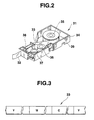
- the tape cartridge 31 contains a label tape 32 as a printing medium and an ink tape 33.
- a thermal head (not shown) of the printing unit 20 is driven to generate heat, the ink in the ink tape 33 is transferred to the label tape 32 for printing purposes.
- FIG. 2 shows the inside structure of the tape cartridge 31 with a transparent cover 43 (FIG. 4) which should be provided above a case 34 being removed away.
- a feed spool 35 for the label tape 32 a feed spool 36 for the ink tape 33 and a winding spool 37.
- a recess 38 is provided on the outside of the case 34 to dispose the thermal head therein.
- the label tape 32 and ink tape 33 are drawn into the recess 38 and pressed between the thermal head and a platen roller (not shown).
- a maximum number of three holes 39 is provided on the outer surface of the case 34 depending on the kind of the cartridge 31.
- the label tape 32 has a peelable paper strip attached through an adhesive to the back thereof.
- the ink tape 33 has a plurality of different ink (Y (yellow), M (magenta) and C (cyan)) areas arranged repeatedly in this order for multi-colored printing.
- the data storage 14 includes a printing data storage area 14a which stores as coded data printing data such as, for example, character, symbol, numeral and illustration data input by the key-in unit 11, a print color data storage area 14b which stores print color data indicative of the print color of the printing data, a background color data storage area 14c which stores data on the (background) color of the label tape 32 determined on the basis of the detection information from the cartridge detector 12, and an area (not shown) for storing other data set by the controller 21.
- coded data printing data such as, for example, character, symbol, numeral and illustration data input by the key-in unit 11
- a print color data storage area 14b which stores print color data indicative of the print color of the printing data
- a background color data storage area 14c which stores data on the (background) color of the label tape 32 determined on the basis of the detection information from the cartridge detector 12, and an area (not shown) for storing other data set by the controller 21.
- ROM 15 contains a program by which the controller 21, which may be composed of a microprocessor, controls the operation of the whole printer, and table data to be described later.
- the font memory 16 contains font pattern data for characters, symbols, numerals and illustrations.
- the display 18 is composed of a color liquid crystal display for display of a color image thereon.
- the display control unit 17 includes a VRAM (display RAM) 17a which contains display pattern data, controls the drive voltage of display 18 in accordance with the control of the controller 21 to display printing data, etc., in a specified color in the background having the same color as the label tape 32.
- VRAM display RAM
- the printing unit 20 has therein a cartridge accommodating space 41 (FIG. 4) in which a tape cartridge 31 is to be set, a printing mechanism (not shown) including a thermal head and a platen roller to melt and transfer an ink in the ink tape 33 to the label tape 32, a conveying mechanism (not shown) which conveys the ink tape 33, and a conveyer mechanism (not shown) which conveys the label tape 32, and prints the printing data on the printing medium under of the control of the print control unit 19.
- the printing unit 20 performs a three-time color superimposing printing operation on the label tape 32 with Y, M and C inks in the ink tape 33.
- the print control unit 19 controls the printing unit 20 so as to print printing data fed from the controller 21 and includes a printing pattern memory 19a in which a printing (dot) pattern is to be spread.
- the controller 21 may be composed of a microprocessor, and controls the operation of the whole printer, for example, the data inputting operation, printing operation, and displaying operation.
- SW5 denotes a switch which detects the opening/closing of a cover 42 for the cartridge accommodating space 41.
- Reference numerals 22 and 23 denote an internal battery in the printer and a power supply for feeding predetermined drive voltages to the respective elements of the printer of FIG. 1, respectively.
- the printing unit 20 has the cartridge accommodating space 41 and the cover 42 which covers the space 41.
- the cover 42 has a transparent window 43 and is hinged on the printer body.
- switches SW1-SW4 are provided within the cartridge accommodating space 41 and turned on/off depending on the presence/absence a tape cartridge 31 set therein and its kind.
- a maximum of three holes 39 are provided depending on the color of a label tape 32 contained in the cartridge 31 at positions corresponding to the switches SW2-SW4 on the outside of the tape cartridge 31.
- the switches SW2-SW4 opposing the holes 39 on the tape cartridge are off because their movable elements 46a-46c are not pressed or moved. Without holes 39, the movable elements 46a-46c are pressed and moved by the tape cartridge 31 and thus corresponding switches are turned on.
- the switches SW2-SW4 are discriminable, using the three switches SW2-SW4.
- holes 39 are provided at positions corresponding to the switches SW2 and SW4 and no hole 39 is provided at a position corresponding to switch SW3.
- the movable element 46b of switch SW3 is pressed and moved and the switch SW3 is turned on whereas the movable elements 46a and 46c of the switches SW2-SW4 are not pressed or moved, so that the switches SW2 and SW4 are off.
- the switches SW1 and SW3 produce voltage outputs.
- the output signals from the four switches SW1-SW4 are encoded by the encoder 13 and the resulting signal is output to the controller 21.
- a code signal "1010" is output from the encoder 13 to the controller 21.
- Table 1 shows the relationship between the presence/absence of a tape cartridge 31 in the cartridge accommodating space 41, kind of tape cartridge 31 and on/off states of switches SW1-SW4.
- Label tape color/set or unset (tape cartridge) SW1 SW2 SW3 SW4 white 1 0 0 0 orange 1 0 0 1 red 1 0 1 0 purple 1 0 1 1 black 1 1 0 0 blue 1 1 0 1 green 1 1 1 0 yellow 1 1 1 1 1 cartridge is unset 0 0 0 0 0 0 0
- Table 1 "1" and “0" represent that the switch is on and off, respectively.
- Table 1 is contained in ROM 14.
- the controller 21 determines the color of a label tape 32 contained in the tape cartridge 31 by comparing code data output from the encoder 13 and Table 1 contained in ROM 14.
- a switch SW5 is provided in the sidewall of the case to detect the opening/closing of the cover 42 for the cartridge accommodating space 41.
- the switch SW5 is turned on/off, respectively.
- Information on the opening/closing of the cover 42 detected by the switch SW5 is delivered to the controller 21, which controls the power supply 23 such that when the switch SW5 has detected the opening of the cover 42, the power supply 23 is not turned on in spite of the operation of the power supply key 12a whereas when the switch SW5 detects the opening of the cover 42 after the power supply 23 is turned on, supply of power to the respective elements of the printer is stopped.
- the user operates the power supply key 12a of the key-in unit 12 to turn on the power supply 23 of the printer.
- the controller 21 performs an initializing process in response to the turning on of the power supply (step S1) and receives a coded version of detection signals from the switches SW1-SW4 (step S2).
- the controller 21 determines the presence/absence of a tape cartridge 31 set and the color of its label tape 32, if any, from the received code signal by referring to Table 1 of ROM 14 (step S3).
- the controller 21 determines that at step S3 that no tape cartridge 31 is set, it displays a message "Please set a tape cartridge” on the display 18 through the display control unit 17 (step S4).
- the controller 21 determines at step S3 that a tape cartridge 31 is set, it stores as information on the (background) color of the label tape 32 the coded signal received from the cartridge detector 12 into the background color data storage area 14c of the data storage 14 (step S5). Further, the controller 21 displays the color of the label tape 32 of the set tape cartridge 31 throughout the whole display screen of the display 18 through the display control unit 17 on the basis of the background color data (step S6). For example, when the set tape cartridge 31 has a red label tape 32, the whole display screen is displayed in red, as shown in FIG. 6A. This processing is achieved, for example, by writing the displayed color throughout the whole VRAM 17a.
- the controller 21 waits for incoming printing data such as character data which the user wants to print and data on its specified printing color from the key-in unit 11 (step S7).
- the user operates the character keys lib and corresponding print color specifying keys 11 11c to input printing data and their print color data, respectively.
- the controller 21 determines at step S7 that character data and print color data have been input, it stores the input character data and corresponding print color data in the form of code data into the printing data storage area 14a and print color data storage area 14b, respectively, of the data storage 14 (step S8).
- the respective colors of all or a part of the input character string data may be specified or their respective print color may be specified later.
- this print color may be maintained for all character data which will be input thereafter until the next print color is specified newly.
- the controller 21 controls the display control unit 17 to read from the font memory 16 pattern data for the character data stored in the printing data storage area 14a and spreads on the VRAM 17a the read pattern data in the colors specified with the print color data stored in the print color data storage area 14b.
- displayed on the display screen are the input characters in the specified colors in the background having the same color as the label tape 32. That is, the background of the display screen having the same color as the label tape 32 and the printing data having the specified colors are combined or synthesized and displayed (step S9).
- the controller 21 determines whether the specified print color of the printing data is the same as the determined color of the label tape 32 (step S10) and further whether the specified print color of the printing data and the determined color of the label tape 32 belong to the same color system (step S11).
- step S10 the controller 21 displays a message "The same color. Please specify another color.” on the display 18 through the display control unit 17 (step S12).
- the controller 21 waits for the re-inputting operation of print color data from the key-in unit 11 by the user (step S13). If there is any re-input print color data, the controller 21 changes the print color data stored in the print color data area 14b of the data storage 14 (step S14). Control then returns to step S9, where the controller 21 changes the color of the printing data to the color of the re-input print color data and displays the printing data whose color has been changed in the same background color as the label tape 32 on the display screen.
- step S11 the controller 21 displays an alarm message "The same color system" along with a select screen "(1) The specified print color should be changed. (2) The specified color should not be changed.” on the display 18 through the display control unit 17 (step S15).
- the determination about this same color system is achieved, for example, by comparing the background color of the label tape 32 and the print color data by referring to a related one of Tables in ROM 14 one containing colors of the same color system as each of the colors of the label tapes 32.
- the controller 21 determines selection of a change of the specified print color and the re-inputting of the print color data by the user at step S16, the controller 21 changes the print color data stored in the print color data storage area 14b to the re-input print color data (step S17).
- Control then returns to step S9, where the controller 21 changes the print color data of the printing data to that of the re-input print color data and then displays the printing data in the changed color in the background having the same color as the label tape 32 on the display screen of the display 18.
- the user When the inputting operation of the character data ends and the input character data is to be printed, the user operates the printing key lid, which is then detected by the controller 21 at step S18.
- the controller 21 reads printing data stored in the printing data storage area 14a and the print color data stored in the print color data storage area 14b and feeds them to the print control unit 19, which then reads font pattern data for the character data from the font memory 16 and sequentially spreads on the basis of the fed data the respective printing (dot:) pattern data for yellow, magenta and cyan, which are the colors of inks in the ink tape 33, in the printing pattern memory 19a and controls the printing unit 20 to print the respective yellow, magenta, and cyan printing pattern data on the label tape 32 in a superimposing manner, using the ink tape 33 (step S19).
- the switch SW5 is turned off simultaneously with the opening of the cover 42. In this state, the controller 21 stops the supply of power from the power supply 23 to the respective elements concerned of the printer.
- the controller 21 receives a code signal again from the cartridge detector 12 and determines the color of the label tape 32 contained in the new set tape cartridge 31.
- the controller 21 rewrites the background color data set in the background color data storage area 14c of the data storage 14 to the determined color data, controls the display control unit 17 to rewrite the background color data spread in the VRAM 17a to the determined color data, and then returns to its regular processing of FIG. 5.
- the background of the display screen is displayed in the color of the label tape 32 contained in the tape cartridge 31 set in the tape printer.
- the user can immediately recognize the color of the label tape 32 contained in the tape cartridge 31 set in the tape printer. Since the printing data is displayed in the specified (print) color, the user can input the printing data while considering the layout of colors. Thus, there is no need for correcting the input data in accordance with the result of the printing.
- the print color of the printing data may be set automatically depending on the color of the label tape 32, for example, by referring to Table 2 below contained in ROM 14.
- Label tape color print color of printing data white black orange blue red green purple yellow black white blue orange green red yellow purple
- Table 2 contains colors of label tapes and print colors of printing data opposing the colors of label tapes in corresponding relationship. For example, when the controller 21 determines on the basis of the result of the detection of the cartridge detector 12 that the color of the label tape 32 is white, the controller 21 automatically sets black opposing white as the print color of the printing data by referring to Table 2. Similarly, when the controller 21 determines that the color of the label tape 32 is green, the controller automatically sets red as the print color of the printing data.
- reference symbols PI1-PI4 denote four photointerrupters provided in the cartridge accommodating space 41 in the printer 20.
- the tape cartridge 31 is inserted into the accommodating space 41 in the direction of arrow X such that an extension 50 of a cartridge side enters the inside of four U-like piled photointerrupters PI1-PI4 with the extension 50 having a maximum of three through holes 51 which are alignable with the corresponding light emitters and receivers of photointerrupters PI2-PI4. Since the extension 50 is inserted between the light emitters and corresponding receivers of the photointerrupters PI1-PI4.
- Table 3 data "1” and “0” represents that the light receiver of a photointerrupter concerned has a significant output and no significant one, respectively.
- Table 3 is contained in ROM 15. As described above, the three holes 51 are provided which are alignable with the photointerrupters PI2-PI4 in the extension 50 of the cartridge 31 of FIG. 7 and there is no hole which is alignable with the photointerrupter PI1. Thus, when the tape cartridge 31 is inserted into the cartridge accommodating space 41, the cartridge detector 12 encoder 13) outputs a coded signal "0111", which indicates that a yellow label tape is accommodated, by referring to Table 3.
- label tape 32 is illustrated as having any one of eight colors; white, orange, red, purple, black, blue, green and yellow, any other color may be used: for example, transparent, silver, gold, pink and any of their fluorescent colors.
- the background color of the display screen is illustrated as being displayed simultaneously with the time when the power supply is turned on and the tape cartridge 31 is released and set, the background color may be displayed, for example, only when a layout display mode for the display, etc., of the printing image is set.
- the inventive printer is not limited to this particular case.
- the present invention is applicable to printers which print any data on any printing medium, for example, word processors, personal computers connected to printers, etc.
- the determination of the color of a printing medium is not limited to the utilization of the turning on/off of switches, but may be performed by color sensors disposed adjacent to a printing medium.
Landscapes
- Printers Characterized By Their Purpose (AREA)
- Accessory Devices And Overall Control Thereof (AREA)
- Record Information Processing For Printing (AREA)
Claims (8)
- Imprimante de bande d'étiquettes comprenant :un moyen d'affichage (18) ayant un écran d'affichage de couleur ;un espace de logement de cartouche (41) pour loger de façon remplaçable une cartouche d'une pluralité de types de cartouche (31) contenant chacune une bande d'étiquettes (32) comme support d'enregistrement et une bande d'encre (33) ayant une pluralité d'encres pour l'impression en couleur, et chacune de ladite cartouche ayant une forme (39, 51) dépendante de la couleur de la bande d'étiquettes (32) contenue dans celle-ci ;un moyen d'entrée (11) pour introduire des données d'impression telles que des caractères/symboles etdes données de couleur d'impression pour spécifier une couleur d'impression des données d'impression ;un moyen de stockage de données (14) pour stocker des données d'impression et les données de couleur d'impression introduites par le moyen d'entrée (11) ;un moyen d'impression (20) pour imprimer sur la. bande d'étiquettes (32) les données d'impression stockées dans le moyen de stockage de données (14) dans la couleur d'impression spécifiée par les données de couleur d'impression stockées dans le moyen de stockage de données (14)en utilisant la bande d'encre (33) contenue dans la cartouche (31) logée dans l'espace de logement de cartouche (41),un moyen de détection (12) pour détecter la forme (39, 51) de la cartouche (31) logée dans l'espace de logement de cartouche (41) et pour fournir des informations indicatrices de la forme détectée,un moyen de détermination (21) pour déterminer la couleur de la bande d'encre (33) contenue dans la cartouche (31) logée dans l'espace de logement de cartouche (41), en utilisant les informations obtenues à partir du moyen de détection (12) ; etun moyen de commande d'affichage (17, 21) pour commander le moyen d'affichage (18) pour afficher l'arrière-plan de l'écran d'affichage de couleur du moyen d'affichage (18) dans la couleur de la bande d'étiquettes (32) qui est déterminée par le moyen de détermination (21), et pour afficher sur l'arrière-plan de l'écran d'affichage de couleur les données d'impression stockées dans le moyen de stockage de données (14) dans la couleur spécifiée par les données de couleur d'impression stockées dans le moyen de stockage de données (14).
- Imprimante selon la revendication 1, comprenant en outre :un second moyen de détermination (21) pour déterminer si la couleur d'impression des données d'impression spécifiées par les données de couleur d'impression stockées dans le moyen de stockage de données (14) coïncide avec la couleur de la bande d'étiquettes (32) déterminée par le moyen de détermination mentionné en premier (21) ; etun moyen de commande (21) sensible au second moyen de détermination (21) déterminant que la couleur d'impression des données d'impression spécifiées par les données de couleur d'impression stockées dans le moyen de stockage de données (14) coïncide avec la couleur de la bande d'étiquettes (32) déterminée par le moyen de détermination mentionné en premier (21) pour afficher un message à l'utilisateur pour spécifier une couleur d'impression différente.
- Imprimante selon la revendication 2, comprenant en outre :un premier moyen de commande d'affichage de message (19, 21), sensible au second moyen de détermination (21) déterminant que la couleur d'impression des données d'impression spécifiées par les données de couleur d'impression stockées dans le moyen de stockage de données (14) coïncide avec la couleur de la bande d'étiquettes (32) déterminée par le moyen de détermination mentionné en premier (21) pour commander le moyen d'affichage (20) pour afficher un message pour cet effet sur l'écran d'affichage et un message ordonnant à l'utilisateur d'introduire de nouveau les données de couleur d'impression.
- Imprimante selon la revendication 3, comprenant en outre :un premier moyen de changement de données (21), sensible au moyen d'entrée (11) introduisant de nouveau les données de couleur d'impression selon le message affiché sur le moyen d'affichage (20) par le premier moyen de commande d'affichage de message (19, 21) pour changer les données de couleur d'impression stockées dans le moyen de stockage de données (14) pour introduire de nouveau des données de couleur d'impression, et où :le second moyen de détermination (21) détermine si la couleur d'impression des données d'impression spécifiées par les données de couleur d'impression qui ont été changées par le premier moyen de changement de données (21) coïncide avec la couleur de la bande d'étiquettes déterminée par le moyen de détermination mentionné en premier (21).
- Imprimante selon la revendication 1, comprenant en outre :un moyen de stockage d'informations de couleur (15) qui contient des informations sur des couleurs appartenant au même système de couleur ;un troisième moyen de détermination (21) pour déterminer sur la base des informations de couleurs appartenant au même système de couleur stocké dans le moyen de stockage d'informations de couleur (15) si la couleur d'impression des données d'impression spécifiées par les données de couleur d'impression stockées dans le moyen de stockage de données (14) et la couleur de la bande d'étiquettes (32) déterminée par le moyen de détermination mentionné en premier (21) appartiennent au même système de couleur ; etun troisième moyen de commande d'affichage de message (19, 21), sensible au second moyen de détermination (21) déterminant que la couleur d'impression des données d'impression spécifiées par les données de couleur d'impression stockées dans le moyen de stockage de données (14) et la couleur de la bande d'étiquettes (32) déterminée par le moyen de détermination mentionné en premier (21) appartiennent au même système de couleur, pour commander le moyen d'affichage (20) pour afficher un message pour cet effet et un message que les données de couleur d'impression peuvent de nouveau être introduites.
- Imprimante selon la revendication 5, comprenant en outre :un second moyen de changement de données (21) sensible au moyen d'entrée (11b) introduisant de nouveau les données de couleur d'impression selon les messages affichés sur le moyen d'affichage (20) par le second moyen de commande d'affichage de message (19, 21) pour changer les données de couleur d'impression stockées dans le moyen de stockage de données (14) en données de couleur d'impression introduites de nouveau, et où :le troisième moyen de détermination (21) détermine si la couleur d'impression des données d'impression spécifiées par les données de couleur d'impression qui ont été changées par le second moyen de changement de données (21) coïncide avec la couleur de la bande d'étiquettes (32)déterminée par le moyen de détermination mentionné en premier (21).
- Imprimante selon la revendication 1, dans laquelle :le moyen de détection (12) comprend une pluralité de moyens de commutateurs (SW2 à SW4) qui sont adaptés pour être actionnés en fonction de la forme de la cartouche (31).
- Imprimante selon la revendication 1, dans laquelle :le moyen de détection (12) comprend une pluralité d'unités de photo-détections (P12 à SP14) qui sont adaptés pour être actionnés en fonction de la forme de la cartouche (31).
Applications Claiming Priority (3)
| Application Number | Priority Date | Filing Date | Title |
|---|---|---|---|
| JP29054795 | 1995-10-13 | ||
| JP7290547A JPH09109479A (ja) | 1995-10-13 | 1995-10-13 | 印刷装置 |
| JP290547/95 | 1995-10-13 |
Publications (3)
| Publication Number | Publication Date |
|---|---|
| EP0768185A2 EP0768185A2 (fr) | 1997-04-16 |
| EP0768185A3 EP0768185A3 (fr) | 1998-06-03 |
| EP0768185B1 true EP0768185B1 (fr) | 2002-03-20 |
Family
ID=17757448
Family Applications (1)
| Application Number | Title | Priority Date | Filing Date |
|---|---|---|---|
| EP96116188A Expired - Lifetime EP0768185B1 (fr) | 1995-10-13 | 1996-10-09 | Imprimantes affichant la couleur du moyen d'impression |
Country Status (7)
| Country | Link |
|---|---|
| US (1) | US5839837A (fr) |
| EP (1) | EP0768185B1 (fr) |
| JP (1) | JPH09109479A (fr) |
| KR (1) | KR0181362B1 (fr) |
| CN (1) | CN1075450C (fr) |
| DE (1) | DE69619923T2 (fr) |
| HK (1) | HK1001127A1 (fr) |
Families Citing this family (16)
| Publication number | Priority date | Publication date | Assignee | Title |
|---|---|---|---|---|
| US6485206B1 (en) * | 1999-09-14 | 2002-11-26 | Brother Kogyo Kabushiki Kaisha | Cassette and detecting device for installation thereof |
| JP3832164B2 (ja) * | 1999-12-08 | 2006-10-11 | コニカミノルタビジネステクノロジーズ株式会社 | 画像形成装置 |
| US6793322B1 (en) * | 2003-05-15 | 2004-09-21 | Eastman Kodak Company | Method of printing multi-color image |
| US6692104B1 (en) * | 2003-05-21 | 2004-02-17 | Eastman Kodak Company | Method of printing multi-color composition |
| GB0315148D0 (en) * | 2003-06-27 | 2003-08-06 | Esselte Nv | Tape printing apparatus and tape cassette |
| US7422384B2 (en) * | 2004-03-17 | 2008-09-09 | Hewlett-Packard Development, L.P. | System and a method for printing small print jobs |
| JP5071201B2 (ja) * | 2008-03-31 | 2012-11-14 | ブラザー工業株式会社 | 印刷プレビューデータ作成装置、印刷プレビューデータ作成プログラム及びコンピュータ読み取り可能な記録媒体 |
| CN101850665B (zh) * | 2009-03-31 | 2015-01-14 | 兄弟工业株式会社 | 带盒 |
| JP5609353B2 (ja) * | 2010-07-16 | 2014-10-22 | セイコーエプソン株式会社 | テープ印刷装置 |
| JP6011113B2 (ja) * | 2012-07-27 | 2016-10-19 | ブラザー工業株式会社 | 印刷制御装置および印刷制御プログラム |
| JP2014191552A (ja) * | 2013-03-27 | 2014-10-06 | Seiko Epson Corp | 印刷システムおよび情報処理装置 |
| JP6330990B2 (ja) * | 2013-08-29 | 2018-05-30 | セイコーエプソン株式会社 | 画像表示装置、記録装置、プログラム及び表示方法 |
| JP6380159B2 (ja) | 2015-02-23 | 2018-08-29 | セイコーエプソン株式会社 | 情報処理装置、情報処理装置の表示方法およびプログラム |
| KR20170090824A (ko) * | 2016-01-29 | 2017-08-08 | 삼성전자주식회사 | 전자장치 및 그 제어방법 |
| JP6572928B2 (ja) * | 2017-03-21 | 2019-09-11 | 京セラドキュメントソリューションズ株式会社 | 情報処理装置及び画像形成システム |
| DE102017215435A1 (de) * | 2017-09-04 | 2019-03-07 | Krones Ag | Behälterbehandlungsanlage zum Behandeln von Behältern |
Family Cites Families (13)
| Publication number | Priority date | Publication date | Assignee | Title |
|---|---|---|---|---|
| US4824269A (en) * | 1987-03-13 | 1989-04-25 | Karel Havel | Variable color display typewriter |
| JP2723992B2 (ja) * | 1989-09-08 | 1998-03-09 | 株式会社日立製作所 | 熱転写プリンタ |
| JPH03244582A (ja) * | 1990-02-23 | 1991-10-31 | Citizen Watch Co Ltd | プリンタのカラー切替表示装置 |
| JPH07181756A (ja) * | 1991-05-27 | 1995-07-21 | Ricoh Co Ltd | 記録紙の種類検知機能を備えた画像形成装置 |
| CA2085550C (fr) * | 1991-12-19 | 1999-07-06 | Kentaro Yano | Methode pour commander un appareil d'enregistrement a jet d'encre selon l'information a enregistrer et appareil d'enregistrement utilisant cette methode |
| JPH06106784A (ja) * | 1992-09-29 | 1994-04-19 | Brother Ind Ltd | テープ印字装置 |
| JP3370740B2 (ja) * | 1993-07-23 | 2003-01-27 | ブラザー工業株式会社 | テープユニット、テープカセット並びにテープ印字装置 |
| JP3378622B2 (ja) * | 1993-09-21 | 2003-02-17 | ブラザー工業株式会社 | テープ印刷装置 |
| JPH07148918A (ja) * | 1993-12-01 | 1995-06-13 | Canon Inc | プリンタ内蔵コンピュータ |
| JPH07179013A (ja) * | 1993-12-24 | 1995-07-18 | Toshiba Corp | リボンカセットの種類判定方法及び印刷装置 |
| EP0661656B1 (fr) * | 1993-12-29 | 1999-09-29 | Brother Kogyo Kabushiki Kaisha | Imprimante pour ruban |
| US6035351A (en) * | 1994-01-21 | 2000-03-07 | International Business Machines Corporation | Storage of user defined type file data in corresponding select physical format |
| US5620268A (en) * | 1995-03-29 | 1997-04-15 | Brother Kogyo Kabushiki Kaisha | Composite cassette including a tape cassette and a ribbon cassette |
-
1995
- 1995-10-13 JP JP7290547A patent/JPH09109479A/ja active Pending
-
1996
- 1996-10-09 US US08/727,975 patent/US5839837A/en not_active Expired - Fee Related
- 1996-10-09 EP EP96116188A patent/EP0768185B1/fr not_active Expired - Lifetime
- 1996-10-09 DE DE69619923T patent/DE69619923T2/de not_active Expired - Fee Related
- 1996-10-11 KR KR1019960045257A patent/KR0181362B1/ko not_active IP Right Cessation
- 1996-10-14 CN CN96120372A patent/CN1075450C/zh not_active Expired - Fee Related
-
1997
- 1997-12-29 HK HK97102648A patent/HK1001127A1/xx not_active IP Right Cessation
Also Published As
| Publication number | Publication date |
|---|---|
| CN1075450C (zh) | 2001-11-28 |
| JPH09109479A (ja) | 1997-04-28 |
| EP0768185A2 (fr) | 1997-04-16 |
| HK1001127A1 (en) | 1998-05-29 |
| EP0768185A3 (fr) | 1998-06-03 |
| CN1153110A (zh) | 1997-07-02 |
| DE69619923D1 (de) | 2002-04-25 |
| KR0181362B1 (ko) | 1999-05-15 |
| KR970020427A (ko) | 1997-05-28 |
| DE69619923T2 (de) | 2002-07-25 |
| US5839837A (en) | 1998-11-24 |
Similar Documents
| Publication | Publication Date | Title |
|---|---|---|
| EP0768185B1 (fr) | Imprimantes affichant la couleur du moyen d'impression | |
| US6283647B1 (en) | Bar code printer that automatically sets one bar color in response to another bar color | |
| US5447383A (en) | Tape printing apparatus having manual tape cutting device with suspension of printing | |
| KR100239156B1 (ko) | 인쇄장치 및 인쇄방법 | |
| US5920684A (en) | Hand-held label printer with dedicated function keys for creating and altering labels | |
| JP3335433B2 (ja) | テープカセット | |
| EP0931670B1 (fr) | Imprimante couleur | |
| US5706030A (en) | Compact data input device having transparent touch panel | |
| EP0862517B1 (fr) | Imprimantes de bande | |
| US5967675A (en) | Printing apparatus | |
| US5383731A (en) | Printing device having a print media detector | |
| US5885012A (en) | Printing apparatus | |
| JPH0647937A (ja) | サーマル印刷装置 | |
| US20030219300A1 (en) | Printing apparatus | |
| KR100360961B1 (ko) | 테이프 인쇄 장치 및 테이프 인쇄 방법 | |
| JP3045054B2 (ja) | テープ状ラベル作成装置 | |
| US20050007606A1 (en) | Printing apparatus, display method thereof, printing system, display method thereof, program, and memory medium | |
| US6296406B1 (en) | Label-making apparatus and method | |
| JPH09183427A (ja) | 印刷装置及びラベルテープ | |
| KR20040048842A (ko) | 테이프 인쇄 장치 및 그 인쇄 제어 방법과 기억 매체 | |
| JPH06171125A (ja) | サーマル印刷装置 | |
| US20010035964A1 (en) | Tape cartridge, tape printing method, tape printing apparatus, and label-producing method | |
| JPS63120678A (ja) | 印字機能を有する情報処理装置 | |
| JP3487110B2 (ja) | カラー印刷装置 | |
| EP0747228B1 (fr) | Imprimante d'étiquettes et méthode pour imprimer des étiquettes identiques multicolores |
Legal Events
| Date | Code | Title | Description |
|---|---|---|---|
| PUAI | Public reference made under article 153(3) epc to a published international application that has entered the european phase |
Free format text: ORIGINAL CODE: 0009012 |
|
| 17P | Request for examination filed |
Effective date: 19961009 |
|
| AK | Designated contracting states |
Kind code of ref document: A2 Designated state(s): BE DE FR GB |
|
| PUAL | Search report despatched |
Free format text: ORIGINAL CODE: 0009013 |
|
| RAP1 | Party data changed (applicant data changed or rights of an application transferred) |
Owner name: CASIO COMPUTER CO., LTD. |
|
| AK | Designated contracting states |
Kind code of ref document: A3 Designated state(s): BE DE FR GB |
|
| 17Q | First examination report despatched |
Effective date: 19990531 |
|
| GRAG | Despatch of communication of intention to grant |
Free format text: ORIGINAL CODE: EPIDOS AGRA |
|
| GRAG | Despatch of communication of intention to grant |
Free format text: ORIGINAL CODE: EPIDOS AGRA |
|
| GRAH | Despatch of communication of intention to grant a patent |
Free format text: ORIGINAL CODE: EPIDOS IGRA |
|
| GRAH | Despatch of communication of intention to grant a patent |
Free format text: ORIGINAL CODE: EPIDOS IGRA |
|
| REG | Reference to a national code |
Ref country code: GB Ref legal event code: IF02 |
|
| GRAA | (expected) grant |
Free format text: ORIGINAL CODE: 0009210 |
|
| AK | Designated contracting states |
Kind code of ref document: B1 Designated state(s): BE DE FR GB |
|
| REF | Corresponds to: |
Ref document number: 69619923 Country of ref document: DE Date of ref document: 20020425 |
|
| ET | Fr: translation filed | ||
| ET | Fr: translation filed | ||
| PG25 | Lapsed in a contracting state [announced via postgrant information from national office to epo] |
Ref country code: GB Free format text: LAPSE BECAUSE OF NON-PAYMENT OF DUE FEES Effective date: 20021009 |
|
| PG25 | Lapsed in a contracting state [announced via postgrant information from national office to epo] |
Ref country code: BE Free format text: LAPSE BECAUSE OF NON-PAYMENT OF DUE FEES Effective date: 20021031 |
|
| PLBE | No opposition filed within time limit |
Free format text: ORIGINAL CODE: 0009261 |
|
| STAA | Information on the status of an ep patent application or granted ep patent |
Free format text: STATUS: NO OPPOSITION FILED WITHIN TIME LIMIT |
|
| 26N | No opposition filed |
Effective date: 20021223 |
|
| BERE | Be: lapsed |
Owner name: *CASIO COMPUTER CO. LTD Effective date: 20021031 |
|
| PG25 | Lapsed in a contracting state [announced via postgrant information from national office to epo] |
Ref country code: DE Free format text: LAPSE BECAUSE OF NON-PAYMENT OF DUE FEES Effective date: 20030501 |
|
| GBPC | Gb: european patent ceased through non-payment of renewal fee |
Effective date: 20021009 |
|
| PG25 | Lapsed in a contracting state [announced via postgrant information from national office to epo] |
Ref country code: FR Free format text: LAPSE BECAUSE OF NON-PAYMENT OF DUE FEES Effective date: 20030630 |
|
| REG | Reference to a national code |
Ref country code: FR Ref legal event code: ST |
|
| REG | Reference to a national code |
Ref country code: HK Ref legal event code: WD Ref document number: 1013415 Country of ref document: HK |