EP0767478A1 - Circuit de sécurité - Google Patents
Circuit de sécurité Download PDFInfo
- Publication number
- EP0767478A1 EP0767478A1 EP95117767A EP95117767A EP0767478A1 EP 0767478 A1 EP0767478 A1 EP 0767478A1 EP 95117767 A EP95117767 A EP 95117767A EP 95117767 A EP95117767 A EP 95117767A EP 0767478 A1 EP0767478 A1 EP 0767478A1
- Authority
- EP
- European Patent Office
- Prior art keywords
- signal
- multivibrator
- safety circuit
- driver stage
- relays
- Prior art date
- Legal status (The legal status is an assumption and is not a legal conclusion. Google has not performed a legal analysis and makes no representation as to the accuracy of the status listed.)
- Granted
Links
Images
Classifications
-
- F—MECHANICAL ENGINEERING; LIGHTING; HEATING; WEAPONS; BLASTING
- F16—ENGINEERING ELEMENTS AND UNITS; GENERAL MEASURES FOR PRODUCING AND MAINTAINING EFFECTIVE FUNCTIONING OF MACHINES OR INSTALLATIONS; THERMAL INSULATION IN GENERAL
- F16P—SAFETY DEVICES IN GENERAL; SAFETY DEVICES FOR PRESSES
- F16P3/00—Safety devices acting in conjunction with the control or operation of a machine; Control arrangements requiring the simultaneous use of two or more parts of the body
- F16P3/18—Control arrangements requiring the use of both hands
- F16P3/20—Control arrangements requiring the use of both hands for electric control systems
-
- H—ELECTRICITY
- H01—ELECTRIC ELEMENTS
- H01H—ELECTRIC SWITCHES; RELAYS; SELECTORS; EMERGENCY PROTECTIVE DEVICES
- H01H47/00—Circuit arrangements not adapted to a particular application of the relay and designed to obtain desired operating characteristics or to provide energising current
- H01H47/002—Monitoring or fail-safe circuits
- H01H47/004—Monitoring or fail-safe circuits using plural redundant serial connected relay operated contacts in controlled circuit
- H01H47/005—Safety control circuits therefor, e.g. chain of relays mutually monitoring each other
Definitions
- the invention relates to a safety circuit with an actuating device for electrical devices, the actuating device being operable by means of two buttons or contact sets.
- electrical devices is to be understood as a versatile field of application, i. That is, the invention can be applied to all electrical safety devices with two separately monitored electrical buttons or contact sets, such as light grids, protective doors, for example on machine systems, emergency stop monitors, limit switching monitors, floor mats, light curtains and the like. Examples of machine systems include presses, punching devices, milling machines, lathes or elevators.
- the electrical Safety circuit works correctly, so that it is only possible to switch through to the consumer, ie switch on the dangerous operating state, but that, on the other hand, switching through is definitely prevented if any fault occurs within the circuit.
- the previously known electrical safety circuits either do not meet all the safety criteria or they are designed in such a complicated and complex manner that they require a very high cost and a safety risk can also be seen in the complexity of the construction.
- the invention has for its object to provide a generally suitable safety circuit that is very simple and clearly designed and therefore means low costs, but which withstands all safety criteria including the avoidance of any manipulation.
- the safety circuit consists essentially of two modules, namely a driver stage and an astable multivibrator or a multivibrator with the features specified in claim 1.
- An advantageous embodiment of the invention is that a capacitor is provided, which is dimensioned such that it stores the energy in the rest position, which is required to energize the flip-flop or the multivibrator during the actuation time of both buttons of a maximum of 500 ms supply.
- the driver stage is supplied with voltage V + and V- via the make contacts and the relays are activated.
- the capacitor is integrated in the multivibrator.
- the astable flip-flop or multivibrator square-wave signals with a slope produces up to 10 microseconds, preferably less than 1 s, in particular, a duty cycle, there is a T to 50% T of 50%.
- a first diode is arranged between the first button and the driver stage and a second diode between the second button and the driver stage, the diodes blocking the current flow to the driver stage when the buttons are not actuated.
- the square-wave signals of the multivibrator or multivibrator control the driver stage in such a way that the square-wave signals are alternately high or low, so that either the first or the second relay is energized.
- the flip-flop or the multivibrator are supplied via the relays when the relays are energized.
- the two complementary square-wave signals of the same length are constant and inverse to one another.
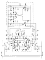
- the safety circuit shown in the drawing consists essentially of a driver stage 2 according to the rectangular dash-dotted line and a flip-flop or a multivibrator 1, which is also enclosed in the drawing by a rectangular dash-dotted line and to the driver stage 2, as explained in detail below is connected.
- Driver stage 2 interacts with two buttons S1 and S2 of an actuating device, not shown in detail, for example a two-hand actuation.
- the pushbuttons S1 and S2 should be operated at the same time if possible, at least within the short actuation time explained in more detail below.
- the driver stage 2 is supplied with the electrical voltage V + and V- via the buttons S1 and S2.
- Driver stage 2 has two PNP transistors Q1 and Q2 and two NPN transistors Q3 and Q4.
- the bases of the PNP transistor Q2 and the NPN transistor Q4 are connected to one another via a line 3, in which line 3 two resistors R2 and R4 and two Zener diodes Z2 and Z4 are connected in series.
- a line 4 is connected between the Zener diodes Z2 and Z4, which are connected in the same direction, in their forward direction from the resistor R4 to the resistor R2, which connects the driver stage 2 with the trigger circuit or the multivibrator 1 and that was explained in more detail below Signal 1 transmits, the line 4 in the multivibrator being connected to a line 5 which connects the resistor R6 to the collector of the transistor Q5.
- the collector of the PNP transistor Q2 is connected via a line 6 to the collector of the NPN transistor Q4.
- the emitter of the NPN transistor Q4 is in turn connected to the emitter of the NPN transistor Q3, the collector of which is connected via a line 7 to the collector of the PNP transistor Q1 is connected.
- the emitter of the PNP transistor Q1 is also connected to the emitter of the PNP transistor Q2.
- the PNP transistor Q1 and the NPN transistor Q3 are also connected via a line 8, which is connected to the bases of the aforementioned transistors Q1 and Q3, respectively.
- Two resistors R1 and R3 are arranged in line 8, between which Zener diodes Z1 and Z3 are connected.
- a line 9 is connected between the Zener diodes Z1 and Z3, which connects the line 8 in the driver stage 2 with a line 10 in the flip-flop or in the multivibrator 1, the line 10 between the resistor R11 and the collector of the NPN transistor Q6 runs.
- Signal 2 which will be explained below, is transmitted via line 9.
- the second relay-diode combination consists of a line 12, in which a diode V7 and a relay K2 are connected in series, the diode V7 on the collector side of the PNP transistor Q2 and the relay K2 on the collector side of the NPN transistor Q3 and the forward direction of the diode V7 runs from the collector of the PNP transistor Q2 to the collector of the NPN transistor Q3.
- a freewheeling diode V6 is also connected in parallel with the relay K2, the forward direction of which runs counter to the forward direction of the diode V7.
- the button S1 which in this example is equipped with a double contact, namely an NC contact s1ö and a NO contact s1s, is connected to the driver stage 2 via a line 13.
- the button S2 which is also equipped with a double contact, namely an NC contact s2ö and a NO contact s2s, is connected to the driver stage 2 via a line 14.
- Opener contacts a1ö and k2ö of relays K1 and K2 are arranged in lines 13 and 14, which also lead to the flip-flop or multivibrator 1, a diode V10 being connected to the normally closed contact k1ö and a diode V11 connected to the normally closed contact k2ö, the forward direction of which are oriented in opposite directions.
- further lines 17 and 18 run parallel to the lines 13 and 14, which likewise connect the button S1 on the one hand and the button S2 on the other hand to the flip-flop or the multivibrator 1.
- NO contacts k2s and k1s of the relays K2 and K1 are provided.
- the normally open contacts k2s and k1s are also connected upstream of diodes V9 and V12, which in turn are oriented in opposite directions with respect to their forward direction, the diodes V9 and V10 on the one hand and the diodes V11 and V12 on the other hand also being oriented in opposite directions.
- the driver stage 2 is connected via a line 21 to the line 13, the line 21 being connected between the emitters of the PNP transistors Q1 and Q2 and having a diode V1, the forward direction of which from the push button S1 to the connecting line between the emitters of the PNP Transistors Q1 and Q2 is aligned.
- a line 22 is provided which also has a diode V8 and which is connected on the emitter side to the NPN transistors Q3 and Q4, the diode V8 passing its direction from the emitters of the NPN transistors Q3 and Q4 to line 14.
- the flip-flop or multivibrator 1 has two NPN transistors Q5 and Q6, the bases of which are each connected between a resistor R5 or R12 and a diode V15 or V14.
- the collector of NPN transistor Q5 is connected in series with a resistor R6, whereas the collector of NPN transistor Q6 is connected in series with resistor R11.
- Resistor R6 is connected in parallel with two resistors R7 and R8 and resistor R11 is connected in parallel with two resistors R9 and R10.
- a diode V13 is connected between the resistors R6 and R7 and a diode V16 is connected between the resistors R10 and R11, the flow direction of the diode V13 from the resistor R7 to the resistor R6 and the flow direction of the diode V16 from the resistor R10 to the resistor R11.
- a capacitor C1 is connected between the resistors R7 and R8 and a capacitor C2 is connected between the resistors R9 and R10, the resistors R8 and R9 being connected in series with the diodes V14 and V 15, the direction of flow of which towards the bases of the NPN -Transistors Q5 and Q6 runs.
- a capacitor C3 and a resistor R13 are also connected in parallel with the resistor R11, the positive plate of the capacitor C3 being arranged on the side of the resistor R11 and the negative plate of the capacitor C3 being arranged on the side of the resistor R13, which has the emitter of the NPN transistor Q6 on the output side and the resistor R12 connected in parallel with it.
- the safety circuit uses direct current is operated. If the buttons S1 and S2 of the actuation device, for example a two-hand operation, are not pressed, the safety circuit is in the rest position. Via the closed contacts of the connection, referred to simply as ESB (external start condition), with feedback circuits known per se, namely the connection of the safety circuit to the rest of the machine control system, for example a dangerous metalworking machine, furthermore via the break contact k2ö of the relay K2, the diode V11 and the break contact s2ö of the button S2, the flip-flop or the multivibrator 1 is supplied with the voltage V-. Via the break contact k1ö of the relay K1, the diode V10 and the break contact s1ö of the button S1, the flip-flop or the multivibrator 1 is set to voltage V +.
- ESB internal start condition
- the flip-flop or multivibrator 1 swings in this state and generates two square-wave signals, namely signal 1 and signal 2, which are complementary and inverse to one another and each have the same length of time.
- the capacitor C3 absorbs or stores the energy which it needs in order to supply the flip-flop or the multivibrator 1 in an actuation time of the buttons S1 and S2 of a maximum of 500 ms. If the two buttons S1 and S2 are not actuated within this actuation time, i.e. practically simultaneously, the capacitor C3 is discharged prematurely, so that the multivibrator 1 or multivibrator 1 would no longer supply the relays K1 and K2, so that the further process the safety circuit would be interrupted.
- the diodes V1 and V8 block the current flow for the driver stage 2, so that the relays K1 and K2 are not energized. If a break contact k1ö and k2ö of the relays K1 or K2 are not closed in this state, the flip-flop or the multivibrator 1 would not work. Since the relays K1 and K2 positive relays, a possible contact failure is discovered here.
- driver stage 2 When pushbuttons S1 and S2 are actuated within the actuation time of 500 ms, driver stage 2 is supplied with voltage V + and V- via make contacts s1s and s2s. The diodes V1 and V8 are now polarized in the direction of flow. In this state, the energy stored in capacitor C3 supplies the flip-flop or multivibrator 1 for the maximum actuation time of 500 ms.
- relays K1 and K2 are activated and supply the flip-flop or multivibrator 1 with voltage via diodes V9 and V12.
- the square-wave signals signal 1 and signal 2 of the multivibrator or multivibrator 1 control the driver stage 2 as follows:
- signal 1 is high (high) and signal 2 low (low), as a result of which the transistors Q1 and Q 4 conduct and the relay K1 is excited, which also switches the contacts of the relay accordingly.
- signal 1 is low (low) and signal 2 is high (high), so that transistors Q2 and Q3 conduct and relay K2 is energized, so that its contacts switch accordingly.
- the flip-flop or the multivibrator 1 is supplied via the make contacts k1s and k2s of the relays K1 and K2.
- the current flows from A1 via the normally open contact s1s of the button S1, the diode V1, the transistor Q1, the diode V4 through the relay K1 to the transistor Q4 and from the transistor Q4 via the diode V8 and the normally open contact s2s of the button S2 to A1.
- the relay K1 is energized.
- the current flows from A1 via the normally open contact s1s of the button S1, the diode V1 to the transistor Q2 and from the transistor Q2 via the diode V7 through the relay K2 and from there via the transistor Q3 to the diode V8 to the normally open contact s2s of the button S2 to flow to A2.
- the relay K2 is energized.
- the frequency of the multivibrator or multivibrator 1 is preferably 1000 Hz and thus changes the state of the signals signal 1 and signal 2 every 0.5 ms. Due to the delay time of the relays K1 and K2 and the magnetic energy stored in the respective relay coil, which maintains the current flow of the mutual induction through the relay coils during the control breaks via the freewheeling diode V5 for relay K1 and the freewheeling diode V6 for relay K2 and K2 tightened. This state remains until the buttons S1 and S2 are released. Now the diodes V1 and V8 block the current flow and the driver stage 2 is no longer supplied with voltage. The relays K1 and K2 drop out, which sets the rest position of the device or the safety circuit.
- either the transistor Q5 or the transistor Q6 is turned on in the flip-flop or in the multivibrator 1 when it is switched on.
- the collector of transistor Q6 is at low potential in accordance with signal 2.
- a charging current, which is defined by the resistor R9, thus flows via the capacitor C2.
- the base of transistor Q5 is initially at low potential, transistor Q5 being blocked.
- the collector of transistor Q5 is correspondingly the signal 1 high potential.
- the charge current flowing through capacitor C2 increases the potential at the base of transistor Q5 until transistor Q5 turns on.
- Signal 1 drops to low potential and at the same time a charging current, which is defined by resistor R8, flows through capacitor C1.
- transistor Q6 falls back to low potential and blocks transistor Q6, causing signal 2 to go high.
- the diodes V13, V14, V15 and V16 present in the safety circuit described above serve to accelerate the switching times of signals 1 and 2.
- the operating points are set by resistors R5 and R12.
- the following error analysis shows further features and effects of the safety circuit according to the invention. Above all, the error analysis shows that all conceivable errors from pushbuttons S1, S2 to the input of the ESB (external star condition) of the external machine control system are recognized and that switching through is prevented in any case.
- the dangerous movement to be protected is triggered redundantly via two unsigned outputs of the safety device.
- the redundant outputs can be designed both as normally open circuits and as normally closed circuits.
Landscapes
- Engineering & Computer Science (AREA)
- General Engineering & Computer Science (AREA)
- Mechanical Engineering (AREA)
- Relay Circuits (AREA)
- Keying Circuit Devices (AREA)
- Control Of Combustion (AREA)
- Air Bags (AREA)
- Cookers (AREA)
Priority Applications (7)
| Application Number | Priority Date | Filing Date | Title |
|---|---|---|---|
| EP95117767A EP0767478B1 (fr) | 1995-10-04 | 1995-11-11 | Circuit de sécurité |
| AT95117767T ATE185448T1 (de) | 1995-10-04 | 1995-11-11 | Sicherheitsschaltung |
| DE59506997T DE59506997D1 (de) | 1995-10-04 | 1995-11-11 | Sicherheitsschaltung |
| CA002187101A CA2187101C (fr) | 1995-10-04 | 1996-10-03 | Circuit de securite |
| MXPA/A/1996/004549A MXPA96004549A (en) | 1995-10-04 | 1996-10-03 | Circuito de seguri |
| US08/725,715 US5771146A (en) | 1995-10-04 | 1996-10-04 | Safety circuit |
| JP8264941A JPH09223427A (ja) | 1995-10-04 | 1996-10-04 | 電気器具用作動装置を有する安全回路 |
Applications Claiming Priority (3)
| Application Number | Priority Date | Filing Date | Title |
|---|---|---|---|
| EP95115622 | 1995-10-04 | ||
| DE95115622 | 1995-10-04 | ||
| EP95117767A EP0767478B1 (fr) | 1995-10-04 | 1995-11-11 | Circuit de sécurité |
Publications (2)
| Publication Number | Publication Date |
|---|---|
| EP0767478A1 true EP0767478A1 (fr) | 1997-04-09 |
| EP0767478B1 EP0767478B1 (fr) | 1999-10-06 |
Family
ID=26138842
Family Applications (1)
| Application Number | Title | Priority Date | Filing Date |
|---|---|---|---|
| EP95117767A Expired - Lifetime EP0767478B1 (fr) | 1995-10-04 | 1995-11-11 | Circuit de sécurité |
Country Status (6)
| Country | Link |
|---|---|
| US (1) | US5771146A (fr) |
| EP (1) | EP0767478B1 (fr) |
| JP (1) | JPH09223427A (fr) |
| AT (1) | ATE185448T1 (fr) |
| CA (1) | CA2187101C (fr) |
| DE (1) | DE59506997D1 (fr) |
Cited By (2)
| Publication number | Priority date | Publication date | Assignee | Title |
|---|---|---|---|---|
| WO2001039229A1 (fr) * | 1999-11-25 | 2001-05-31 | Siemens Aktiengesellschaft | Dispositif a deux contacteurs couples en serie |
| EP2551874A1 (fr) * | 2011-07-28 | 2013-01-30 | PHOENIX CONTACT GmbH & Co. KG | Commutateur de commande électrique à relais |
Families Citing this family (1)
| Publication number | Priority date | Publication date | Assignee | Title |
|---|---|---|---|---|
| DE19715098B4 (de) * | 1997-04-11 | 2004-12-23 | Schneider Electric Gmbh | Überwachungsschaltung |
Citations (3)
| Publication number | Priority date | Publication date | Assignee | Title |
|---|---|---|---|---|
| DE1926607A1 (de) * | 1969-05-24 | 1970-12-17 | Ako Werke Gmbh & Co | Zweihandschalteinrichtung zum Ein- und Ausschalten von elektrischen Lasten |
| EP0105054A1 (fr) * | 1982-10-01 | 1984-04-11 | Square D Starkstrom GmbH | Circuit pour le contrôle actif d'interrupteurs de fin de course rangés par paires |
| DE3600173A1 (de) * | 1986-01-07 | 1987-07-09 | Rohr Manfred | Zweikanalige, mit gleichstrom betriebene zweihandschaltung fuer kraftbetriebene pressen od.dgl. |
Family Cites Families (6)
| Publication number | Priority date | Publication date | Assignee | Title |
|---|---|---|---|---|
| DE1463215B2 (de) * | 1963-02-20 | 1970-12-17 | Th. Kieserling & Albrecht, 565O Solingen | Elektrische Sicherheitssteuerung für Pressen, Stanzen oder dgl |
| US3371254A (en) * | 1965-10-01 | 1968-02-27 | Harold T. Hagfors | Safety control system |
| US3793533A (en) * | 1973-03-16 | 1974-02-19 | Precision Electronic Component | Electrical safety control circuit |
| US3914621A (en) * | 1974-10-07 | 1975-10-21 | Gen Electric | Circuit for enabling safe actuation of a machine |
| US4412268A (en) * | 1981-10-02 | 1983-10-25 | Dart Industries Inc. | Safety switch system for industrial machines |
| US5235217A (en) * | 1991-07-24 | 1993-08-10 | Isb Ltd. | Capacitive press control actuation system |
-
1995
- 1995-11-11 EP EP95117767A patent/EP0767478B1/fr not_active Expired - Lifetime
- 1995-11-11 AT AT95117767T patent/ATE185448T1/de not_active IP Right Cessation
- 1995-11-11 DE DE59506997T patent/DE59506997D1/de not_active Expired - Lifetime
-
1996
- 1996-10-03 CA CA002187101A patent/CA2187101C/fr not_active Expired - Fee Related
- 1996-10-04 US US08/725,715 patent/US5771146A/en not_active Expired - Lifetime
- 1996-10-04 JP JP8264941A patent/JPH09223427A/ja active Pending
Patent Citations (3)
| Publication number | Priority date | Publication date | Assignee | Title |
|---|---|---|---|---|
| DE1926607A1 (de) * | 1969-05-24 | 1970-12-17 | Ako Werke Gmbh & Co | Zweihandschalteinrichtung zum Ein- und Ausschalten von elektrischen Lasten |
| EP0105054A1 (fr) * | 1982-10-01 | 1984-04-11 | Square D Starkstrom GmbH | Circuit pour le contrôle actif d'interrupteurs de fin de course rangés par paires |
| DE3600173A1 (de) * | 1986-01-07 | 1987-07-09 | Rohr Manfred | Zweikanalige, mit gleichstrom betriebene zweihandschaltung fuer kraftbetriebene pressen od.dgl. |
Cited By (4)
| Publication number | Priority date | Publication date | Assignee | Title |
|---|---|---|---|---|
| WO2001039229A1 (fr) * | 1999-11-25 | 2001-05-31 | Siemens Aktiengesellschaft | Dispositif a deux contacteurs couples en serie |
| US6870723B1 (en) | 1999-11-25 | 2005-03-22 | Siemens Aktiengesellschaft | Configuration comprising two contactors connected in series |
| EP2551874A1 (fr) * | 2011-07-28 | 2013-01-30 | PHOENIX CONTACT GmbH & Co. KG | Commutateur de commande électrique à relais |
| DE102011052251A1 (de) * | 2011-07-28 | 2013-01-31 | Phoenix Contact Gmbh & Co. Kg | Elektrische Relaisansteuerschaltung |
Also Published As
| Publication number | Publication date |
|---|---|
| CA2187101C (fr) | 2000-08-29 |
| EP0767478B1 (fr) | 1999-10-06 |
| US5771146A (en) | 1998-06-23 |
| CA2187101A1 (fr) | 1997-04-05 |
| ATE185448T1 (de) | 1999-10-15 |
| DE59506997D1 (de) | 1999-11-11 |
| JPH09223427A (ja) | 1997-08-26 |
| MX9604549A (es) | 1998-10-31 |
Similar Documents
| Publication | Publication Date | Title |
|---|---|---|
| DE10011211B4 (de) | Sicherheitsschaltgerät und Sicherheitsschaltgeräte-System | |
| EP1493064B1 (fr) | Appareil de coupure, protegee contre les erreurs, d'un consommateur electrique, notamment dans les installations de production industrielle | |
| DE19813143A1 (de) | Notfallabschalteinrichtung für Motoren | |
| DE2711416C2 (de) | Anordnung zur Anzeige des Schaltungszustandes der Schalter | |
| DE102008002758B4 (de) | Relaisschaltung | |
| DE2007664A1 (de) | Steuerschaltung für Maschinen | |
| EP0767478B1 (fr) | Circuit de sécurité | |
| DE19513191C1 (de) | Schaltungsanordnung mit Sicherheitsfunktion | |
| DE19715098B4 (de) | Überwachungsschaltung | |
| EP0470441A2 (fr) | Méthode de communication d'un signal d'acquiescement pour le fonctionnement d'un robot | |
| EP0253000B1 (fr) | Système de sécurité d'une machine | |
| DE2449725C3 (de) | Zweihand-Sicherheitsschal tungsanordnung zum Einschalten einer Arbeitsmaschine und zur Auslösung eines hin- und hergehenden Arbeitshubes | |
| DE2524789A1 (de) | Sicherheitsvorrichtung fuer metallbearbeitungsmaschinen, insbesondere pressen und abkantpressen | |
| DE19751674C2 (de) | Schaltungsanordnung mit Sicherheitsfunktion | |
| DE825698C (de) | Einrichtung bei Stellwerken mit elektrischen Verschluessen, im besonderen Tischhebelwerken | |
| EP0890058B1 (fr) | Circuit de securite | |
| DE2614748A1 (de) | Schaltung zur funktionsueberwachung eines mittelbar wirkenden schalters | |
| EP1652203B1 (fr) | Installation de protection adaptee a des circuits en cascade et procede correspondant permettant la realisation de connexions securisees | |
| DE19722927C1 (de) | Schaltungsanordnung mit Sicherheitsfunktion | |
| DE3637037A1 (de) | Elektrisch ortsbediente weiche | |
| EP1451651A2 (fr) | Entrainement a moteur electrique pour meuble | |
| DE2808761A1 (de) | Schaltungsanordnung zur steuerung von maschinen mittels zweier, vorzugsweise handbetaetigter taster | |
| DE4424285A1 (de) | Zweikanalige Zweihandschaltung für elektrische Antriebe | |
| DE1135555B (de) | Einrichtung zur zentralen Antivalenzueberwachung von elektronischen Steuerungen | |
| DE2318072B2 (de) | System zur Überwachung und Fehlermeldung in sicherheitstechnischen Anlagen |
Legal Events
| Date | Code | Title | Description |
|---|---|---|---|
| PUAI | Public reference made under article 153(3) epc to a published international application that has entered the european phase |
Free format text: ORIGINAL CODE: 0009012 |
|
| AK | Designated contracting states |
Kind code of ref document: A1 Designated state(s): AT BE CH DE DK ES FR GB GR IE IT LI LU MC NL PT SE |
|
| 17P | Request for examination filed |
Effective date: 19970821 |
|
| GRAG | Despatch of communication of intention to grant |
Free format text: ORIGINAL CODE: EPIDOS AGRA |
|
| GRAG | Despatch of communication of intention to grant |
Free format text: ORIGINAL CODE: EPIDOS AGRA |
|
| GRAH | Despatch of communication of intention to grant a patent |
Free format text: ORIGINAL CODE: EPIDOS IGRA |
|
| 17Q | First examination report despatched |
Effective date: 19990319 |
|
| GRAH | Despatch of communication of intention to grant a patent |
Free format text: ORIGINAL CODE: EPIDOS IGRA |
|
| GRAA | (expected) grant |
Free format text: ORIGINAL CODE: 0009210 |
|
| AK | Designated contracting states |
Kind code of ref document: B1 Designated state(s): AT BE CH DE DK ES FR GB GR IE IT LI LU MC NL PT SE |
|
| PG25 | Lapsed in a contracting state [announced via postgrant information from national office to epo] |
Ref country code: SE Free format text: THE PATENT HAS BEEN ANNULLED BY A DECISION OF A NATIONAL AUTHORITY Effective date: 19991006 Ref country code: NL Free format text: LAPSE BECAUSE OF FAILURE TO SUBMIT A TRANSLATION OF THE DESCRIPTION OR TO PAY THE FEE WITHIN THE PRESCRIBED TIME-LIMIT Effective date: 19991006 Ref country code: GR Free format text: LAPSE BECAUSE OF NON-PAYMENT OF DUE FEES Effective date: 19991006 Ref country code: ES Free format text: THE PATENT HAS BEEN ANNULLED BY A DECISION OF A NATIONAL AUTHORITY Effective date: 19991006 |
|
| REF | Corresponds to: |
Ref document number: 185448 Country of ref document: AT Date of ref document: 19991015 Kind code of ref document: T |
|
| REG | Reference to a national code |
Ref country code: CH Ref legal event code: EP |
|
| PG25 | Lapsed in a contracting state [announced via postgrant information from national office to epo] |
Ref country code: LU Free format text: LAPSE BECAUSE OF NON-PAYMENT OF DUE FEES Effective date: 19991111 Ref country code: AT Free format text: LAPSE BECAUSE OF NON-PAYMENT OF DUE FEES Effective date: 19991111 |
|
| REF | Corresponds to: |
Ref document number: 59506997 Country of ref document: DE Date of ref document: 19991111 |
|
| PG25 | Lapsed in a contracting state [announced via postgrant information from national office to epo] |
Ref country code: LI Free format text: LAPSE BECAUSE OF NON-PAYMENT OF DUE FEES Effective date: 19991130 Ref country code: CH Free format text: LAPSE BECAUSE OF NON-PAYMENT OF DUE FEES Effective date: 19991130 Ref country code: BE Free format text: LAPSE BECAUSE OF NON-PAYMENT OF DUE FEES Effective date: 19991130 |
|
| ITF | It: translation for a ep patent filed |
Owner name: STUDIO JAUMANN P. & C. S.N.C. |
|
| PG25 | Lapsed in a contracting state [announced via postgrant information from national office to epo] |
Ref country code: PT Free format text: LAPSE BECAUSE OF FAILURE TO SUBMIT A TRANSLATION OF THE DESCRIPTION OR TO PAY THE FEE WITHIN THE PRESCRIBED TIME-LIMIT Effective date: 20000106 Ref country code: DK Free format text: LAPSE BECAUSE OF FAILURE TO SUBMIT A TRANSLATION OF THE DESCRIPTION OR TO PAY THE FEE WITHIN THE PRESCRIBED TIME-LIMIT Effective date: 20000106 |
|
| ET | Fr: translation filed | ||
| GBT | Gb: translation of ep patent filed (gb section 77(6)(a)/1977) |
Effective date: 19991224 |
|
| REG | Reference to a national code |
Ref country code: IE Ref legal event code: FG4D Free format text: GERMAN |
|
| NLV1 | Nl: lapsed or annulled due to failure to fulfill the requirements of art. 29p and 29m of the patents act | ||
| BERE | Be: lapsed |
Owner name: SCHNEIDER ELECTRIC G.M.B.H. Effective date: 19991130 |
|
| PG25 | Lapsed in a contracting state [announced via postgrant information from national office to epo] |
Ref country code: MC Free format text: LAPSE BECAUSE OF NON-PAYMENT OF DUE FEES Effective date: 20000531 |
|
| REG | Reference to a national code |
Ref country code: CH Ref legal event code: PL |
|
| PLBE | No opposition filed within time limit |
Free format text: ORIGINAL CODE: 0009261 |
|
| STAA | Information on the status of an ep patent application or granted ep patent |
Free format text: STATUS: NO OPPOSITION FILED WITHIN TIME LIMIT |
|
| REG | Reference to a national code |
Ref country code: IE Ref legal event code: FD4D |
|
| 26N | No opposition filed | ||
| REG | Reference to a national code |
Ref country code: GB Ref legal event code: IF02 |
|
| REG | Reference to a national code |
Ref country code: FR Ref legal event code: CJ Ref country code: FR Ref legal event code: CD Ref country code: FR Ref legal event code: CA |
|
| PGFP | Annual fee paid to national office [announced via postgrant information from national office to epo] |
Ref country code: GB Payment date: 20101020 Year of fee payment: 16 Ref country code: IT Payment date: 20101125 Year of fee payment: 16 |
|
| GBPC | Gb: european patent ceased through non-payment of renewal fee |
Effective date: 20121111 |
|
| PG25 | Lapsed in a contracting state [announced via postgrant information from national office to epo] |
Ref country code: IT Free format text: LAPSE BECAUSE OF NON-PAYMENT OF DUE FEES Effective date: 20121111 |
|
| PG25 | Lapsed in a contracting state [announced via postgrant information from national office to epo] |
Ref country code: GB Free format text: LAPSE BECAUSE OF NON-PAYMENT OF DUE FEES Effective date: 20121111 |
|
| PGFP | Annual fee paid to national office [announced via postgrant information from national office to epo] |
Ref country code: DE Payment date: 20141014 Year of fee payment: 20 Ref country code: FR Payment date: 20141010 Year of fee payment: 20 |
|
| REG | Reference to a national code |
Ref country code: DE Ref legal event code: R071 Ref document number: 59506997 Country of ref document: DE |