EP0765412B1 - Dosierspeicher - Google Patents
Dosierspeicher Download PDFInfo
- Publication number
- EP0765412B1 EP0765412B1 EP95923304A EP95923304A EP0765412B1 EP 0765412 B1 EP0765412 B1 EP 0765412B1 EP 95923304 A EP95923304 A EP 95923304A EP 95923304 A EP95923304 A EP 95923304A EP 0765412 B1 EP0765412 B1 EP 0765412B1
- Authority
- EP
- European Patent Office
- Prior art keywords
- dispenser
- flow path
- cover
- path connection
- openings
- Prior art date
- Legal status (The legal status is an assumption and is not a legal conclusion. Google has not performed a legal analysis and makes no representation as to the accuracy of the status listed.)
- Expired - Lifetime
Links
- 238000005406 washing Methods 0.000 claims abstract description 27
- 239000007788 liquid Substances 0.000 claims abstract description 26
- 229920003023 plastic Polymers 0.000 claims abstract description 5
- 239000004033 plastic Substances 0.000 claims abstract description 5
- 239000007787 solid Substances 0.000 claims abstract description 3
- 239000000463 material Substances 0.000 claims description 6
- 238000009826 distribution Methods 0.000 claims description 3
- 230000002093 peripheral effect Effects 0.000 claims description 2
- 230000008878 coupling Effects 0.000 claims 1
- 238000010168 coupling process Methods 0.000 claims 1
- 238000005859 coupling reaction Methods 0.000 claims 1
- 238000010412 laundry washing Methods 0.000 abstract 3
- 238000003860 storage Methods 0.000 description 37
- 239000003599 detergent Substances 0.000 description 23
- 239000003795 chemical substances by application Substances 0.000 description 9
- 239000002245 particle Substances 0.000 description 9
- 230000032258 transport Effects 0.000 description 4
- 230000008901 benefit Effects 0.000 description 3
- 238000004061 bleaching Methods 0.000 description 3
- 230000006870 function Effects 0.000 description 3
- 239000000499 gel Substances 0.000 description 2
- 238000004519 manufacturing process Methods 0.000 description 2
- XLYOFNOQVPJJNP-UHFFFAOYSA-N water Substances O XLYOFNOQVPJJNP-UHFFFAOYSA-N 0.000 description 2
- ZKQDCIXGCQPQNV-UHFFFAOYSA-N Calcium hypochlorite Chemical compound [Ca+2].Cl[O-].Cl[O-] ZKQDCIXGCQPQNV-UHFFFAOYSA-N 0.000 description 1
- 230000009471 action Effects 0.000 description 1
- 230000006399 behavior Effects 0.000 description 1
- 239000007844 bleaching agent Substances 0.000 description 1
- 230000008859 change Effects 0.000 description 1
- 239000000470 constituent Substances 0.000 description 1
- 238000004090 dissolution Methods 0.000 description 1
- 230000000694 effects Effects 0.000 description 1
- 230000002349 favourable effect Effects 0.000 description 1
- 230000006872 improvement Effects 0.000 description 1
- 238000007373 indentation Methods 0.000 description 1
- 238000001746 injection moulding Methods 0.000 description 1
- 230000014759 maintenance of location Effects 0.000 description 1
- 238000000034 method Methods 0.000 description 1
- 230000008569 process Effects 0.000 description 1
- 239000000725 suspension Substances 0.000 description 1
Images


Classifications
-
- D—TEXTILES; PAPER
- D06—TREATMENT OF TEXTILES OR THE LIKE; LAUNDERING; FLEXIBLE MATERIALS NOT OTHERWISE PROVIDED FOR
- D06F—LAUNDERING, DRYING, IRONING, PRESSING OR FOLDING TEXTILE ARTICLES
- D06F39/00—Details of washing machines not specific to a single type of machines covered by groups D06F9/00 - D06F27/00
- D06F39/02—Devices for adding soap or other washing agents
- D06F39/024—Devices for adding soap or other washing agents mounted on the agitator or the rotating drum; Free body dispensers
Definitions
- the invention relates to a dosing store for receiving and dispensing a laundry treatment agent, especially in solid, gel-like or paste-like form, with a receiving chamber for the laundry treatment agent and openings for Entry / exit of the washing liquid from the dosing reservoir, with a flow path connection for the washing liquid between the openings and the Receiving chamber is formed and wherein the metering accumulator essentially consists of a dimensionally stable plastic material.
- a dosing reservoir is known from US-A-3 400 808, the dosing reservoir being composed of two halves screwed together to form a barrel shape. This creates a receiving chamber. One half is used to hold the laundry treatment agent such as bleaching powder, while the other half contains the storage openings. The washing liquid passes through this into the receiving chamber and from there continuously transports the laundry treatment agent through the storage openings.
- the problem of such dosing storage is that undissolved detergent particles can escape from the storage openings and get caught in laundry folds, where they cause partial bleaching of the laundry, due to the constituents of the formula containing perburate, what as spotting "is referred to.
- a generic metering memory is known from EP-A-0 290 332.
- This Dosing accumulator has a direct flow path connection between a receiving chamber for the laundry treatment agent and openings for entry / exit for the washing liquid, the free passage of contained in the receiving chamber Detergent from this receiving chamber to the entry / exit openings of the dosing reservoir through openings or openings having intermediate element is disabled. Nevertheless, there is also this dosing reservoir the risk that undissolved laundry treatment agent from the dosing memory exit. Undissolved laundry treatment agents can escape on their own or be carried away by washing water flowing in and out.
- a dosing memory is known from WO-A-90/07605, in which the washing liquid is transported from a receiving chamber for the laundry treatment agent to the inlet / outlet openings solely due to capillary transport.
- This type of liquid transport is fundamentally different from a flow and uses a different physical principle for liquid transport than dosing stores of the generic type which have a flow path connection which is used for the washing liquid can be flowed through freely. That is to say, in the case of a dosing reservoir of the generic type, the washing liquid can flow through the inlet openings into the receiving chamber of the dosing reservoir and then flow out of the latter again through the outlet openings.
- the invention deals with the technical problem of a dosing store with a simple structure so that only largely dissolved laundry treatment agent leaves the dosing reservoir.
- a metering reservoir of the type in question of increased use value is specified. It largely avoids the disadvantage that larger undissolved particles of detergent tablets, heavy-duty detergents, washing gels and pastes leave the dosing reservoir, remain in laundry folds and cause a partial bleaching of the laundry, which as particles detached from the detergents in question must pass through the extended detour route before they exit the storage openings, where they are safely dissolved and thus passed on to the laundry.
- the free flow connection between the receiving chamber and the openings is thereby ensured by the
- the structure of the metering accumulator can be designed in a simple manner combined with low manufacturing costs.
- the metering accumulator can be manufactured by means of the injection molding process. It can run in different directions, but there is always the advantage of having an extended detour section or pre-release section, in which detergent particles detached during the inflow and outflow of the water due to opposite directions of flow also receive an increased dwell time and can be completely dissolved with certainty.
- the flow path connection is a spiral channel. Also can be advantageously the flow path connection meandering shape, the flow path connection can continue be labyrinthine.
- the dosage storage is like this designed in two parts that a dosing reservoir forms a channel floor and channel side walls and that the dosing reservoir cover represents a sewer cover.
- the washing liquid is therefore removed the inevitable flow through the detour imposed.
- the dosing reservoir cover fulfills a double function characterized in that the lower part of the metering reservoir has a chamber bottom and forms chamber side walls and that the metering reservoir cover represents a chamber ceiling. So shut up the dosing reservoir cover both the channel-like Detour route as well as the receiving chamber for the detergent.
- a particularly long detour is one way spiral channel in that the flow path connection peripheral to a central receiving chamber of the Dosing memory is arranged. Therefore also contributes the relevant guide wall to form the receiving chamber at.
- One way of assigning the dosing reservoir lid on the lower part of the dosing is the dosing reservoir cover to assign to the lower part of the metering reservoir that the articulation axis is decentralized and parallel to the longitudinal axis of the dosing reservoir.
- In the closed position preferably locks the dosing reservoir lid with the lower part of the dosing reservoir, so that the washing loads no unintentional opening of the dosing reservoir lid occurs. This can only be done with a strong will after overcoming the corresponding locking force.
- one of the storage openings assigned opening cross section of the flow path connection is larger than one assigned to the receiving chamber Opening cross section of the flow path connection.
- Another fluidic improvement is in it to see that the flow path connection to the receiving chamber is continuously tapered.
- the measure lends itself to two spiraling one inside the other to provide trained channels. Then everyone is Receiving chamber two opening cross sections of the flow path connection assigned. It turns out to be optimal that then the inner and outer opening cross sections of the channels are offset from each other by approximately 180 °. On diametrically opposite sides is therefore the The washing liquid enters the receiving chamber given what the uniform dissolution of the detergent, For example, a detergent tablet, favored. It is also to emphasize that the inner and outer opening cross-section of a channel offset by approx. 90 ° to each other are arranged.
- a variant is characterized in that the flow path connection in the dosing reservoir lid and the receiving chamber are formed in the lower part of the dosing reservoir. After opening the dosing reservoir cover, the lower part of the dosing reservoir is easy to feel. In the closed position of the dosing reservoir cover is then the steered one Flow for the washing liquid through the flow path connection given to the reception chamber, so that too here again there is an extended detour route, which, however, is then formed on the lid.
- a quick, easy assignment of the dosing reservoir lid can be achieved by using the lower part of the metering storage is screw-connected, the lower part of the dosing reservoir an eccentric screw socket trains.
- the screw socket is also inevitable of the dosing reservoir arranged eccentrically. Because of the eccentricity becomes the receiving space in the dosing reservoir lid created to accommodate the guide wall, which forms the extended detour route.
- the screw connection of the lower part of the dosing reservoir fulfills a double function in that the side wall of the screw cap is formed.
- the extended pre-release route is available from this Version in that between the screw cap and cover Cover outer wall a spiral section Side wall is provided, which both as an inner as well as the outer side wall of a channel section the flow path connection acts. Along this spiral section trending sidewall moves the Wash liquid during the inflow and outflow in or from the reception chamber.
- two symmetrical mutually arranged, spirally designed Provide side walls that have a flow gap between them leave.
- an advantageous feature is one from the jacket wall of the lower part of the metering reservoir designed recessed grip that extends over 180 ° to provide. This is in the opposite of the eccentric Opposite end of the Dosing storage lower part. Due to the through the recessed grip given ergonomic shape is a problem Scooping the heavy-duty detergent from a pack possible. Pastes, gels and a possibly for Insert detergent tablet conveniently through the opening formed by the screw socket.
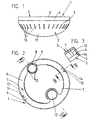
- the metering memory as a whole is with the reference numeral 1 denotes. It has a bowl-like shape designed metering storage lower part 2, at the Shell edge 3 of the inward edge 4 of a metering storage lid 5 is present. The top of the lid 6 forms a central indentation 7 which extends to the edge of the shell 3 is enough.
- the metering 1 is form and heat-stable plastic material used.
- the dosing reservoir cover 5 is on the lower portion of the dosing reservoir 2 hinged.
- the lower part of the dosing reservoir forms 2 a hollow, integrally molded material designed pivot pin 8 from.
- This tower over the Shell edge 3 and forms a circumferential, with Collars equipped with bevels 9.
- slits 10 extending from the collar 9 allow inward suspension of the collar 9 when Put on the dosing reservoir cover 5 in the way of Plug-in / snap-in connection.
- the confiscation 7 forms a Push-through opening 11, which corresponds to the diameter of the pivot pin 8 is adjusted.
- the collar 9 engages behind the push-through opening 11 and is based on the top of the confiscation 7 and thus irreversibly holds the dosing reservoir cover 5, so that only a pivoting of the dosing reservoir cover 5 around the pivot pin 8 is made possible.
- the articulation axis formed by this extends decentralized and parallel to the longitudinal axis of the dosing reservoir 1.
- the lid top 6 Shaped in diametrical opposite position to the pivot pin 8 the lid top 6 an inward actuating trough 12 for attacking a finger of an operating hand, around the dosing reservoir cover 5, for example to pivot into the position shown in Figure 5. Regardless the swivel direction overflows one provided on the lid edge 4 Latch 13 the shell edge 3.
- the locking lug 13 forms Height of the division joint T a roof-shaped apex 14, that both when opening and when closing the dosing reservoir lid 5 overflows the bowl edge 3.
- the lower part of the dosing reservoir forms on the upper edge 3 of the shell 2 storage openings 15 from. These are slit-like designed, radially aligned and in even Circumferential distribution arranged on the edge 3 of the shell.
- the dosing storage lower part 2 has a central Receiving chamber A, which in the exemplary embodiment in particular to insert a dash-dot illustrated Detergent tablet 16 is used.
- a flow path connection given in the form of two spirals one inside the other trained channels K 1 and K 2. These are designed through two starting from the shell bottom 17, parallel to the longitudinal axis of the dosing reservoir Guide walls 18, 19, which at the level of the division T end up.
- Each spiral guide wall 18, 19 extends over an angle of approximately 450 ° such that the Flow path connection to receiving chamber A continuously tapered.
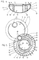
- FIG. 5 shows that the memory openings 15 assigned opening cross section 21, 21 'of Flow path connection or the channels K1, K2 is larger than the opening cross section assigned to the receiving chamber A. 20, 20 'of the flow path connection.
- the gap width is inner opening cross sections 20, 20 'smaller than one Tenths of the diameter of the receiving chamber A.
- FIG. 4 shows that the lower part of the metering reservoir 2 forms the channel floor and by means of the guide walls 18, 19 forms channel side walls.
- the dosing reservoir cover 5 represents a duct ceiling. Also is through the lower part of the dosing reservoir 2 or its Shell bottom 17 of the chamber bottom is formed. The one from this outgoing chamber side walls are part of the guide walls 18, 19.
- the dosing reservoir lid 5 represents the chamber ceiling.
- Channels K1, K2 run peripherally to the middle receiving chamber A of the dosing tank.
- Receiving chamber A For filling those located in the lower part 2 of the metering reservoir Receiving chamber A is the metering reservoir cover 5 overcoming the rest in the illustrated in Figure 5 Swivel position. After that is the reception chamber A accessible. In this can in the embodiment a detergent tablet 16 can be inserted. Subsequently is the dosing reservoir cover 5 in the locked Bring closed position. The dosing memory is then add to the laundry. The washing liquid occurs through the storage openings 15 of the shell edge 3 and enters through the opening cross sections 21, 21 ' the spiral channels K1, K2 which connect the flow path to the reception chamber.
- this is also two-part dosing reservoir designated by the number 22. It is composed of a truncated cone Dosing storage lower part 23 and a closing this Dosing reservoir cover 24.
- the dosing reservoir cover 24 is screw-connected to the lower part of the metering reservoir 23, for which purpose the lower part 23 of the metering reservoir is eccentric extending screw socket 25 forms. Outside is the screw socket 25 with an external thread 26 Mistake. This is in engagement with the internal thread a screw socket 28 protruding into the lid, which due to the eccentricity of this screw socket 28 over a partial area in the lid edge 29 transforms.
- the screw socket 28 forms a side wall of two symmetrically arranged to each other Channels K3, K4.
- These side walls 32, 33 act both as inner and also as the outer side wall of a channel section of the Channels K3, K4 representing flow path connections.
- the two side walls 32, 33 remain between them an average flow cross section 35. This is larger than the flow cross section assigned to the receiving chamber A ' 36, 37. Furthermore, it is larger than that Associated storage openings 38 of the metering storage lid 24 Flow cross section 38, 39.
- the flow gap forming the flow cross-section 35 in the screw cap 28 a passage opening 41 associated with the outflow of the washing liquid favored from the opening cross sections 31, 31 '.
- the lower part of the dosing reservoir forms on the jacket wall 42 is approximately over 180 ° extending recessed grip 43. This is in Coverage area with the crescent-shaped Chamber cover 30.
- the above-described metering reservoir 22 can be unscrewed of the dosing reservoir cover 24 conveniently through the large opening, formed by the screw socket 25 fill. Thereafter, the metering reservoir cover 24 is in the way the screw connection. Then the Filled dosing reservoir in the washing drum Laundry can be added.
- the washing liquid passes through the storage openings 38 of the metering storage cover 24 in the channels K3, K4, which the flow path connections form to the receiving chamber A '. Because of the changing flow cross-sections of the channels K3, K4 also find a change in flow behavior instead, so that the detergent particles coming from the opening cross sections 31, 31 ' with certainty and in this form the storage openings 38 leave. A selective bleaching of the laundry is therefore effective prevented.
Landscapes
- Textile Engineering (AREA)
- Engineering & Computer Science (AREA)
- Washing And Drying Of Tableware (AREA)
- External Artificial Organs (AREA)
- Closures For Containers (AREA)
- Feeding, Discharge, Calcimining, Fusing, And Gas-Generation Devices (AREA)
- Medicines Containing Plant Substances (AREA)
- Soy Sauces And Products Related Thereto (AREA)
- Containers And Packaging Bodies Having A Special Means To Remove Contents (AREA)
- Electrotherapy Devices (AREA)
- Medicines Containing Material From Animals Or Micro-Organisms (AREA)
- Input Circuits Of Receivers And Coupling Of Receivers And Audio Equipment (AREA)
- Treatment Of Fiber Materials (AREA)
- Detergent Compositions (AREA)
Description

- Figur 1
- eine Ansicht des Dosierspeichers gemäß der ersten Ausführungsform bei in Verschlußstellung befindlichem Dosierspeicherdeckel,
- Figur 2
- eine Draufsicht auf den Dosierspeicher,
- Figur 3
- in vergrößerter Darstellung den Schnitt nach der Linie III-III in Figur 2,
- Figur 4
- den Schnitt nach der Linie IV-IV in Figur 2,
- Figur 5
- eine Draufsicht auf den Dosierspeicher bei in die Offenstellung geschwenktem Dosierspeicherdeckel,
- Figur 6
- eine Ansicht des Dosierspeichers gemäß der zweiten Ausführungsform bei in Verschlußstellung befindlichem Dosierspeicherdeckel,
- Figur 7
- eine der Figur 6 entsprechende Darstellung, wobei der Dosierspeicherdeckel abgeschraubt ist,
- Figur 8
- einen Längsschnitt durch den geschlossenen Dosierspeicher,
- Figur 9
- eine Draufsicht auf das Dosierspeicherunterteil mit Blick in die Aufnahmekammer und
- Figur 10
- den Schnitt nach der Linie X-X in Figur 8.
Claims (27)
- Dosierspeicher (1) zur Aufnahme und Abgabe eines Wäschebehandlungsmittels, insbesondere in fester, gelartiger oder pastenartiger Form, mit einer Aufnahmekammer (A,A') für das Wäschebehandlungsmittel und Öffnungen (15, 38) zum Eintritt/Austritt der Waschflüssigkeit aus dem Dosierspeicher (1), wobei eine Strömungswegverbindung für die Waschflüssigkeit zwischen den Öffnungen (15, 38) und der Aufnahmekammer (A,A') ausgebildet ist und wobei der Dosierspeicher im wesentlichen aus einem formstabilen Kunststoffmaterial besteht,
dadurch gekennzeichnet,
daß die von der Waschflüssigkeit durchströmbare Strömungswegverbindung durch mindestens eine Führungswand (18, 19, 32, 33) als die direkte Strömungswegverbindung zwischen der Aufnahmekammer (A,A') und den Öffnungen (15, 38) kanalartig verlängernde Umwegstrecke ausgebildet ist. - Dosierspeicher nach Anspruch 1, dadurch gekennzeichnet, daß die Strömungswegverbindung ein spiralförmiger Kanal (K1, K2, K3, K4) ist.
- Dosierspeicher nach Anspruch 1, dadurch gekennzeichnet, daß die Strömungswegverbindung mäanderförmig gestaltet ist.
- Dosierspeicher nach Anspruch 1, dadurch gekennzeichnet, daß die Strömungswegverbindung labyrinthartig gestaltet ist.
- Dosierspeicher nach einem der vorhergehenden Ansprüche, dadurch gekennzeichnet, daß der Dosierspeicher (1) derart zweiteilig gestaltet ist, daß ein Dosierspeicherunterteil (2) einen Kanalboden und Kanalseitenwände (Führungswände (18, 19)) ausbildet und daß der Dosierspeicherdeckel (5) eine Kanaldecke darstellt.
- Dosierspeicher nach einem der vorhergehenden Ansprüche, dadurch gekennzeichnet, daß das Dosierspeicherunterteil (2) einen Kammerboden und Kammerseitenwände (Führungswände (18, 19) ausbildet und daß der Dosierspeicherdeckel (5) eine Kammerdecke darstellt.
- Dosierspeicher nach einem der vorhergehenden Ansprüche, dadurch gekennzeichnet, daß die Strömungswegverbindung peripher zu einer mittleren Aufnahmekammer (A) des Dosierspeichers (1) angeordnet ist.
- Dosierspeicher nach einem der vorhergehenden Ansprüche, dadurch gekennzeichnet, daß der Dosierspeicherdeckel (5) an dem Dosierspeicherunterteil (2) angelenkt ist derart, daß die Anlenkachse (8) dezentral und parallelachsig zur Längsachse des Dosierspeichers (1) verläuft.
- Dosierspeicher nach einem der vorhergehenden Ansprüche, dadurch gekennzeichnet, daß das Dosierspeicherunterteil (2) schalenartig gestaltet ist.
- Dosierspeicher nach einem der vorhergehenden Ansprüche, dadurch gekennzeichnet, daß die Speicheröffnungen (15) an einem oberen Schalenrand (3) angeordnet sind.
- Dosierspeicher nach Anspruch 10, gekennzeichnet durch im wesentlichen in gleichmäßiger Umfangsverteilung angeordnete, schlitzartige, radial ausgerichtete Speicheröffnungen (15).
- Dosierspeicher nach einem der vorhergehenden Ansprüche, dadurch gekennzeichnet, daß ein den Speicheröffnungen (15) zugeordneter Öffnungsquerschnitt (21, 21') der Strömungswegverbindung größer ist als ein der Aufnahmekammer (A) zugeordneter Öffnungsquerschnitt (20, 20') der Strömungswegverbindung.
- Dosierspeicher nach einem der vorhergehenden Ansprüche, dadurch gekennzeichnet, daß die Strömungswegverbindung zur Aufnahmekammer (A) hin kontinuierlich sich verjüngend ausgebildet ist.
- Dosierspeicher nach einem der vorhergehenden Ansprüche, gekennzeichnet durch zwei ineinander spiralförmig ausgebildete Kanäle (K1, K2).
- Dosierspeicher nach einem der vorhergehenden Ansprüche, dadurch gekennzeichnet, daß die inneren und äußeren Öffnungsquerschnitte (20, 20' bzw. 21, 21') der Kanäle (K1, K2) jeweils um ca. 180° zueinander versetzt sind.
- Dosierspeicher nach einem der vorhergehenden Ansprüche, dadurch gekennzeichnet, daß der innere und äußere Öffnungsquerschnitt (20, 21 bzw. 20', 21') eines Kanals (K1 bzw. K2) um ca. 90° versetzt zueinander angeordnet sind.
- Dosierspeicher nach einem der vorhergehenden Ansprüche, gekennzeichnet durch eine in diametraler Gegenüberlage zum Anlenkzapfen (8) an der Deckeloberseite (6) ausgeformte Betätigungsmulde (12).
- Dosierspeicher nach einem der vorhergehenden Ansprüche, gekennzeichnet durch eine Steck/Rastverbindung der Deckel-Gelenkachse (8).
- Dosierspeicher nach einem der vorhergehenden Ansprüche, dadurch gekennzeichnet, daß die Strömungswegverbindung im Dosierspeicherdeckel (24) und die Aufnahmekammer (A') im Dosierspeicherunterteil (23) ausgebildet sind.
- Dosierspeicher nach einem der vorhergehenden Ansprüche, dadurch gekennzeichnet, daß der Dosierspeicherdeckel (24) mit dem Dosierspeicherunterteil (23) schraubverbunden ist, wobei das Dosierspeicherunterteil (23) einen exzentrisch verlaufenden Schraubstutzen (25) ausbildet.
- Dosierspeicher nach einem der vorhergehenden Ansprüche, dadurch gekennzeichnet, daß die der Aufnahmekammer (A') zugeordneten Öffnungsquerschnitte (36, 37) der Strömungswegverbindung in einer Seitenwand eines Kanals (K3, K4) ausgebildet sind.
- Dosierspeicher nach Anspruch 20 oder 21, dadurch gekennzeichnet, daß die Seitenwand von dem Deckel-Schraubstutzen (28) gebildet ist.
- Dosierspeicher nach einem der Ansprüche 20-22, dadurch gekennzeichnet, daß zwischen Deckel-Schraubstutzen (28) und Deckelaußenwandung (Deckelrand 29) eine spiralabschnittsförmig verlaufende Führungswand (32, 33) vorgesehen ist, welche sowohl als innere als auch als äußere Seitenwand eines Kanalabschnittes der Strömungswegverbindung wirkt.
- Dosierspeicher nach einem der vorhergehenden Ansprüche, dadurch gekennzeichnet, daß ein mittlerer Durchströmquerschnitt (35) der Strömungswegverbindung größer ist als ein der Aufnahmekammer (A') zugeordneter Strömungsquerschnitt (36, 37) und ein den Speicheröffnungen (38) zugeordneter Strömungsquerschnitt (39, 40).
- Dosierspeicher nach einem der vorhergehenden Ansprüche, gekennzeichnet durch zwei symmetrisch zueinander angeordnete, spriralabschnittsförmig gestaltete Führungswände (32, 33), die zwischen sich einen Durchströmspalt (Durchströmquerschnitt 35) belassen.
- Dosierspeicher nach einem der vorhergehenden Ansprüche, dadurch gekennzeichnet, daß zugeordnet zu dem Durchströmspalt (35) im Deckel-Schraubstutzen (28) eine Durchtrittsöffnung (41) vorgesehen ist.
- Dosierspeicher nach einem der vorhergehenden Ansprüche, gekennzeichnet durch eine von der Mantelwand (42) des Dosierspeicherunterteils (23) gestaltete, sich etwa über 180° erstreckende Griffmulde (43).
Applications Claiming Priority (3)
| Application Number | Priority Date | Filing Date | Title |
|---|---|---|---|
| DE4421317 | 1994-06-17 | ||
| DE4421317A DE4421317C1 (de) | 1994-06-17 | 1994-06-17 | Dosierspeicher |
| PCT/EP1995/002258 WO1995035403A1 (de) | 1994-06-17 | 1995-06-12 | Dosierspeicher |
Publications (2)
| Publication Number | Publication Date |
|---|---|
| EP0765412A1 EP0765412A1 (de) | 1997-04-02 |
| EP0765412B1 true EP0765412B1 (de) | 2000-09-13 |
Family
ID=6520890
Family Applications (1)
| Application Number | Title | Priority Date | Filing Date |
|---|---|---|---|
| EP95923304A Expired - Lifetime EP0765412B1 (de) | 1994-06-17 | 1995-06-12 | Dosierspeicher |
Country Status (8)
| Country | Link |
|---|---|
| EP (1) | EP0765412B1 (de) |
| AT (1) | ATE196328T1 (de) |
| DE (2) | DE4421317C1 (de) |
| DK (1) | DK0765412T3 (de) |
| ES (1) | ES2150571T3 (de) |
| GR (1) | GR3034596T3 (de) |
| PT (1) | PT765412E (de) |
| WO (1) | WO1995035403A1 (de) |
Cited By (1)
| Publication number | Priority date | Publication date | Assignee | Title |
|---|---|---|---|---|
| DE10052861B4 (de) * | 2000-10-24 | 2004-10-07 | Ecolab Inc., St. Paul | Dosierspeicher für insbesondere pastenförmige Wäschebehandlungsmittel, Dosiervorrichtung zur Befüllung eines solchen Dosierspeichers und Dosiersystem aus einem solchen Dosierspeicher und einer passenden Dosiervorrichtung |
Families Citing this family (2)
| Publication number | Priority date | Publication date | Assignee | Title |
|---|---|---|---|---|
| DE19806113A1 (de) * | 1998-02-14 | 1999-08-19 | Henkel Ecolab Gmbh & Co Ohg | Verfahren zur Dosierung von Waschmitteln und dazu geeignete Vorrichtung |
| WO2012175284A1 (en) * | 2011-06-23 | 2012-12-27 | Unilever Plc | Dosing device for particulate laundry composition |
Family Cites Families (3)
| Publication number | Priority date | Publication date | Assignee | Title |
|---|---|---|---|---|
| US3400808A (en) * | 1966-03-01 | 1968-09-10 | Colgate Palmolive Co | Combination dispensing and measuring vessel |
| FR2628451B2 (fr) * | 1987-05-06 | 1991-08-30 | Procter & Gamble | Procede pour le lavage et l'adoucissement du linge en machine |
| DE3844368C1 (de) * | 1988-12-30 | 1990-04-12 | Henkel Kgaa, 4000 Duesseldorf, De |
-
1994
- 1994-06-17 DE DE4421317A patent/DE4421317C1/de not_active Expired - Fee Related
-
1995
- 1995-06-12 DK DK95923304T patent/DK0765412T3/da active
- 1995-06-12 AT AT95923304T patent/ATE196328T1/de not_active IP Right Cessation
- 1995-06-12 ES ES95923304T patent/ES2150571T3/es not_active Expired - Lifetime
- 1995-06-12 DE DE59508719T patent/DE59508719D1/de not_active Expired - Fee Related
- 1995-06-12 WO PCT/EP1995/002258 patent/WO1995035403A1/de not_active Ceased
- 1995-06-12 EP EP95923304A patent/EP0765412B1/de not_active Expired - Lifetime
- 1995-06-12 PT PT95923304T patent/PT765412E/pt unknown
-
2000
- 2000-10-11 GR GR20000402285T patent/GR3034596T3/el not_active IP Right Cessation
Cited By (1)
| Publication number | Priority date | Publication date | Assignee | Title |
|---|---|---|---|---|
| DE10052861B4 (de) * | 2000-10-24 | 2004-10-07 | Ecolab Inc., St. Paul | Dosierspeicher für insbesondere pastenförmige Wäschebehandlungsmittel, Dosiervorrichtung zur Befüllung eines solchen Dosierspeichers und Dosiersystem aus einem solchen Dosierspeicher und einer passenden Dosiervorrichtung |
Also Published As
| Publication number | Publication date |
|---|---|
| DE59508719D1 (de) | 2000-10-19 |
| ATE196328T1 (de) | 2000-09-15 |
| WO1995035403A1 (de) | 1995-12-28 |
| DK0765412T3 (da) | 2001-01-22 |
| DE4421317C1 (de) | 1996-02-29 |
| PT765412E (pt) | 2000-12-29 |
| EP0765412A1 (de) | 1997-04-02 |
| GR3034596T3 (en) | 2001-01-31 |
| ES2150571T3 (es) | 2000-12-01 |
Similar Documents
| Publication | Publication Date | Title |
|---|---|---|
| DE3729491C2 (de) | Abgabekopf zur Vermischung und Dosierung eines Zweikomponenten-Produkts und Verwendung des Abgabekopfes | |
| DE60101508T2 (de) | Einheit zum unmittelbaren Vermischen von zwei Produkten | |
| EP0157121B1 (de) | Behälter zum Ausbringen von Dentalmassen | |
| EP0103110B1 (de) | Beimischgerät | |
| DE2644786C3 (de) | Ausgabedüse, insbesondere für flüssige und halbflüssige Substanzen | |
| DE69205001T2 (de) | Dosiervorrichtung fur flussigkeiten. | |
| DE602005006092T2 (de) | Wäschetrockner mit Zusatzmittelabgabevorrichtung | |
| DE2622125C2 (de) | Nachfüllbehälter für pumpbare Waschmittel-Wirkstoffe | |
| DE2160447A1 (de) | Gerät zum Weichmachen von Wasser | |
| DE2639923C2 (de) | Waschmittelzugabevorrichtung | |
| DE3514132A1 (de) | Behaelterverschluss | |
| DE4008429A1 (de) | Dosiereinrichtung fuer ein wasseraktivierbares mittel | |
| DE4421317C1 (de) | Dosierspeicher | |
| DE29709383U1 (de) | Behälter für pastöse Massen | |
| EP0780508B1 (de) | Dosierspeicher | |
| DE3416008A1 (de) | Dosiergeraet | |
| DE19717029C1 (de) | Vorrichtung zur Aufnahme und dosierten Abgabe eines Wasch- oder Reinigungsmittels | |
| DE102016100293A1 (de) | WC-Wirkstoffhalter | |
| EP0793081A1 (de) | Flüssigkeitsbehälter mit Dosiervorrichtung | |
| EP2885088B1 (de) | Austragvorrichtung | |
| DE2126240A1 (de) | Vorrichtung zum Einführen der Reinigungsmittel in eine Waschmaschine | |
| DE69407641T2 (de) | Dosiervorrichtung, insbesondere für viskose Produkte | |
| DE19547639C1 (de) | Dosierspeicher | |
| DE3214056C2 (de) | Statischer Mischer für flüssige und/oder pastöse Komponenten | |
| CH656984A5 (de) | Geraetestecker. |
Legal Events
| Date | Code | Title | Description |
|---|---|---|---|
| PUAI | Public reference made under article 153(3) epc to a published international application that has entered the european phase |
Free format text: ORIGINAL CODE: 0009012 |
|
| 17P | Request for examination filed |
Effective date: 19961209 |
|
| AK | Designated contracting states |
Kind code of ref document: A1 Designated state(s): AT BE CH DE DK ES FR GB GR IE IT LI NL PT SE |
|
| 17Q | First examination report despatched |
Effective date: 19990216 |
|
| GRAG | Despatch of communication of intention to grant |
Free format text: ORIGINAL CODE: EPIDOS AGRA |
|
| GRAG | Despatch of communication of intention to grant |
Free format text: ORIGINAL CODE: EPIDOS AGRA |
|
| GRAH | Despatch of communication of intention to grant a patent |
Free format text: ORIGINAL CODE: EPIDOS IGRA |
|
| GRAH | Despatch of communication of intention to grant a patent |
Free format text: ORIGINAL CODE: EPIDOS IGRA |
|
| GRAA | (expected) grant |
Free format text: ORIGINAL CODE: 0009210 |
|
| AK | Designated contracting states |
Kind code of ref document: B1 Designated state(s): AT BE CH DE DK ES FR GB GR IE IT LI NL PT SE |
|
| REF | Corresponds to: |
Ref document number: 196328 Country of ref document: AT Date of ref document: 20000915 Kind code of ref document: T |
|
| REG | Reference to a national code |
Ref country code: CH Ref legal event code: EP |
|
| REF | Corresponds to: |
Ref document number: 59508719 Country of ref document: DE Date of ref document: 20001019 |
|
| REG | Reference to a national code |
Ref country code: IE Ref legal event code: FG4D Free format text: GERMAN |
|
| ET | Fr: translation filed | ||
| ITF | It: translation for a ep patent filed | ||
| REG | Reference to a national code |
Ref country code: ES Ref legal event code: FG2A Ref document number: 2150571 Country of ref document: ES Kind code of ref document: T3 |
|
| REG | Reference to a national code |
Ref country code: PT Ref legal event code: SC4A Free format text: AVAILABILITY OF NATIONAL TRANSLATION Effective date: 20000913 |
|
| REG | Reference to a national code |
Ref country code: DK Ref legal event code: T3 |
|
| GBT | Gb: translation of ep patent filed (gb section 77(6)(a)/1977) |
Effective date: 20010111 |
|
| PGFP | Annual fee paid to national office [announced via postgrant information from national office to epo] |
Ref country code: DK Payment date: 20010613 Year of fee payment: 7 |
|
| PGFP | Annual fee paid to national office [announced via postgrant information from national office to epo] |
Ref country code: CH Payment date: 20010615 Year of fee payment: 7 |
|
| PGFP | Annual fee paid to national office [announced via postgrant information from national office to epo] |
Ref country code: IE Payment date: 20010622 Year of fee payment: 7 |
|
| PGFP | Annual fee paid to national office [announced via postgrant information from national office to epo] |
Ref country code: GR Payment date: 20010627 Year of fee payment: 7 |
|
| PLBE | No opposition filed within time limit |
Free format text: ORIGINAL CODE: 0009261 |
|
| STAA | Information on the status of an ep patent application or granted ep patent |
Free format text: STATUS: NO OPPOSITION FILED WITHIN TIME LIMIT |
|
| 26N | No opposition filed | ||
| REG | Reference to a national code |
Ref country code: GB Ref legal event code: IF02 |
|
| PG25 | Lapsed in a contracting state [announced via postgrant information from national office to epo] |
Ref country code: IE Free format text: LAPSE BECAUSE OF NON-PAYMENT OF DUE FEES Effective date: 20020612 |
|
| PG25 | Lapsed in a contracting state [announced via postgrant information from national office to epo] |
Ref country code: LI Free format text: LAPSE BECAUSE OF NON-PAYMENT OF DUE FEES Effective date: 20020630 Ref country code: CH Free format text: LAPSE BECAUSE OF NON-PAYMENT OF DUE FEES Effective date: 20020630 |
|
| PG25 | Lapsed in a contracting state [announced via postgrant information from national office to epo] |
Ref country code: DK Free format text: LAPSE BECAUSE OF NON-PAYMENT OF DUE FEES Effective date: 20020731 |
|
| PG25 | Lapsed in a contracting state [announced via postgrant information from national office to epo] |
Ref country code: GR Free format text: LAPSE BECAUSE OF NON-PAYMENT OF DUE FEES Effective date: 20021231 |
|
| REG | Reference to a national code |
Ref country code: DK Ref legal event code: EBP |
|
| REG | Reference to a national code |
Ref country code: CH Ref legal event code: PL |
|
| REG | Reference to a national code |
Ref country code: IE Ref legal event code: MM4A |
|
| PGFP | Annual fee paid to national office [announced via postgrant information from national office to epo] |
Ref country code: NL Payment date: 20070603 Year of fee payment: 13 |
|
| PGFP | Annual fee paid to national office [announced via postgrant information from national office to epo] |
Ref country code: SE Payment date: 20070607 Year of fee payment: 13 Ref country code: DE Payment date: 20070607 Year of fee payment: 13 |
|
| PGFP | Annual fee paid to national office [announced via postgrant information from national office to epo] |
Ref country code: PT Payment date: 20070612 Year of fee payment: 13 |
|
| PGFP | Annual fee paid to national office [announced via postgrant information from national office to epo] |
Ref country code: AT Payment date: 20070614 Year of fee payment: 13 |
|
| PGFP | Annual fee paid to national office [announced via postgrant information from national office to epo] |
Ref country code: ES Payment date: 20070717 Year of fee payment: 13 |
|
| PGFP | Annual fee paid to national office [announced via postgrant information from national office to epo] |
Ref country code: GB Payment date: 20070606 Year of fee payment: 13 |
|
| PGFP | Annual fee paid to national office [announced via postgrant information from national office to epo] |
Ref country code: IT Payment date: 20070616 Year of fee payment: 13 |
|
| PGFP | Annual fee paid to national office [announced via postgrant information from national office to epo] |
Ref country code: BE Payment date: 20070821 Year of fee payment: 13 |
|
| PGFP | Annual fee paid to national office [announced via postgrant information from national office to epo] |
Ref country code: FR Payment date: 20070608 Year of fee payment: 13 |
|
| REG | Reference to a national code |
Ref country code: PT Ref legal event code: MM4A Free format text: LAPSE DUE TO NON-PAYMENT OF FEES Effective date: 20081212 |
|
| BERE | Be: lapsed |
Owner name: *HENKEL K.G.A.A. Effective date: 20080630 |
|
| PG25 | Lapsed in a contracting state [announced via postgrant information from national office to epo] |
Ref country code: PT Free format text: LAPSE BECAUSE OF NON-PAYMENT OF DUE FEES Effective date: 20081212 |
|
| EUG | Se: european patent has lapsed | ||
| GBPC | Gb: european patent ceased through non-payment of renewal fee |
Effective date: 20080612 |
|
| NLV4 | Nl: lapsed or anulled due to non-payment of the annual fee |
Effective date: 20090101 |
|
| PG25 | Lapsed in a contracting state [announced via postgrant information from national office to epo] |
Ref country code: BE Free format text: LAPSE BECAUSE OF NON-PAYMENT OF DUE FEES Effective date: 20080630 |
|
| REG | Reference to a national code |
Ref country code: FR Ref legal event code: ST Effective date: 20090228 |
|
| PG25 | Lapsed in a contracting state [announced via postgrant information from national office to epo] |
Ref country code: DE Free format text: LAPSE BECAUSE OF NON-PAYMENT OF DUE FEES Effective date: 20090101 Ref country code: AT Free format text: LAPSE BECAUSE OF NON-PAYMENT OF DUE FEES Effective date: 20080612 |
|
| PG25 | Lapsed in a contracting state [announced via postgrant information from national office to epo] |
Ref country code: NL Free format text: LAPSE BECAUSE OF NON-PAYMENT OF DUE FEES Effective date: 20090101 |
|
| PG25 | Lapsed in a contracting state [announced via postgrant information from national office to epo] |
Ref country code: GB Free format text: LAPSE BECAUSE OF NON-PAYMENT OF DUE FEES Effective date: 20080612 |
|
| REG | Reference to a national code |
Ref country code: ES Ref legal event code: FD2A Effective date: 20080613 |
|
| PG25 | Lapsed in a contracting state [announced via postgrant information from national office to epo] |
Ref country code: IT Free format text: LAPSE BECAUSE OF NON-PAYMENT OF DUE FEES Effective date: 20080612 Ref country code: FR Free format text: LAPSE BECAUSE OF NON-PAYMENT OF DUE FEES Effective date: 20080630 |
|
| PG25 | Lapsed in a contracting state [announced via postgrant information from national office to epo] |
Ref country code: ES Free format text: LAPSE BECAUSE OF NON-PAYMENT OF DUE FEES Effective date: 20080613 |
|
| PG25 | Lapsed in a contracting state [announced via postgrant information from national office to epo] |
Ref country code: SE Free format text: LAPSE BECAUSE OF NON-PAYMENT OF DUE FEES Effective date: 20080613 |