EP0765211B1 - Verfahren und vorrichtung zum nachformen eines extrudierten und auf ein objekt aufgebrachten profilstranges - Google Patents
Verfahren und vorrichtung zum nachformen eines extrudierten und auf ein objekt aufgebrachten profilstranges Download PDFInfo
- Publication number
- EP0765211B1 EP0765211B1 EP95923408A EP95923408A EP0765211B1 EP 0765211 B1 EP0765211 B1 EP 0765211B1 EP 95923408 A EP95923408 A EP 95923408A EP 95923408 A EP95923408 A EP 95923408A EP 0765211 B1 EP0765211 B1 EP 0765211B1
- Authority
- EP
- European Patent Office
- Prior art keywords
- pressing member
- movement
- punch
- groove
- bead
- Prior art date
- Legal status (The legal status is an assumption and is not a legal conclusion. Google has not performed a legal analysis and makes no representation as to the accuracy of the status listed.)
- Expired - Lifetime
Links
Images


Classifications
-
- B—PERFORMING OPERATIONS; TRANSPORTING
- B29—WORKING OF PLASTICS; WORKING OF SUBSTANCES IN A PLASTIC STATE IN GENERAL
- B29C—SHAPING OR JOINING OF PLASTICS; SHAPING OF MATERIAL IN A PLASTIC STATE, NOT OTHERWISE PROVIDED FOR; AFTER-TREATMENT OF THE SHAPED PRODUCTS, e.g. REPAIRING
- B29C43/00—Compression moulding, i.e. applying external pressure to flow the moulding material; Apparatus therefor
- B29C43/32—Component parts, details or accessories; Auxiliary operations
- B29C43/36—Moulds for making articles of definite length, i.e. discrete articles
- B29C43/42—Moulds for making articles of definite length, i.e. discrete articles for undercut articles
-
- B—PERFORMING OPERATIONS; TRANSPORTING
- B29—WORKING OF PLASTICS; WORKING OF SUBSTANCES IN A PLASTIC STATE IN GENERAL
- B29C—SHAPING OR JOINING OF PLASTICS; SHAPING OF MATERIAL IN A PLASTIC STATE, NOT OTHERWISE PROVIDED FOR; AFTER-TREATMENT OF THE SHAPED PRODUCTS, e.g. REPAIRING
- B29C70/00—Shaping composites, i.e. plastics material comprising reinforcements, fillers or preformed parts, e.g. inserts
- B29C70/68—Shaping composites, i.e. plastics material comprising reinforcements, fillers or preformed parts, e.g. inserts by incorporating or moulding on preformed parts, e.g. inserts or layers, e.g. foam blocks
- B29C70/74—Moulding material on a relatively small portion of the preformed part, e.g. outsert moulding
- B29C70/76—Moulding on edges or extremities of the preformed part
- B29C70/763—Moulding on edges or extremities of the preformed part the edges being disposed in a substantial flat plane
-
- B—PERFORMING OPERATIONS; TRANSPORTING
- B29—WORKING OF PLASTICS; WORKING OF SUBSTANCES IN A PLASTIC STATE IN GENERAL
- B29C—SHAPING OR JOINING OF PLASTICS; SHAPING OF MATERIAL IN A PLASTIC STATE, NOT OTHERWISE PROVIDED FOR; AFTER-TREATMENT OF THE SHAPED PRODUCTS, e.g. REPAIRING
- B29C43/00—Compression moulding, i.e. applying external pressure to flow the moulding material; Apparatus therefor
- B29C43/02—Compression moulding, i.e. applying external pressure to flow the moulding material; Apparatus therefor of articles of definite length, i.e. discrete articles
- B29C43/18—Compression moulding, i.e. applying external pressure to flow the moulding material; Apparatus therefor of articles of definite length, i.e. discrete articles incorporating preformed parts or layers, e.g. compression moulding around inserts or for coating articles
-
- B—PERFORMING OPERATIONS; TRANSPORTING
- B29—WORKING OF PLASTICS; WORKING OF SUBSTANCES IN A PLASTIC STATE IN GENERAL
- B29C—SHAPING OR JOINING OF PLASTICS; SHAPING OF MATERIAL IN A PLASTIC STATE, NOT OTHERWISE PROVIDED FOR; AFTER-TREATMENT OF THE SHAPED PRODUCTS, e.g. REPAIRING
- B29C43/00—Compression moulding, i.e. applying external pressure to flow the moulding material; Apparatus therefor
- B29C43/32—Component parts, details or accessories; Auxiliary operations
- B29C43/36—Moulds for making articles of definite length, i.e. discrete articles
- B29C43/3697—Moulds for making articles of definite length, i.e. discrete articles comprising rollers or belts cooperating with non-rotating mould parts
-
- B—PERFORMING OPERATIONS; TRANSPORTING
- B29—WORKING OF PLASTICS; WORKING OF SUBSTANCES IN A PLASTIC STATE IN GENERAL
- B29L—INDEXING SCHEME ASSOCIATED WITH SUBCLASS B29C, RELATING TO PARTICULAR ARTICLES
- B29L2031/00—Other particular articles
- B29L2031/26—Sealing devices, e.g. packaging for pistons or pipe joints
-
- B—PERFORMING OPERATIONS; TRANSPORTING
- B29—WORKING OF PLASTICS; WORKING OF SUBSTANCES IN A PLASTIC STATE IN GENERAL
- B29L—INDEXING SCHEME ASSOCIATED WITH SUBCLASS B29C, RELATING TO PARTICULAR ARTICLES
- B29L2031/00—Other particular articles
- B29L2031/778—Windows
- B29L2031/7782—Glazing
-
- Y—GENERAL TAGGING OF NEW TECHNOLOGICAL DEVELOPMENTS; GENERAL TAGGING OF CROSS-SECTIONAL TECHNOLOGIES SPANNING OVER SEVERAL SECTIONS OF THE IPC; TECHNICAL SUBJECTS COVERED BY FORMER USPC CROSS-REFERENCE ART COLLECTIONS [XRACs] AND DIGESTS
- Y10—TECHNICAL SUBJECTS COVERED BY FORMER USPC
- Y10T—TECHNICAL SUBJECTS COVERED BY FORMER US CLASSIFICATION
- Y10T428/00—Stock material or miscellaneous articles
- Y10T428/23—Sheet including cover or casing
- Y10T428/239—Complete cover or casing
-
- Y—GENERAL TAGGING OF NEW TECHNOLOGICAL DEVELOPMENTS; GENERAL TAGGING OF CROSS-SECTIONAL TECHNOLOGIES SPANNING OVER SEVERAL SECTIONS OF THE IPC; TECHNICAL SUBJECTS COVERED BY FORMER USPC CROSS-REFERENCE ART COLLECTIONS [XRACs] AND DIGESTS
- Y10—TECHNICAL SUBJECTS COVERED BY FORMER USPC
- Y10T—TECHNICAL SUBJECTS COVERED BY FORMER US CLASSIFICATION
- Y10T428/00—Stock material or miscellaneous articles
- Y10T428/24—Structurally defined web or sheet [e.g., overall dimension, etc.]
- Y10T428/2419—Fold at edge
- Y10T428/24198—Channel-shaped edge component [e.g., binding, etc.]
-
- Y—GENERAL TAGGING OF NEW TECHNOLOGICAL DEVELOPMENTS; GENERAL TAGGING OF CROSS-SECTIONAL TECHNOLOGIES SPANNING OVER SEVERAL SECTIONS OF THE IPC; TECHNICAL SUBJECTS COVERED BY FORMER USPC CROSS-REFERENCE ART COLLECTIONS [XRACs] AND DIGESTS
- Y10—TECHNICAL SUBJECTS COVERED BY FORMER USPC
- Y10T—TECHNICAL SUBJECTS COVERED BY FORMER US CLASSIFICATION
- Y10T428/00—Stock material or miscellaneous articles
- Y10T428/24—Structurally defined web or sheet [e.g., overall dimension, etc.]
- Y10T428/24777—Edge feature
Definitions
- the present invention relates to a method of postforming the zone transition between the initial part and the terminal part of an extruded profile made of a polymer, forming a closed frame, applied to the surface of a object and having a groove. In this process, a punch whose shape corresponds to the desired section of the profile is lowered onto the latter in swivel.
- the invention further relates to a device suitable for placing process work.
- EP-A-524 060 it is removed also a section of the profile by mechanical means after its hardening.
- a calibrated mold is then placed at this location covering the two contiguous ends of the frame profile and injecting and a polymer hardens relatively quickly in the mold complete the profiled frame.
- a tool known from EP-B-421 833 is consists of a lower plate in which is formed a cavity of molding and which can be in one or two pieces. The upper tray of compression is lowered onto the lower molding plate where it forms the streamlined.
- a process of this type well known and described in DE 90 115 73 U1, used for postforming a profiled bead, consisting of a reactive system based polyurethane, and extruded and applied to glazing.
- the mold consists of a device with two jaws, which is guided open position from the outside above the peripheral part of the glazing, fitted with profiled cord.
- the pivot axis of the two jaws is arranged outside the object.
- the invention sets itself the task of designing a process for postforming the transition zone of an extruded frame on an object that can serve in very diverse cases and which is also suitable for postforming profiled sections with undercuts or grooves anchor.
- the method of the invention is characterized in that a pressing member upper roller-shaped, in the cylindrical surface of which is formed a mold is led on the transition zone to postform by rotation around from the cylinder axis and by translation parallel to the surface of the object and perpendicular to the direction of the bead.
- the movements of rotation and translation are combined so that the pressing member unrolls its surface on the cord without sliding relative to it.
- the problem of the invention is to find a method for conforming a malleable material deposited on the surface of an object to obtain a cord with a rectilinear groove which has a undercut or anchor grooves.
- the process of the invention is characterized because it introduces into the material then we extract a punch in the shape of a profile whose section is locally narrower than the throat and which is animated by movements of rotation and translation perpendicular to its direction, preferably, the first movement is a translational movement towards the surface of the object and it is followed by a movement of rotation and simultaneously of translation parallel to the surface.
- the second rotational movement and that of translation parallel to the surface are adjusted one over the other so that the movement of the punch is carried out without sliding at the bottom of the throat.
- the punch is part of a cylindrical roller which wheel without sliding relative to the surface of the object.
- the forming method according to the invention makes it possible to move selectively in a determined direction the surplus material necessarily surplus in the transition zone, i.e. in the direction of advance cylindrical roller, punch-shaped profile support. Regardless the amount of excess, it can expand unimpeded.
- the rotation of the roller causes the deformation to start very early, i.e. at a when the actual forming is not yet completed. This forming and this simultaneous deformation allow to obtain special effects additional.
- the rotation of the roller with its punch allows for the first time to postform sections with undercuts thanks to the shape and movements of the punch.
- roller movement, punch support may vary depending on shape profiled bead which must be postformed.
- the roller can be driven on the bead to be profiled by a pure unwinding, i.e. by a movement free of relative sliding movement between the surface of the mass to be postformed and the surface of the roller in contact with this one.
- a pure unwinding i.e. by a movement free of relative sliding movement between the surface of the mass to be postformed and the surface of the roller in contact with this one.
- it may then be suitable print an increased speed during the second phase of the postforming to prevent protrusions from the roll, essentially the punch, forming the recesses and the undercuts cause unwanted distortions of profit.
- the method according to the invention can be used to postform the systems most diverse polymers. If the benefited cord is extruded by a system reactive, it is obvious that postforming must take place immediately at the following extrusion, before the extruded bead begins to harden by polymerization reaction. This is the case for example in the system of moisture curing polyurethane widely used currently or in two-component polyurethane systems. In however, when extruding the profiled bead with a polymer thermoplastic, postforming need not take place immediately after extrusion: it can also be done at a later time any. In this case, it is enough to take care to bring the material to the state plastic by adequate heating of the mass to be postformed.
- Non-stick coatings are known and will be chosen according to the polymer used in each case especially for the profile to be extruded.
- the material constituting the object on which the looped bead must be applied by extrusion or the shape of this object is at the bottom without importance.
- this may be glazing, in particular glazing automobiles to which a sealing frame is applied by extrusion elastomer, the seal being able to exercise other functions such as for example the centering of the glazing in the bay. It does not matter whether the glazing is made of glass or of transparent plastic or that it is covered with a transparent enamel or opaque, a thin layer or a plastic film.
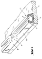
- Figure 1 shows in section a sheet glass 1 of this kind which is provided on the edge with a peripheral profile 2.
- the peripheral profile 2 consists of an extrudable elastomer and is applied by extrusion on the glass surface by means of an extrusion head relative movement with respect to the glazing and in particular driven by a robot at its periphery after a preliminary treatment of its surface.
- the profiled bead 2 is essentially U-shaped with a bottom 3 and two side walls 4 and 5.
- the interior surfaces opposite one to the other of the side walls 4 and 5 form with the bottom a groove 6 which widens down.
- the bonding bead is extruded in this groove 6.
- the profiled bead in the form of a frame 2 must have an end-to-end groove so that the mounting by gluing of a glass sheet like this is perfect.
- this continuous channel 6 it is not possible to obtain this continuous channel 6 by extrusion in the transition zone of the profile 2, i.e. at the location of the initial segment 9 and the final segment 10 of the extruded profile. Indeed, when we lay and lift the extruder die, irregular transition areas are formed at these locations and deformed 11, which must be postformed by an additional operating phase.
- the process of postforming this transient zone 11 on the surface glazing 1 whose profiled bead has the cross section shown in Figure 1 appears in detail in Figure 2.
- the lower mold 14 comprises a bearing surface 15 for the glass sheet 1 and a lateral surface 16 perpendicular to the first which serves to support the edge of the glazing 1.
- the upper end of the lateral surface 16 is arranged an edge cutting 17 which has the shape of a cutting edge and whose function will be explained further.
- the glass sheet is deposited 1 in the transition zone and it is pushed against the lateral surface 16 of the mold. The mass parts of polymer which extend beyond the edge of the sheet are thus limited laterally, so that the polymer bead 11 is ends flush with the song of the glass sheet.
- the upper pressing member 18 consists of a roller mounted in rotation whose pressing surface proper has the shape of a cylinder segment in the lateral surface of which the structure is provided pressing.
- the axis of rotation of this tool corresponds to the axis of the segment of cylinder.
- the shaft carrying the pressing member 18, which is not shown in the schematic sketch is mounted so that you can make a translational movement parallel to itself, i.e. remaining parallel at the edge of the window.
- the molding structure proper consists of a cavity 19 formed in the lateral surface which during rotation forms the lateral rib 5 of the profile, of a cavity 20 which forms the side and the top of the lateral rib 4 and a punch in the form of dovetail 21, which forms the groove 6 of the profile during the course of the pressure organ.
- the precise outline of the cavities 19 and 20 as well as the punch 21 depend on the section of the profiled bead that is desired in each case and its construction must be determined on a case-by-case basis.
- FIG. 2 represents various successive phases A to F of the rolling compression carried out using the tools described.
- the pressing member upper 18 is in such a position above the glass sheet 1 that the cutting edge (cutting edge) 23 formed by the outer surface cylindrical 22 of the upper pressing member and by the lateral surface of the cavity 19 is located exactly above the periphery of the side wall 5 of the cord.
- the upper compression tool lowers until the cutting edge 23 almost touches the surface of the glass.
- the excess polymer mass is pushed back from the transition 11, on the side facing the surface of the glass sheet, and repelled laterally.
- the remaining strip 26 thus formed is easy to remove then from the glass surface after hardening.
- the dovetail punch 21 penetrates in the polymer mass and begins to form the groove 6.
- the member 18 begins its rotation in the direction of the arrow G and its simultaneous translation in the direction of arrow H.
- phase D The rotation and the translation of the member 18 continue, so that the movement following phase D consists of a pure unfolding.
- the surface of the mold delimiting the cavity 20 also approaches of the cutting edge 17 which cuts off the excess polymer mass pushed outwards.
- the unwinding of the mold 18 continues again briefly which pulls the material of the wall 4 of the cavity a little upwards which becomes thinner when the punch 21, following the rotational movement and translation, turns up. In this movement, he respects the undercut of wall 4. This process continues until edge 24 delimiting upwards the punch 21 can be extracted upwards by rotation without deforming the internal surface of the side wall 5. At this time corresponds to phase E.
- phase F Translation of the pressing member is interrupted then while the rotation continues (phase F) until the punch 21 either completely extracted from the groove 6 by rotation.
- the slip that occurs then between the surface 25 delimiting the cavity 20 and the polymer mass excess 28 does not harm the profile.
- the organ of pressing 18 is raised.
- Postforming is completed and the glass sheet 1 is removed from the lower mold.
- the process of the invention is characterized in that that a roll-shaped upper pressing member in the surface cylindrical which is formed a mold is led on the transition zone to postform by rotation around the cylinder axis and by translation parallel to the surface of the object and perpendicular to the direction of the cord.
- the rotational and translational movements are combined so that the pressing member unrolls its surface on the bead without slip from it.
- This process also makes it possible to form U-shaped profiles including a wall side is provided with protruding anchor grooves on the side of the groove.
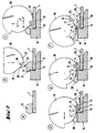
- An example of such an embodiment is shown again in Figure 3 by means of several consecutive phases of postforming.
- phase F comprises molding a profile 30 which, at the end of postforming, phase F, comprises a bottom 31, an inner side wall 32 provided with anchoring grooves 33 on the side of the groove, an outer side wall 34 and a lip 35 which laterally protrudes from the peripheral surface of the glass sheet in serving as a sealing and centering lip during and after assembly of the sheet of glass in the body of the automobile.
- the internal mold 38 is constituted as in the example described previously. Basically, the upper pressing member 40 also is built and installed as described in the previous example. However, at the difference from the previous example, the cutting edge 42 which limits the lip 35 towards the outside is arranged on the upper pressing member mounted in rotation.
- phase a) the glass sheet 50 is positioned on the lower mold with the mass of polymer forming the transition zone 51 and the tool is lowered onto the glass sheet.
- phase b) the unwinding of the pressing device in the direction arrows R and T, which form the grooves 33 on the inside of the wall 32 using the corresponding teeth of the punch 43.
- This course of the cylinder composed of the rotational movement R and the movement of translation T continues by preserving the two components of the movement during phases c, d and e which follow.
- the translational movement ensures whereas after the molding of the grooves 33 the punch 33 moves away from the wall without the grooves 33 being deformed by the rotation of the cylinder 40.
- the punch 43 is extracted from the groove of the profile.
- the outer wall 34 is molded and the cutting edge 42 cuts the excess mass of polymer while the lip is provided with a limit sharp.
- the mold is lifted. The 5O glass sheet with its postformed transition zone can be extracted from the lower mold.
- FIG. 4 A machine which makes it possible to carry out the process is shown in the Figure 4 with its essential characteristics.
- a frame 56 On the machine frame 55, on the one hand, a frame 56 is mounted vertically displaceable.
- the framework 56 is slidably mounted thanks to a system of rods and ball rings.
- the hydraulic brake 59 to which the frame 56 is connected by the bar 60 serves to dampen vertical movement.
- the vertical movement is controlled by the cylinder 62 which transmits the lifting movement through the piston rod 63 to the frame 56.
- a plate 66 carrying the lower part of the mold 65 is arranged in rotation about a pivot axis 67.
- the rotation of this plate 66 is effected by the jack 68 fixed on one side to the machine frame 55 by a pivot bearing 69 and on the other side at the plate 66 by a bearing 70.
- a shaft of horizontal guide 72 On the vertically movable frame 56 is disposed a shaft of horizontal guide 72 on which a movable carriage 74 is arranged so sliding.
- the damping and braking of the horizontal movement of the carriage 74 are provided by the hydraulic brake 76 which acts on carriage 74 by the piston rod 77.
- a rack 79 is fixed to the frame 56 with the teeth up.
- a second rack 79 is mounted so movable against the frame 56 with the teeth down.
- Rack 80 is actuated by the jack 82 whose piston rod 83 is connected to the rack 80.
- a horizontal shaft 85 is mounted on the carriage 74.
- the pressing member upper 86 proper and on the other hand a toothed wheel.
- the gear wheel is meshed with both the bottom rack and the rack upper 80.
- the lower rack should also be movably mounted and provided with its own drive.
- the rack 79 is also coupled with the piston rod of a jack 89 fixed to frame 56.
- the glass sheet 50 is deposited on the lower mold 65 and it is positioned.
- the frame 56 is then lowered by actuation of the jack 62 until the tool 86 almost touches the surface of the glass sheet 50.
- the molding of the tool 86 is carried out by actuation of the cylinder 82 and, if applicable, cylinder 89.
- the frame 56 is lifted by actuation of the cylinder 62.
- the control of the cylinder 68 of plate 66 prints a downward tilt away from the sheet of glass, outwards.
- the glass sheet 50 and the postformed profile 30 which can possibly adhere slightly to the mold 65 are thus detached from the mold 65. It is then easy to remove the glass sheet 50.
- the mold 65 can be provided with heating or cooling means, this which, depending on the extrusion material used, accelerates hardening by cooling or the reaction by heating the polymer.
Claims (12)
- Verfahren zum Formen eines auf der Oberfläche eines Gegenstandes (1) abgelegten verformbaren und härtbaren Materials zur Herstellung einer geradlinigen Hohlkehle (6) mit einem Hinterschnitt und/oder mit Verankerungsvorsprüngen, dadurch gekennzeichnet, daß eine Formleiste (21;43), deren Querschnitt örtlich schmäler ist als die Hohlkehle (6), in das Material eingeführt und wieder herausgezogen wird, und daß ihr eine Rotationsbewegung (R) und eine senkrecht zu ihrer Längsrichtung ausgerichtete Translationsbewegung (T) erteilt wird.
- Verfahren zum Formen nach Anspruch 1, dadurch gekennzeichnet, daß die erste Bewegung eine Translationsbewegung in Richtung auf die Oberfläche des Gegenstandes (1) ist, und daß ihr eine Bewegung aus einer Rotation (R) und einer gleichzeitig parallel zu der Oberfläche verlaufenden Translation (T) folgt.
- Verfahren zum Formen nach Anspruch 2, dadurch gekennzeichnet, daß die zweite Bewegung aus einer Rotation (R) und einer parallel zur Oberfläche verlaufenden Translation (T) so aufeinander abgestimmt werden, daß die Bewegung der Formleiste (21,43) erfolgt, ohne daß sie auf dem Boden der Hohlkehle (6) gleitet.
- Verfahren zum Formen nach Anspruch 3, dadurch gekennzeichnet, daß die Formleiste Teil einer zylindrischen Rolle (18) ist, die im Verhältnis zur Oberfläche des Gegenstandes (1) abrollt, ohne zu gleiten.
- Verfahren zum Formen nach Anspruch 3, dadurch gekennzeichnet, daß das verformbare Material auf der Oberfläche eines Gegenstandes (1) die Verbindungszone (11) zwischen dem Anfang und dem Ende eines rahmenförmigen Strangs (2) ist, der seinerseits mit einer Hohlkehle (6) mit Hinterschnitt oder mit Verankerungsrillen versehen ist.
- Vorrichtung zur Durchführung des Verfahrens nach Anspruch 1, mit einer unteren Form, (14;38,65) und einem oberen, relativ zur unteren Form (14;38;65) bewegbaren oberen Preßorgan, dadurch gekennzeichnet, daß das obere Preßorgan (18;40;86) aus einer zylindrischen Fläche besteht, die auf der Seitenfläche des Zylinders eine in Richtung der Erzeugenden ausgerichtete Formleiste (21;43) in Schwalbenschwanzform umfaßt, wobei das Preßorgan um die Zylinderachse drehbar gelagert ist, und die Drehachse parallel zu sich selbst verschiebbar gelagert ist.
- Vorrichtung nach Anspruch 6, dadurch gekennzeichnet, daß die untere Form (14) oder das obere Preßorgan mit einer das überschüssige verformbare Material am Ende des Formvorgangs abtrennenden Schneidkante (17;42) versehen ist.
- Vorrichtung nach Anspruch 6 oder 7, dadurch gekennzeichnet, daß das obere Preßorgan auf einer drehbar gelagerten Welle (85) fest angeordnet ist, auf der ein mit einer unteren Zahnleiste (79) und mit einer oberen Zahnleiste (80) kämmendes Zahnrad angeordnet ist.
- Vorrichtung nach Anspruch 8, dadurch gekennzeichnet, daß eine der Zahnleisten (79) an der das obere Preßorgan tragenden Vorrichtung starr angeordnet ist, und die andere (80) seitlich verschiebbar ist.
- Vorrichtung nach Anspruch 8, dadurch gekennzeichnet, daß beide Zahnleisten (79;80) in ihrer Längsrichtung verschiebbar gelagert und jeweils durch ein Antriebselement (82;89) verschiebbar sind.
- Vorrichtung nach einem der Ansprüche 6 bis 10, dadurch gekennzeichnet, daß die untere Form (65) auf einer verschwenkbar gelagerten Platte (66) angeordnet ist, und daß zur Verschwenkung der Platte (66) nach dem Formvorgang ein an die Platte (66) angelenkter Zylinder (68) vorgesehen ist.
- Gegenstand, beispielsweise eine Glasscheibe mit einem auf ihrer Oberfläche extrudierten rahmenförmigen Strang, dadurch gekennzeichnet, daß der Strang eine ununterbrochene Hohlkehle mit einer durch das Verfahren nach Anspruch 1 erhaltenen Hinterschneidung aufweist.
Applications Claiming Priority (3)
| Application Number | Priority Date | Filing Date | Title |
|---|---|---|---|
| DE4421299A DE4421299C2 (de) | 1994-06-17 | 1994-06-17 | Verfahren und Vorrichtung zum Nachformen eines an einen Gegenstand anextrudierten Profilstrangs |
| DE4421299 | 1994-06-17 | ||
| PCT/FR1995/000807 WO1995035193A1 (fr) | 1994-06-17 | 1995-06-19 | Procede et dispositif pour le postformage d'un profile extrude et applique sur un objet |
Publications (2)
| Publication Number | Publication Date |
|---|---|
| EP0765211A1 EP0765211A1 (de) | 1997-04-02 |
| EP0765211B1 true EP0765211B1 (de) | 1998-08-19 |
Family
ID=6520879
Family Applications (1)
| Application Number | Title | Priority Date | Filing Date |
|---|---|---|---|
| EP95923408A Expired - Lifetime EP0765211B1 (de) | 1994-06-17 | 1995-06-19 | Verfahren und vorrichtung zum nachformen eines extrudierten und auf ein objekt aufgebrachten profilstranges |
Country Status (14)
| Country | Link |
|---|---|
| US (1) | US5885695A (de) |
| EP (1) | EP0765211B1 (de) |
| JP (1) | JPH10501755A (de) |
| KR (1) | KR100345259B1 (de) |
| CN (1) | CN1066094C (de) |
| AT (1) | ATE169859T1 (de) |
| AU (1) | AU2797595A (de) |
| BR (1) | BR9508036A (de) |
| CA (1) | CA2192831A1 (de) |
| CZ (1) | CZ292652B6 (de) |
| DE (2) | DE4421299C2 (de) |
| FI (1) | FI965028A (de) |
| PL (1) | PL178773B1 (de) |
| WO (1) | WO1995035193A1 (de) |
Families Citing this family (7)
| Publication number | Priority date | Publication date | Assignee | Title |
|---|---|---|---|---|
| DE19627053C1 (de) * | 1996-07-05 | 1997-07-31 | Flachglas Modultechnik Gmbh | Verfahren zum Aufbringen eines profilierten Kunststoffstrangs längs des Randes einer Glasscheibe |
| DE19632149C1 (de) * | 1996-08-09 | 1998-02-05 | Sekurit Saint Gobain Deutsch | Formstempel zum Nachformen eines an einen Gegenstand anextrudierten Profilstrangs |
| ATE246582T1 (de) * | 1999-05-24 | 2003-08-15 | Pilkington Italia Spa | Anformen eines elastomerischen profiles an eine fensterscheibe |
| US6513854B2 (en) | 2001-02-15 | 2003-02-04 | Centre Luxembourgeois De Recherches Pour Le Verre Et La Ceramique S.A. (C.R.V.C.) | Method of applying extruded profile to corners of a window glazing |
| JP2004003632A (ja) * | 2002-04-24 | 2004-01-08 | Fujitsu Ten Ltd | 固定具、コード固定構造、車載機器、車両、および固定具の製造方法 |
| EP2923812A1 (de) * | 2014-03-25 | 2015-09-30 | Johan Ria Hugo Van Dyck | Verfahren und Form zur Herstellung einer Tafelanordnung |
| CN106239797B (zh) * | 2016-08-29 | 2019-01-18 | 威腾电气集团股份有限公司 | 一种中压树脂母线端部浇注模具 |
Family Cites Families (11)
| Publication number | Priority date | Publication date | Assignee | Title |
|---|---|---|---|---|
| FR2461191A3 (fr) * | 1979-07-13 | 1981-01-30 | Blain Gilbert | Panneau isolant de revetement en matiere synthetique cellulaire, ainsi que procede et machine pour son etablissement |
| DE3627536A1 (de) * | 1986-08-13 | 1988-02-25 | Ver Glaswerke Gmbh | Fuer die direktverklebung vorgesehene glasscheibe, insbesondere autoglasscheibe |
| US5384995A (en) * | 1989-09-12 | 1995-01-31 | St. Gobain Vitrage International | Spacer for windshield bracket |
| DE3930414C2 (de) * | 1989-09-12 | 2002-01-10 | Saint Gobain Sekurit D Gmbh | Verfahren und Vorrichtung zur Herstellung einer für die Direktverklebung mit dem Befestigungsflansch einer Fensteröffnung vorgesehenen Glasscheibe |
| ES2070291T5 (es) * | 1989-09-12 | 1999-12-16 | Saint Gobain Vitrage | Cristal con marco perfilado, especialmente cristal para automovil, asi como procedimiento y dispositivo para la fabricacion de dicho cristal. |
| US5095669A (en) * | 1989-12-13 | 1992-03-17 | Saint Gobain Vitrage International | Spacer for windshield bracket |
| DE9011573U1 (de) * | 1990-08-08 | 1991-09-12 | Siv Deutschland Gmbh, 6000 Frankfurt, De | |
| DE4025166C2 (de) * | 1990-08-08 | 1999-01-14 | Siv Deutschland Gmbh | Verfahren zum Herstellen einer Endlos-Polyurethanraupe |
| DE4123256C1 (de) * | 1991-07-13 | 1992-10-08 | Saint Gobain Vitrage | |
| DE4123588A1 (de) * | 1991-07-17 | 1993-01-21 | Ver Glaswerke Gmbh | Verfahren und vorrichtung zur herstellung eines fahrzeugfensters |
| IT1263204B (it) * | 1992-01-28 | 1996-08-05 | Siv Soc Italiana Vetro | Procedimento e dispositivo per la giunzione di una guarnizione di bordo su un vetro. |
-
1994
- 1994-06-17 DE DE4421299A patent/DE4421299C2/de not_active Expired - Lifetime
-
1995
- 1995-06-19 WO PCT/FR1995/000807 patent/WO1995035193A1/fr active IP Right Grant
- 1995-06-19 JP JP8501754A patent/JPH10501755A/ja not_active Withdrawn
- 1995-06-19 PL PL95317656A patent/PL178773B1/pl not_active IP Right Cessation
- 1995-06-19 US US08/750,601 patent/US5885695A/en not_active Expired - Lifetime
- 1995-06-19 CA CA002192831A patent/CA2192831A1/fr not_active Abandoned
- 1995-06-19 KR KR1019960707278A patent/KR100345259B1/ko not_active IP Right Cessation
- 1995-06-19 CN CN95193640A patent/CN1066094C/zh not_active Expired - Lifetime
- 1995-06-19 AU AU27975/95A patent/AU2797595A/en not_active Abandoned
- 1995-06-19 DE DE69504194T patent/DE69504194D1/de not_active Expired - Lifetime
- 1995-06-19 AT AT95923408T patent/ATE169859T1/de not_active IP Right Cessation
- 1995-06-19 BR BR9508036A patent/BR9508036A/pt not_active IP Right Cessation
- 1995-06-19 EP EP95923408A patent/EP0765211B1/de not_active Expired - Lifetime
- 1995-06-19 CZ CZ19963681A patent/CZ292652B6/cs not_active IP Right Cessation
-
1996
- 1996-12-16 FI FI965028A patent/FI965028A/fi not_active Application Discontinuation
Also Published As
| Publication number | Publication date |
|---|---|
| DE4421299A1 (de) | 1995-12-21 |
| WO1995035193A1 (fr) | 1995-12-28 |
| KR100345259B1 (ko) | 2002-11-30 |
| AU2797595A (en) | 1996-01-15 |
| ATE169859T1 (de) | 1998-09-15 |
| CN1066094C (zh) | 2001-05-23 |
| JPH10501755A (ja) | 1998-02-17 |
| CZ292652B6 (cs) | 2003-11-12 |
| FI965028A0 (fi) | 1996-12-16 |
| CN1150775A (zh) | 1997-05-28 |
| PL317656A1 (en) | 1997-04-28 |
| PL178773B1 (pl) | 2000-06-30 |
| FI965028A (fi) | 1997-02-14 |
| DE4421299C2 (de) | 1996-04-11 |
| US5885695A (en) | 1999-03-23 |
| CZ368196A3 (en) | 1997-04-16 |
| KR970703841A (ko) | 1997-08-09 |
| EP0765211A1 (de) | 1997-04-02 |
| CA2192831A1 (fr) | 1995-12-28 |
| DE69504194D1 (de) | 1998-09-24 |
| BR9508036A (pt) | 1997-09-16 |
Similar Documents
| Publication | Publication Date | Title |
|---|---|---|
| EP0524060B1 (de) | Verfahren und Vorrichtung zum Herstellen einer Glasscheibe mit einem Umfangsrahmen auf Polymerbasis | |
| EP0638408B1 (de) | Verfahren und Vorrichtung zur Herstellung einer mit einem angeformten Rahmen aus einem thermoplastischen Polymer versehene Glasscheibe | |
| EP0188391B1 (de) | Klebegarnitur für den Zusammenbau einer Verglasung mit einem Fensterrahmen | |
| EP0421833B2 (de) | Verglasung mit einem Profilrahmen, insbesondere Fahrzeugverglasung, und Verfahren und Vorrichtung zu deren Herstellung | |
| EP0171309B1 (de) | Vorbereitung eines Kunststoffes zum Extrudieren, insbesondere in Form eines kalibrierten Bandes zur Verwendung als Verbindungsmaterial und als Zwischeneinlage in Mehrfachverglasungen | |
| FR2666546A1 (fr) | Element moule pour pare-brise d'automobile et procede de fabrication de cet element. | |
| FR2668101A1 (fr) | Element moule pour pare-brise d'automobile et son procede de fabrication. | |
| EP0765211B1 (de) | Verfahren und vorrichtung zum nachformen eines extrudierten und auf ein objekt aufgebrachten profilstranges | |
| EP1441890B1 (de) | Verfahren und werkzeug zum umspritzen von glasscheiben mit einem kunststoffprofil. | |
| EP0507643B1 (de) | Verfahren zum Drucken einer rahmenförmigen Dekorschicht auf eine Fahrzeugscheibe | |
| WO1997028947A1 (fr) | Procede pour l'extrusion d'un cordon profile en forme de cadre sur un vitrage, filiere d'extrusion pour l'execution du procede et produit obtenu | |
| EP1023154B1 (de) | Verfahren und vorrichtung zum formen eines teils einer auf einen gegenstand extrudierten profilleiste | |
| EP0799126B1 (de) | Verfahren zur fertigbearbeitung eines, auf eine platte, in situ extrudierten dichtungsprofils | |
| FR2751913A1 (fr) | Procede et dispositif de fabrication par extrusion d'un profile a section variable localement, et profile ainsi realise | |
| FR2639309A1 (fr) | Becquet, procede de fabrication de ce becquet et dispositif pour la mise en oeuvre de ce procede | |
| EP0635349A1 (de) | Verfahren zum Herstellen von Autospoilern | |
| MXPA96006075A (es) | Procedimiento y dispositivo para la postformacion de un perfil extruido que se aplica sobre un objeto | |
| FR2744053A1 (fr) | Procede pour fabriquer un panneau pourvu d'un cadre | |
| FR2843068A1 (fr) | Procede d'elaboration d'un element de joint et vitrage ainsi obtenu | |
| LU86496A1 (fr) | Procede et dispositif pour mouler un element rapporte sur la partie marginale d'un vitrage |
Legal Events
| Date | Code | Title | Description |
|---|---|---|---|
| PUAI | Public reference made under article 153(3) epc to a published international application that has entered the european phase |
Free format text: ORIGINAL CODE: 0009012 |
|
| 17P | Request for examination filed |
Effective date: 19961115 |
|
| AK | Designated contracting states |
Kind code of ref document: A1 Designated state(s): AT BE DE ES FR GB IT LU NL PT SE |
|
| GRAG | Despatch of communication of intention to grant |
Free format text: ORIGINAL CODE: EPIDOS AGRA |
|
| 17Q | First examination report despatched |
Effective date: 19971215 |
|
| GRAG | Despatch of communication of intention to grant |
Free format text: ORIGINAL CODE: EPIDOS AGRA |
|
| GRAH | Despatch of communication of intention to grant a patent |
Free format text: ORIGINAL CODE: EPIDOS IGRA |
|
| GRAH | Despatch of communication of intention to grant a patent |
Free format text: ORIGINAL CODE: EPIDOS IGRA |
|
| GRAA | (expected) grant |
Free format text: ORIGINAL CODE: 0009210 |
|
| AK | Designated contracting states |
Kind code of ref document: B1 Designated state(s): AT BE DE ES FR GB IT LU NL PT SE |
|
| PG25 | Lapsed in a contracting state [announced via postgrant information from national office to epo] |
Ref country code: NL Free format text: LAPSE BECAUSE OF FAILURE TO SUBMIT A TRANSLATION OF THE DESCRIPTION OR TO PAY THE FEE WITHIN THE PRESCRIBED TIME-LIMIT Effective date: 19980819 Ref country code: ES Free format text: THE PATENT HAS BEEN ANNULLED BY A DECISION OF A NATIONAL AUTHORITY Effective date: 19980819 Ref country code: AT Free format text: LAPSE BECAUSE OF FAILURE TO SUBMIT A TRANSLATION OF THE DESCRIPTION OR TO PAY THE FEE WITHIN THE PRESCRIBED TIME-LIMIT Effective date: 19980819 |
|
| REF | Corresponds to: |
Ref document number: 169859 Country of ref document: AT Date of ref document: 19980915 Kind code of ref document: T |
|
| REF | Corresponds to: |
Ref document number: 69504194 Country of ref document: DE Date of ref document: 19980924 |
|
| PG25 | Lapsed in a contracting state [announced via postgrant information from national office to epo] |
Ref country code: SE Free format text: LAPSE BECAUSE OF FAILURE TO SUBMIT A TRANSLATION OF THE DESCRIPTION OR TO PAY THE FEE WITHIN THE PRESCRIBED TIME-LIMIT Effective date: 19981119 Ref country code: PT Free format text: LAPSE BECAUSE OF FAILURE TO SUBMIT A TRANSLATION OF THE DESCRIPTION OR TO PAY THE FEE WITHIN THE PRESCRIBED TIME-LIMIT Effective date: 19981119 |
|
| PG25 | Lapsed in a contracting state [announced via postgrant information from national office to epo] |
Ref country code: DE Free format text: LAPSE BECAUSE OF FAILURE TO SUBMIT A TRANSLATION OF THE DESCRIPTION OR TO PAY THE FEE WITHIN THE PRESCRIBED TIME-LIMIT Effective date: 19981120 |
|
| GBT | Gb: translation of ep patent filed (gb section 77(6)(a)/1977) |
Effective date: 19981223 |
|
| NLV1 | Nl: lapsed or annulled due to failure to fulfill the requirements of art. 29p and 29m of the patents act | ||
| ITF | It: translation for a ep patent filed |
Owner name: F.T. IST. ART. 90;RACHELI & C. S.R.L. |
|
| PLBE | No opposition filed within time limit |
Free format text: ORIGINAL CODE: 0009261 |
|
| STAA | Information on the status of an ep patent application or granted ep patent |
Free format text: STATUS: NO OPPOSITION FILED WITHIN TIME LIMIT |
|
| 26N | No opposition filed | ||
| REG | Reference to a national code |
Ref country code: GB Ref legal event code: IF02 |
|
| PGFP | Annual fee paid to national office [announced via postgrant information from national office to epo] |
Ref country code: LU Payment date: 20040609 Year of fee payment: 10 |
|
| PG25 | Lapsed in a contracting state [announced via postgrant information from national office to epo] |
Ref country code: LU Free format text: LAPSE BECAUSE OF NON-PAYMENT OF DUE FEES Effective date: 20050619 |
|
| PGFP | Annual fee paid to national office [announced via postgrant information from national office to epo] |
Ref country code: GB Payment date: 20140618 Year of fee payment: 20 |
|
| PGFP | Annual fee paid to national office [announced via postgrant information from national office to epo] |
Ref country code: IT Payment date: 20140620 Year of fee payment: 20 |
|
| PGFP | Annual fee paid to national office [announced via postgrant information from national office to epo] |
Ref country code: BE Payment date: 20140626 Year of fee payment: 20 |
|
| PGFP | Annual fee paid to national office [announced via postgrant information from national office to epo] |
Ref country code: FR Payment date: 20140610 Year of fee payment: 20 |
|
| REG | Reference to a national code |
Ref country code: GB Ref legal event code: PE20 Expiry date: 20150618 |
|
| PG25 | Lapsed in a contracting state [announced via postgrant information from national office to epo] |
Ref country code: GB Free format text: LAPSE BECAUSE OF EXPIRATION OF PROTECTION Effective date: 20150618 |