EP0638408B1 - Verfahren und Vorrichtung zur Herstellung einer mit einem angeformten Rahmen aus einem thermoplastischen Polymer versehene Glasscheibe - Google Patents
Verfahren und Vorrichtung zur Herstellung einer mit einem angeformten Rahmen aus einem thermoplastischen Polymer versehene Glasscheibe Download PDFInfo
- Publication number
- EP0638408B1 EP0638408B1 EP94401722A EP94401722A EP0638408B1 EP 0638408 B1 EP0638408 B1 EP 0638408B1 EP 94401722 A EP94401722 A EP 94401722A EP 94401722 A EP94401722 A EP 94401722A EP 0638408 B1 EP0638408 B1 EP 0638408B1
- Authority
- EP
- European Patent Office
- Prior art keywords
- glazing
- die
- extrusion
- edge
- polymer
- Prior art date
- Legal status (The legal status is an assumption and is not a legal conclusion. Google has not performed a legal analysis and makes no representation as to the accuracy of the status listed.)
- Expired - Lifetime
Links
- 238000000034 method Methods 0.000 title claims abstract description 33
- 239000000463 material Substances 0.000 title description 6
- 238000001125 extrusion Methods 0.000 claims abstract description 70
- 229920000642 polymer Polymers 0.000 claims abstract description 33
- 238000007789 sealing Methods 0.000 claims abstract description 14
- 238000004519 manufacturing process Methods 0.000 claims abstract description 5
- 230000008569 process Effects 0.000 claims description 21
- 238000000465 moulding Methods 0.000 claims description 9
- 238000006073 displacement reaction Methods 0.000 claims description 6
- 239000011521 glass Substances 0.000 claims description 6
- 239000011324 bead Substances 0.000 claims description 5
- 230000000977 initiatory effect Effects 0.000 claims 1
- 230000002093 peripheral effect Effects 0.000 description 10
- 238000009432 framing Methods 0.000 description 8
- 229920001169 thermoplastic Polymers 0.000 description 8
- 239000003153 chemical reaction reagent Substances 0.000 description 5
- 230000008901 benefit Effects 0.000 description 4
- 230000007704 transition Effects 0.000 description 4
- 238000009434 installation Methods 0.000 description 3
- 239000013013 elastic material Substances 0.000 description 2
- 229920001971 elastomer Polymers 0.000 description 2
- 238000002347 injection Methods 0.000 description 2
- 239000007924 injection Substances 0.000 description 2
- 230000004048 modification Effects 0.000 description 2
- 238000012986 modification Methods 0.000 description 2
- 239000004033 plastic Substances 0.000 description 2
- 229920003023 plastic Polymers 0.000 description 2
- 229920002635 polyurethane Polymers 0.000 description 2
- 239000004814 polyurethane Substances 0.000 description 2
- 238000003825 pressing Methods 0.000 description 2
- 239000004416 thermosoftening plastic Substances 0.000 description 2
- 229920002943 EPDM rubber Polymers 0.000 description 1
- 239000004743 Polypropylene Substances 0.000 description 1
- 239000004809 Teflon Substances 0.000 description 1
- 229920006362 Teflon® Polymers 0.000 description 1
- 241000897276 Termes Species 0.000 description 1
- 230000009471 action Effects 0.000 description 1
- 230000000694 effects Effects 0.000 description 1
- 239000000806 elastomer Substances 0.000 description 1
- 238000005538 encapsulation Methods 0.000 description 1
- 238000001746 injection moulding Methods 0.000 description 1
- 239000002184 metal Substances 0.000 description 1
- 239000002861 polymer material Substances 0.000 description 1
- 238000006116 polymerization reaction Methods 0.000 description 1
- -1 polypropylene Polymers 0.000 description 1
- 229920001155 polypropylene Polymers 0.000 description 1
- 230000001681 protective effect Effects 0.000 description 1
- 235000013580 sausages Nutrition 0.000 description 1
- 229920002397 thermoplastic olefin Polymers 0.000 description 1
Images


Classifications
-
- C—CHEMISTRY; METALLURGY
- C03—GLASS; MINERAL OR SLAG WOOL
- C03B—MANUFACTURE, SHAPING, OR SUPPLEMENTARY PROCESSES
- C03B18/00—Shaping glass in contact with the surface of a liquid
- C03B18/02—Forming sheets
-
- B—PERFORMING OPERATIONS; TRANSPORTING
- B60—VEHICLES IN GENERAL
- B60J—WINDOWS, WINDSCREENS, NON-FIXED ROOFS, DOORS, OR SIMILAR DEVICES FOR VEHICLES; REMOVABLE EXTERNAL PROTECTIVE COVERINGS SPECIALLY ADAPTED FOR VEHICLES
- B60J10/00—Sealing arrangements
- B60J10/70—Sealing arrangements specially adapted for windows or windscreens
-
- B—PERFORMING OPERATIONS; TRANSPORTING
- B29—WORKING OF PLASTICS; WORKING OF SUBSTANCES IN A PLASTIC STATE IN GENERAL
- B29C—SHAPING OR JOINING OF PLASTICS; SHAPING OF MATERIAL IN A PLASTIC STATE, NOT OTHERWISE PROVIDED FOR; AFTER-TREATMENT OF THE SHAPED PRODUCTS, e.g. REPAIRING
- B29C48/00—Extrusion moulding, i.e. expressing the moulding material through a die or nozzle which imparts the desired form; Apparatus therefor
- B29C48/03—Extrusion moulding, i.e. expressing the moulding material through a die or nozzle which imparts the desired form; Apparatus therefor characterised by the shape of the extruded material at extrusion
- B29C48/12—Articles with an irregular circumference when viewed in cross-section, e.g. window profiles
-
- B—PERFORMING OPERATIONS; TRANSPORTING
- B29—WORKING OF PLASTICS; WORKING OF SUBSTANCES IN A PLASTIC STATE IN GENERAL
- B29C—SHAPING OR JOINING OF PLASTICS; SHAPING OF MATERIAL IN A PLASTIC STATE, NOT OTHERWISE PROVIDED FOR; AFTER-TREATMENT OF THE SHAPED PRODUCTS, e.g. REPAIRING
- B29C48/00—Extrusion moulding, i.e. expressing the moulding material through a die or nozzle which imparts the desired form; Apparatus therefor
- B29C48/15—Extrusion moulding, i.e. expressing the moulding material through a die or nozzle which imparts the desired form; Apparatus therefor incorporating preformed parts or layers, e.g. extrusion moulding around inserts
- B29C48/154—Coating solid articles, i.e. non-hollow articles
- B29C48/155—Partial coating thereof
-
- B—PERFORMING OPERATIONS; TRANSPORTING
- B29—WORKING OF PLASTICS; WORKING OF SUBSTANCES IN A PLASTIC STATE IN GENERAL
- B29C—SHAPING OR JOINING OF PLASTICS; SHAPING OF MATERIAL IN A PLASTIC STATE, NOT OTHERWISE PROVIDED FOR; AFTER-TREATMENT OF THE SHAPED PRODUCTS, e.g. REPAIRING
- B29C48/00—Extrusion moulding, i.e. expressing the moulding material through a die or nozzle which imparts the desired form; Apparatus therefor
- B29C48/25—Component parts, details or accessories; Auxiliary operations
- B29C48/30—Extrusion nozzles or dies
- B29C48/302—Extrusion nozzles or dies being adjustable, i.e. having adjustable exit sections
-
- C—CHEMISTRY; METALLURGY
- C03—GLASS; MINERAL OR SLAG WOOL
- C03B—MANUFACTURE, SHAPING, OR SUPPLEMENTARY PROCESSES
- C03B17/00—Forming molten glass by flowing-out, pushing-out, extruding or drawing downwardly or laterally from forming slits or by overflowing over lips
- C03B17/06—Forming glass sheets
-
- C—CHEMISTRY; METALLURGY
- C03—GLASS; MINERAL OR SLAG WOOL
- C03C—CHEMICAL COMPOSITION OF GLASSES, GLAZES OR VITREOUS ENAMELS; SURFACE TREATMENT OF GLASS; SURFACE TREATMENT OF FIBRES OR FILAMENTS MADE FROM GLASS, MINERALS OR SLAGS; JOINING GLASS TO GLASS OR OTHER MATERIALS
- C03C27/00—Joining pieces of glass to pieces of other inorganic material; Joining glass to glass other than by fusing
- C03C27/04—Joining glass to metal by means of an interlayer
- C03C27/048—Joining glass to metal by means of an interlayer consisting of an adhesive specially adapted for that purpose
Definitions
- the present invention relates to a method of manufacture of a plate-shaped object, provided with a polymer framing put in place by molding, especially glazing. It also relates to suitable devices for carrying out this process.
- profiles for frame or frame elements made of a polymer are placed by molding on the glazing using the extrusion process.
- reagents such as moisture curable polyurethane reagents or thermoplastic polymers can be used.
- processes of this kind are known, for example, from the texts of European patents or European patent applications 0 121 481, 0 258 128, 0 345 134, 0 421 833, 0 444 998, 0 479 677, 0 494 824, 0 524 060, 0 524 092, 0 531 201 and 0 537 067.
- the polymer rod extruded using an extrusion die is deposited on one of the main surfaces of the glazing, along its perimeter.
- the glazing is provided by molding with a polymer frame, which is molded L-shaped on the main surface inside and on the peripheral surface of the glazing and which, at the surface main exterior, i.e. the exterior face of the glazing, ends flush with this exterior surface of the glazing.
- Document EP-A-0 493 068 presents an extrusion method for producing a glazing fitted with a peripheral frame encasing the edges of the glazing on both surfaces and its song.
- the technique described uses a fixed extrusion die which has a lateral opening into which the edge of the glazing is introduced.
- the external form of bead is given by the section of the nozzle through which the material is extruded when the glazing is driven in front of the die.
- the upper and lower internal surfaces of side opening are equipped with fixed protective elements made of rubber which can compress elastically.
- Document EP-A-0 493 068 describes a process comprising steps a), b) and d) of claim 1 and a device having the characteristics of the preamble of the claim 4.
- a mold is presented in two. parts intended to allow the encapsulation of a glazing, that is to say the injection under high pressure of a polymer intended to create an elastomer frame at the periphery of the glazing.
- the invention relates to an additional seal housed in the mold plates and having elasticity in a direction perpendicular to the glazing to absorb its variations in shape while having sufficient rigidity to withstand the pressure plastic injection.
- An exemplary embodiment shows very clearly schematic a section of the trays of a mold where a peripheral groove has been arranged to serve as a housing for a metal seal covered with a layer of Teflon and associated with springs intended to ensure the desired flexibility.
- the invention aims to provide a method of manufacturing a glazing with a polymer frame, put in place by molding, which encloses the edge of the glazing less on two sides, i.e. at least on one of the main surfaces and on the peripheral side, this process should also be suitable for the production of small series.
- the process of the invention therefore takes advantage of the known advantages of the process extrusion to provide glazing with a frame set up by molding and made of a polymer, a frame which, until now, has been produced essentially using processes similar to injection molding, with complicated molds and large dimensions or, in the case of extrusion, with difficulty.
- With robots modern handling it is possible to carry out the head course control of extrusion all around the glazing with such precision that with the the invention, it is possible to produce glazings provided in this way with a frame, of which the outer contour has very tight tolerances. In this way, it is even possible to compensate for inevitable tolerances on the dimensions of the glazing, so that the precision of the dimensions of the glazing provided with their framing is higher than that glazing itself.
- the glazing to be fitted with its frame must be carefully positioned in the working area of the extrusion die and must be maintained on a support adapted to the shape of the glazing, so that the edge of this glazing is fully accessible to the extrusion head, at least in the part which must be provided with supervision.
- the glazing is equipped with framing on the whole of its perimeter.
- the extrusion die must then be produced in such a way that, together with the glazing, it delimits the cross section of extrusion. That means that the die must have sealing surfaces on both sides of the glazing which slide on the main surfaces of the glazing and which ensure a good seal of the cross section of the die relative to the glass surfaces. This is achieved according to the invention by means of sealing strips subjected to spring pressure, which are brought into their sealing position after the positioning of the die of extrusion on the edge of the glazing.
- the method of the invention it is possible to set up by extrusion on glazing polymer frames having a cross section substantially L-shaped and the surface of which, on one of the sides of the glazing, extends the main surface of the glazing. Framing of this kind is desired, for example, when, for aerodynamic reasons, glazing automobile must be mounted flush with the body.
- the extrusion die must be produced and piloted during extrusion so that the surface sector delimitation correspondent is in contact with the peripheral zone of the glazing up to the edge of the periphery and extends radially outwards the main surface of the glazing.
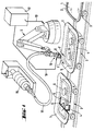
- Glazing 1 which is automotive glazing bulging in the case shown and which must be provided with a profiled frame 2 made of a polymer, are placed on mobile supports 3 and are brought one after the other to the station where the profiled frame 2 is put in place by extrusion. Glazing 1 is first prepared carefully in a previous workstation that is not shown, where their surface is cleaned in the area in which the framing must be put in place by extrusion and is coated with an adhesion primer which is adapted to the polymeric plastic material to be extruded.
- each support 3 comprises a chassis 4 corresponding to the shape of the glazing 1 and provided with an elastic support lining 5 thus that of several suction cups 6 thanks to which the glazing 1 is pressed against the support trim 5 of the chassis 4.
- the mobile supports 3 are then brought to a determined rate at the extrusion station in which the support carriage 3 is carefully positioned so that the glazing takes precisely its position for the work to be done, for example versus robot 9.
- the robot 9 comes into action. he brings the extrusion die 11 into its working position in first moving it in the direction of arrow F above from the edge of glazing 1, then making it follow the edge of glazing 1 in the direction of arrow F '.
- the die head 10 receives, via the control cable 18, orders from the central unit of command 12, which activates functions of the industry, such as engagement and interruption of the volume flow of the polymer, a modification of the orifice of the die or other functions.
- thermoplastic polymer is formed on the glazing 1.
- the thermoplastic polymer is melted in an extruder 15 and brought to the extrusion head 10 by a heated pressure hose 16.
- polymer thermoplastic you can use, for example, polypropylene thermoplastic polyolefin elastomers isotactic and ethylene-propylene-diene rubber.
- thermoplastic polymers it is indicated to heat the glazing, for example to a temperature about 150 ° C.
- reagents can also be used, for example example of reagents for polyurethanes hardenable humidity.
- the extruder 15 is replaced by a suitable pump which sends the material to be extruded to the head extrusion 10, by the flexible pressure hose 16.
- the extrusion head 10 When the extrusion head 10, after having made the glazing 1, returned to its starting position, the volume flow of the polymer is interrupted, the head extrusion 10 is discarded, in the opposite direction to that of the arrow F, of glazing 1 and glazing 1 provided with the frame 2 is brought to the next work station, while at the same time time, the next glazing 1 enters the extrusion station. The extrusion cycle then begins again.
- transition point between the beginning and the end of the extruded polymer bead inevitably presents deformations, due to the radial displacement of the die at the end of the extrusion operation.
- This transition point must therefore be retouched during an operation which follows.
- the retouching of the transition point can be done, for example, according to one of the processes which are the subject of documents EP 0 421 833 A2 or EP 0 524 060 A1.
- the retouching of the transition is particularly simple if we extrude a thermoplastic polymer because, in this case, it suffices to carry out additional pressing using a heated pressing.
- Fig. 2 shows the principle structure of a extrusion die used when glazing 1 must be equipped with a polymer 20 frame which, on one side of the glazing, that is to say on the side of the main surface 21, extends by its surface this main surface 21, at the same level, but, for the rest, has a cross section in L shape, the wings of the frame profile being contact respectively with the main surface 22 and with the peripheral edge 23 of the glazing and being firmly fixed on the surface of the glass.
- the extrusion die 25 has a notch 26 with a U-shaped section, continuous in the direction displacement, in which the edge of the glazing 1 engages.
- This U-shaped notch 26 is limited, on the side lower, by the jaw 27 whose upper surface 28, during the extrusion operation, is in contact with the main surface 21 of the glazing 1.
- the notch 26 of the die is formed by the jaw 29.
- the orifice calibrated of the die determines the cross section extruded polymer bead.
- the opening of the U of the sector is limited by the wall 30 of the movable strip 31.
- This strip 31 is mounted so as to be movable in the vertical direction. It can be reassembled by via rod 32, using the pneumatic cylinder or hydraulic 33. In the low position, the strip 31 is pressed against the surface 22 of the glazing 1 by springs helical 34 or other means producing the same effect.
- the bearing force exerted by the springs 34 must be adjusted by so that a good seal on the die surfaces 25 which slide on both sides of the glazing 1 is ensured.
- the contact pressure must not be too strong so that the friction forces do not become too important during the extrusion operation, which could, on the one hand, to impede the movement of the sector and, on the other hand, wear the sliding surfaces of this die.
- the jack 33 which actuates the sealing strip 31 is also controlled by the central control unit 12.
- the sealing strip 31 is brought into its final position high via cylinder 33 when die 25 is moved from its rest position to its working position on the edge of the glazing and when the die, at the end of the extrusion operation, is returned to its rest position next to the glazing.
- a lining 35, 36 made of elastic material having good sliding properties on glass.
- These fittings 35, 36 serve to better seal the opening of the die relative to glazing and to facilitate sliding.
- These fittings 35, 36 are advantageously mounted so that they can be replaced quickly.
- the die 40 shown in FIG. 3 is basically performed in a similar way to the sector 25 described with the aid of FIG. 2, but it differs from fact that it is provided, on both sides of the notch 41 in U-shape, movable sealing strips 42, 43.
- the sealing strips 42, 43 are here also pressed against the two main surfaces of glazing 1 by springs helical 44.
- Pneumatic or hydraulic cylinders 45, 46 bring the sealing strips through rods 47, 48, in their final open position, when the die is brought from its standby position to its position of work on the edge of the glazing and when, at the end of the extrusion operation, it is removed from the glazing 1.
- Des removable pads 49 made of elastic material having good sliding properties on glass, are also placed on the sliding surfaces of the two sealing strips 42, 43.
- the die 40 is suitable for the extrusion of a frame 52 which encloses the peripheral part of a glazing, on three sides, with a U-shaped section.
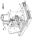
- Fig. 4 represents a die 55 produced following the principle described above, in its position of work in which the calibrated orifice 56 of the die is supplied with polymer to be extruded by two separate conduits 57 and 58.
- the flow of polymer in each of these conduits can be adjusted separately by suitable stop devices installed in these conduits or in the conduits which feed in polymer. It thus becomes possible to provide different parts of the orifice 56 section of the different volume flow rates if, as in the case shown, the cross section of the profile 60 of the framing is not symmetrical and that, consequently, a more material is needed in one part of the die orifice than in another part.
- a support roller 62 is, in addition, mounted on the extrusion head carrying the die 55, by through a support 63.
- This support roller 62 serves to compensate for the shape tolerances of glazing 1 in the direction perpendicular to the glazing surface, in particularly in the case of curved glazing.
- the extrusion head is mounted so that it can move from a few millimeters in the vertical direction, such so that the necessary compensation for tolerances takes place via the support roller 62.
Claims (8)
- Verfahren zum Herstellen einer Glasscheibe mit einer angeformten Polymer-Umrahmung, welche die Glasscheibe auf mindestens zwei Seiten (22, 23) umschließt, umfassend folgende Abschnitte :a) die Glasscheibe (1) wird in einer Bearbeitungsstation mit Hilfe einer Tragvorrichtung (3) stationär derart gehalten, daß ihr Rand frei über die Stützfläche (4,5) der Tragvorrichtung (3) übersteht,b) eine Extrusionsdüse (25), welche ein Düsenmaul mit einem U-förmigen Querschnitt hat, wird an den Rand der Glasscheibe (1) angenähert, der in diesen U-förmigen Querschnitt eingreift,c) gegen wenigstens eine Fläche (22) der Glasscheibe (1) wird eine bewegliche Dichtleiste (31) angedrückt, deren Seite (30) die Öffnung des U der Düse begrenzt, deren Rückwand die kalibrierte Öffnung besitzt, welche den Querschnitt des extrudierten Polymerstrangs bestimmt,d) nach dem Beginn des Ausströmens des Polymers wird die Düse verschoben, indem man sie dem Rand der Glasscheibe (1) folgen läßt,e) am Ende des Extrusionsvorgangs wird die bewegliche Leiste (31) in ihre abgerückte Endlage und die Düse in ihre Ruhestellung seitlich von der Glasscheibe gebracht.
- Verfahren nach Anspruch 1, dadurch gekennzeichnet, daß bei Verwendung einer einzigen beweglichen Dichtleiste (31) mit der Extrusionsdüse (25) die Fläche (28) der Backe (27) des U-förmigen Düsenmauls (26) während der Abschnitte c) und d) in Kontakt mit der Hauptfläche (21) der Glasscheibe steht.
- Verfahren nach Anspruch 1 dadurch gekennzeichnet, daß bei Verwendung zweier beweglicher Dichtleisten (42, 43) mit der Extrusionsdüse (40) diese während der Verfahrensschritte c) und d) auf die beiden Hauptflächen (21, 22) der Glasscheibe aufgedrückt werden und während der Verfahrensschritte b) und e) in ihrer geöffneten Endstellung stehen.
- Vorrichtung zum Ausführen des Verfahrens nach einem der Ansprüche 1 bis 3, umfassend einen Handhabungsroboter (9), ein die Glasscheibe (1) in der Bearbeitungsposition haltendes System Träger- und Transportsystem (3, 4, 5, 6), eine Einrichtung (15, 16) zum Liefern des zu extrudierenden Polymers, eine den Rand der Glasscheibe (1) umgreifende Extrusionsdüse (11, 25, 40, 55), die auf ihrer ganzen Länge mit einem U-förmigen Düsenmaul (26, 41) versehen ist mit einer in seine Rückseite eingeformten kalibrierten Düsenöffnung, gesehen in der Bewegungsrichtung der Düse, dadurch gekennzeichnet, daß mindestens eine der beiden Backen des U-förmigen Düsenmauls an ihrem vorderen Ende mit einer senkrecht zur korrespondierenden Hauptfläche der Glasscheibe beweglichen Dichtleiste (31) versehen ist, welche sich in Arbeitsstellung der Düse auf der Hauptfläche der Glasscheibe abstützt.
- Vorrichtung nach Anspruch 4 dadurch gekennzeichnet, daß die Extrusionsdüse (25) auf einer Seite des U-förmigen Düsenmauls (26) über die gesamte Länge der Düse eine bewegliche Dichtleiste (31) aufweist und auf der anderen Seite des U-förmigen Düsenmauls (26) eine ebene, zum gleitenden Kontakt mit der Hauptfläche (21) der Glasscheibe bestimmte Gleitfläche (28) aufweist.
- Vorrichtung nach einem der Ansprüche 4 oder 5, dadurch gekennzeichnet, daß die beim Extrusionsvorgang auf der Glasscheibe (1) gleitenden Flächen der Extrusionsdüse (25, 40) mit einer elastischen Auflage (35, 36) mit guten Gleiteigenschaften auf der Glasfläche versehen sind.
- Vorrichtung nach einem der Ansprüche 4 bis 6, dadurch gekennzeichnet, daß die Extrusionsdüse (55) zwei jeweils einen anderen Teil des Düsenquerschnitts der Düsenöffnung (56) mit dem zu extrudierenden Polymer versorgende Kanäle (57, 58) aufweist, in denen die Volumenströme des zu extrudierenden Polymers unabhängig voneinander regelbar sind.
- Vorrichtung nach einem der Ansprüche 4 bis 8, dadurch gekennzeichnet, daß der die Extrusionsdüse (55) tragende Extrusionskopf in Richtung senkrecht zur Glasscheibe (1) beweglich gelagert und mit einem sich auf der Glasscheibe (1) abstützenden Stützrad (62) zum Ausgleich von Formtoleranzen der Glasscheibe (1) versehen ist.
Priority Applications (1)
| Application Number | Priority Date | Filing Date | Title |
|---|---|---|---|
| SI9430175T SI0638408T1 (en) | 1993-08-09 | 1994-07-27 | Method and apparatus for making a window panel with a frame of polymeric material |
Applications Claiming Priority (2)
| Application Number | Priority Date | Filing Date | Title |
|---|---|---|---|
| DE4326650 | 1993-08-09 | ||
| DE4326650A DE4326650A1 (de) | 1993-08-09 | 1993-08-09 | Verfahren und Vorrichtungen zum Herstellen einer mit einem angeformten Rahmen aus einem Polymer versehenen Glasscheibe |
Publications (2)
| Publication Number | Publication Date |
|---|---|
| EP0638408A1 EP0638408A1 (de) | 1995-02-15 |
| EP0638408B1 true EP0638408B1 (de) | 1998-05-27 |
Family
ID=6494739
Family Applications (1)
| Application Number | Title | Priority Date | Filing Date |
|---|---|---|---|
| EP94401722A Expired - Lifetime EP0638408B1 (de) | 1993-08-09 | 1994-07-27 | Verfahren und Vorrichtung zur Herstellung einer mit einem angeformten Rahmen aus einem thermoplastischen Polymer versehene Glasscheibe |
Country Status (9)
| Country | Link |
|---|---|
| US (1) | US5507994A (de) |
| EP (1) | EP0638408B1 (de) |
| JP (1) | JP2889820B2 (de) |
| KR (1) | KR100343862B1 (de) |
| AT (1) | ATE166608T1 (de) |
| CZ (1) | CZ284346B6 (de) |
| DE (2) | DE4326650A1 (de) |
| ES (1) | ES2118341T3 (de) |
| SI (1) | SI0638408T1 (de) |
Families Citing this family (31)
| Publication number | Priority date | Publication date | Assignee | Title |
|---|---|---|---|---|
| USRE37341E1 (en) | 1993-08-09 | 2001-08-28 | Saint Gobain Vitrage | Device for extruding a polymer frame onto a plate-shaped object |
| US5645785A (en) * | 1993-08-09 | 1997-07-08 | Saint Gobain Vitrage | Device for extruding a polymer frame onto a plate-shaped object |
| FR2725657B1 (fr) * | 1994-10-17 | 1997-01-10 | Saint Gobain Vitrage | Dispositif pour l'extrusion d'un cordon profile en polymere sur un objet en forme de plaque |
| EP0672513B1 (de) * | 1994-02-28 | 1999-11-10 | Central Glass Company, Limited | Verfahren zum Strangpressen von Formteilen auf plattenförmige Gegenstände |
| US5846465A (en) * | 1995-03-16 | 1998-12-08 | Asahi Glass Company, Ltd. | Method for preparing a plate member for a window with a resinous frame |
| US5650031A (en) * | 1995-09-25 | 1997-07-22 | General Electric Company | Extruding thermoplastic insulation on stator bars |
| JP3369412B2 (ja) * | 1995-12-05 | 2003-01-20 | 東海興業株式会社 | 押出成形用ダイ装置 |
| DE19604397C1 (de) * | 1996-02-07 | 1997-07-31 | Sekurit Saint Gobain Deutsch | Vorrichtung zum Anextrudieren eines rahmenartigen Profilstrangs an eine Glasscheibe |
| JP3652436B2 (ja) * | 1996-04-30 | 2005-05-25 | 鬼怒川ゴム工業株式会社 | 自動車用ウィンドモール及び該ウィンドモールの押出成形装置 |
| JP3133260B2 (ja) * | 1996-09-02 | 2001-02-05 | 東海興業株式会社 | ウインドパネルの取付構造とその取付方法 |
| US6054001A (en) | 1998-02-17 | 2000-04-25 | Donnelly Corporation | Vehicle assembly line-side heat activation of a "ready-to-install" window fixing adhesive for attachment of a vehicle window to a vehicle |
| US6203639B1 (en) | 1998-02-17 | 2001-03-20 | Donnelly Corporation | Vehicle assembly line-side heat activation of a “ready-to-install” window fixing adhesive for attachment of a vehicle window to a vehicle |
| DE19961706B4 (de) * | 1999-12-21 | 2004-09-09 | Saint-Gobain Sekurit Deutschland Gmbh & Co. Kg | Verbindung einer Fahrzeugscheibe mit einem angrenzenden Bauteil |
| DE10023207A1 (de) * | 2000-05-12 | 2001-11-15 | Alstom Power Nv | Isolierung von Spulen |
| US6523983B2 (en) | 2000-08-18 | 2003-02-25 | Guide Corporation | Automotive lamp closeout and method of constructing same |
| DE10103865C1 (de) * | 2001-01-30 | 2002-05-02 | Saint Gobain Sekurit D Gmbh | Verfahren und Vorrichtung zum Herstellen eines Randprofils an einer Scheibe |
| EP1236559A1 (de) * | 2001-03-02 | 2002-09-04 | SOCIETA' ITALIANA VETRO- SIV-SpA | Vorrichtung und Verfahren zum Extrudieren eines Profils auf den Umfang einer Glasscheibe und Glasscheibe mit umgebender Profilleiste |
| DE10154553B4 (de) * | 2001-11-07 | 2005-06-09 | Saint-Gobain Sekurit Deutschland Gmbh & Co. Kg | Verfahren und Vorrichtung zum Herstellen eines Profilstrangs an einem Bauteil |
| US7043815B2 (en) | 2002-01-25 | 2006-05-16 | L & L Products, Inc. | Method for applying flowable materials |
| FI20031822A (fi) | 2003-12-12 | 2005-06-13 | Aulis Jaemiae | Menetelmä levyn reunaosan varustamiseksi listalla |
| US7180027B2 (en) * | 2004-03-31 | 2007-02-20 | L & L Products, Inc. | Method of applying activatable material to a member |
| US7951316B2 (en) * | 2005-04-05 | 2011-05-31 | Exxonmobil Chemical Patents Inc. | Process for pipe seal manufacture |
| US8123510B1 (en) * | 2008-03-24 | 2012-02-28 | Ebert Composite Corporation | Thermoplastic pultrusion die system and method |
| US8747098B1 (en) * | 2008-03-24 | 2014-06-10 | Ebert Composites Corporation | Thermoplastic pultrusion die system and method |
| FR2934180B1 (fr) * | 2008-07-28 | 2010-11-05 | Peugeot Citroen Automobiles Sa | Dispositif d'application d'un activateur de cordon de colle sur une glace de vehicule automobile. |
| JP5522268B2 (ja) * | 2011-06-14 | 2014-06-18 | 横浜ゴム株式会社 | グレージングガスケット付きガラスパネルの製造方法およびグレージングガスケット成形装置 |
| DE102011053583A1 (de) | 2011-09-14 | 2013-03-14 | Reis Group Holding Gmbh & Co. Kg | Plattenförmiges Modul sowie Verfahren zum Herstellen eines Rahmens für ein solches |
| GB201207481D0 (en) | 2012-04-26 | 2012-06-13 | Zephyros Inc | Applying flowable materials to synthetic substrates |
| WO2015124181A1 (de) | 2014-02-19 | 2015-08-27 | Webasto SE | Vorrichtung und verfahren zur herstellung einer umrandung eines flächig ausgedehnten panels |
| BE1022165B1 (fr) * | 2014-11-05 | 2016-02-22 | Splifar Sa | Procédé pour appliquer un joint à une plaque |
| DE102015224834B4 (de) * | 2015-12-10 | 2021-06-17 | Airbus Defence and Space GmbH | Extrusionsvorrichtung und Verfahren zum Auffüllen einer Nut mit einer Füllmasse |
Family Cites Families (15)
| Publication number | Priority date | Publication date | Assignee | Title |
|---|---|---|---|---|
| DE3008055A1 (de) * | 1980-03-03 | 1981-09-17 | Röhm GmbH, 6100 Darmstadt | Verfahren und formwerkzeug zur herstellung eines formkoerpers mit randprofil |
| EP0028284B1 (de) * | 1979-09-26 | 1983-12-28 | Röhm Gmbh | Wärmetauscher aus Kunststoff |
| GB2099688A (en) * | 1981-05-20 | 1982-12-15 | Drg Uk Ltd | A method of making cups and containers |
| FR2546812B1 (de) * | 1983-05-30 | 1986-04-18 | Saint Gobain Vitrage | |
| EP0337978A1 (de) * | 1988-04-11 | 1989-10-18 | Peter Lisec | Verfahren zum Füllen der Randfugen von Isolierglasscheiben mit Versiegelungsmasse |
| EP0354481B1 (de) * | 1988-08-09 | 1995-11-29 | Asahi Glass Company Ltd. | Verfahren zum Herstellen einer Glasscheibe mit einer Abdichtung und Form zum Herstellen einer solchen Glasscheibe |
| DE4006006C1 (de) * | 1990-02-26 | 1991-09-19 | Vegla Vereinigte Glaswerke Gmbh, 5100 Aachen, De | |
| DE4031236A1 (de) * | 1990-10-04 | 1992-04-09 | Ver Glaswerke Gmbh | Vorrichtung zum formen eines profilstrangs durch extrudieren unmittelbar auf dem rand einer glasscheibe |
| JP3056531B2 (ja) * | 1990-12-27 | 2000-06-26 | 東海興業株式会社 | シール体付きパネルの製造方法及び製造装置 |
| JP3212624B2 (ja) * | 1991-01-14 | 2001-09-25 | 東海興業株式会社 | パネル用枠体の製造方法とその製造装置 |
| DE4123588A1 (de) * | 1991-07-17 | 1993-01-21 | Ver Glaswerke Gmbh | Verfahren und vorrichtung zur herstellung eines fahrzeugfensters |
| DE69321649T2 (de) * | 1992-04-28 | 1999-04-15 | Asahi Glass Co Ltd | Verfahren zur Herstellung von Fensterglas mit Kunststoffrahmen |
| US5256361A (en) * | 1992-05-22 | 1993-10-26 | The Standard Products Company | Method for forming bodies comprising previously crosslinked thermally stable resin and product made thereby |
| US5358397A (en) * | 1993-05-10 | 1994-10-25 | L&L Products, Inc. | Apparatus for extruding flowable materials |
| US5382395A (en) * | 1993-05-14 | 1995-01-17 | Admiral Equipment Co. | Profile extrusion apparatus and method for extruding a profile |
-
1993
- 1993-08-09 DE DE4326650A patent/DE4326650A1/de not_active Withdrawn
-
1994
- 1994-07-27 AT AT94401722T patent/ATE166608T1/de active
- 1994-07-27 DE DE69410550T patent/DE69410550T2/de not_active Expired - Lifetime
- 1994-07-27 EP EP94401722A patent/EP0638408B1/de not_active Expired - Lifetime
- 1994-07-27 SI SI9430175T patent/SI0638408T1/xx unknown
- 1994-07-27 ES ES94401722T patent/ES2118341T3/es not_active Expired - Lifetime
- 1994-08-05 US US08/286,725 patent/US5507994A/en not_active Expired - Lifetime
- 1994-08-08 KR KR1019940019443A patent/KR100343862B1/ko not_active IP Right Cessation
- 1994-08-08 JP JP6185834A patent/JP2889820B2/ja not_active Expired - Lifetime
- 1994-08-09 CZ CZ941930A patent/CZ284346B6/cs not_active IP Right Cessation
Also Published As
| Publication number | Publication date |
|---|---|
| DE4326650A1 (de) | 1995-02-16 |
| DE69410550T2 (de) | 1998-12-17 |
| KR100343862B1 (ko) | 2002-11-29 |
| KR950005761A (ko) | 1995-03-20 |
| CZ193094A3 (en) | 1995-11-15 |
| DE69410550D1 (de) | 1998-07-02 |
| CZ284346B6 (cs) | 1998-10-14 |
| SI0638408T1 (en) | 1998-10-31 |
| EP0638408A1 (de) | 1995-02-15 |
| JP2889820B2 (ja) | 1999-05-10 |
| JPH07165441A (ja) | 1995-06-27 |
| US5507994A (en) | 1996-04-16 |
| ES2118341T3 (es) | 1998-09-16 |
| ATE166608T1 (de) | 1998-06-15 |
Similar Documents
| Publication | Publication Date | Title |
|---|---|---|
| EP0638408B1 (de) | Verfahren und Vorrichtung zur Herstellung einer mit einem angeformten Rahmen aus einem thermoplastischen Polymer versehene Glasscheibe | |
| EP0595667B1 (de) | Verfahren zum Herstellen einer Autoglasscheibe mit einem Umfangsrahmen aus Elastomermaterial mit bestimmter Formgebung | |
| EP0524060B1 (de) | Verfahren und Vorrichtung zum Herstellen einer Glasscheibe mit einem Umfangsrahmen auf Polymerbasis | |
| CA1225509A (fr) | Procede et dispositif de fabrication de vitrages surmoules et produits obtenus | |
| EP0421833B2 (de) | Verglasung mit einem Profilrahmen, insbesondere Fahrzeugverglasung, und Verfahren und Vorrichtung zu deren Herstellung | |
| CA1333626C (fr) | Vitrage isolant | |
| WO2001045974A1 (fr) | Assemblage d'une vitre de vehicule a un element contigu | |
| EP1441890B1 (de) | Verfahren und werkzeug zum umspritzen von glasscheiben mit einem kunststoffprofil. | |
| WO2004110720A1 (fr) | Procede de surmoulage de vitrages, joint d’etancheite et moule utilisable pour le procede | |
| FR2725657A1 (fr) | Dispositif pour l'extrusion d'un cordon profile en polymere sur un objet en forme de plaque | |
| EP1023154B1 (de) | Verfahren und vorrichtung zum formen eines teils einer auf einen gegenstand extrudierten profilleiste | |
| EP1796891B1 (de) | Verfahren und vorrichtung zur herstellung einer profilierten stange | |
| WO2018002502A1 (fr) | Procede de moulage d'un cordon profile affleurant sur un element vitre et dispositif de moulage pour ce procede | |
| EP0819050A1 (de) | Verfahren zum extrudieren eines profilrahmens auf verglasung und extrusionsdüse zur durchfürung dieses verfahrens | |
| EP0765211B1 (de) | Verfahren und vorrichtung zum nachformen eines extrudierten und auf ein objekt aufgebrachten profilstranges | |
| CA2207466A1 (fr) | Procede de finition d'un joint extrude in situ sur une plaque | |
| EP0823317B1 (de) | Formstempel und Verfahren zum Nachformen einer extrudierten Profilleiste auf einem Gegenstand | |
| FR2478773A1 (fr) | Profile d'etancheite a autoblocage ainsi que procede et installation pour le fabriquer | |
| FR2843068A1 (fr) | Procede d'elaboration d'un element de joint et vitrage ainsi obtenu | |
| FR2809659A1 (fr) | Procede et dispositif de pose en discontinu d'un tissu sur un profile polymere, du type joint d'etancheite | |
| FR2864919A1 (fr) | Cellule de pose dynamique en continu d'un joint d'etancheite adhesive sur un support de reception. |
Legal Events
| Date | Code | Title | Description |
|---|---|---|---|
| PUAI | Public reference made under article 153(3) epc to a published international application that has entered the european phase |
Free format text: ORIGINAL CODE: 0009012 |
|
| AK | Designated contracting states |
Kind code of ref document: A1 Designated state(s): AT BE DE ES FR GB IT LU NL PT SE |
|
| RAX | Requested extension states of the european patent have changed |
Free format text: SI PAYMENT 940801 |
|
| 17P | Request for examination filed |
Effective date: 19950503 |
|
| 17Q | First examination report despatched |
Effective date: 19961022 |
|
| GRAG | Despatch of communication of intention to grant |
Free format text: ORIGINAL CODE: EPIDOS AGRA |
|
| GRAG | Despatch of communication of intention to grant |
Free format text: ORIGINAL CODE: EPIDOS AGRA |
|
| GRAH | Despatch of communication of intention to grant a patent |
Free format text: ORIGINAL CODE: EPIDOS IGRA |
|
| GRAH | Despatch of communication of intention to grant a patent |
Free format text: ORIGINAL CODE: EPIDOS IGRA |
|
| RAP1 | Party data changed (applicant data changed or rights of an application transferred) |
Owner name: SAINT-GOBAIN VITRAGE |
|
| GRAA | (expected) grant |
Free format text: ORIGINAL CODE: 0009210 |
|
| AK | Designated contracting states |
Kind code of ref document: B1 Designated state(s): AT BE DE ES FR GB IT LU NL PT SE |
|
| AX | Request for extension of the european patent |
Free format text: SI PAYMENT 940801 |
|
| REF | Corresponds to: |
Ref document number: 166608 Country of ref document: AT Date of ref document: 19980615 Kind code of ref document: T |
|
| REF | Corresponds to: |
Ref document number: 69410550 Country of ref document: DE Date of ref document: 19980702 |
|
| ITF | It: translation for a ep patent filed |
Owner name: RACHELI & C. S.R.L. |
|
| GBT | Gb: translation of ep patent filed (gb section 77(6)(a)/1977) |
Effective date: 19980731 |
|
| REG | Reference to a national code |
Ref country code: ES Ref legal event code: FG2A Ref document number: 2118341 Country of ref document: ES Kind code of ref document: T3 |
|
| REG | Reference to a national code |
Ref country code: PT Ref legal event code: SC4A Free format text: AVAILABILITY OF NATIONAL TRANSLATION Effective date: 19980727 |
|
| PLBE | No opposition filed within time limit |
Free format text: ORIGINAL CODE: 0009261 |
|
| STAA | Information on the status of an ep patent application or granted ep patent |
Free format text: STATUS: NO OPPOSITION FILED WITHIN TIME LIMIT |
|
| 26N | No opposition filed | ||
| REG | Reference to a national code |
Ref country code: GB Ref legal event code: IF02 |
|
| REG | Reference to a national code |
Ref country code: SI Ref legal event code: IF |
|
| PGFP | Annual fee paid to national office [announced via postgrant information from national office to epo] |
Ref country code: LU Payment date: 20130715 Year of fee payment: 20 |
|
| PGFP | Annual fee paid to national office [announced via postgrant information from national office to epo] |
Ref country code: ES Payment date: 20130628 Year of fee payment: 20 Ref country code: PT Payment date: 20130128 Year of fee payment: 20 Ref country code: NL Payment date: 20130710 Year of fee payment: 20 Ref country code: AT Payment date: 20130626 Year of fee payment: 20 Ref country code: DE Payment date: 20130724 Year of fee payment: 20 Ref country code: SE Payment date: 20130711 Year of fee payment: 20 |
|
| PGFP | Annual fee paid to national office [announced via postgrant information from national office to epo] |
Ref country code: GB Payment date: 20130724 Year of fee payment: 20 Ref country code: FR Payment date: 20130715 Year of fee payment: 20 |
|
| PGFP | Annual fee paid to national office [announced via postgrant information from national office to epo] |
Ref country code: IT Payment date: 20130710 Year of fee payment: 20 |
|
| PGFP | Annual fee paid to national office [announced via postgrant information from national office to epo] |
Ref country code: BE Payment date: 20130830 Year of fee payment: 20 |
|
| REG | Reference to a national code |
Ref country code: DE Ref legal event code: R071 Ref document number: 69410550 Country of ref document: DE |
|
| BE20 | Be: patent expired |
Owner name: *SAINT-GOBAIN VITRAGE Effective date: 20140727 |
|
| REG | Reference to a national code |
Ref country code: PT Ref legal event code: MM4A Free format text: MAXIMUM VALIDITY LIMIT REACHED Effective date: 20140727 |
|
| REG | Reference to a national code |
Ref country code: NL Ref legal event code: V4 Effective date: 20140727 |
|
| REG | Reference to a national code |
Ref country code: GB Ref legal event code: PE20 Expiry date: 20140726 |
|
| REG | Reference to a national code |
Ref country code: AT Ref legal event code: MK07 Ref document number: 166608 Country of ref document: AT Kind code of ref document: T Effective date: 20140727 |
|
| REG | Reference to a national code |
Ref country code: SE Ref legal event code: EUG |
|
| PG25 | Lapsed in a contracting state [announced via postgrant information from national office to epo] |
Ref country code: DE Free format text: LAPSE BECAUSE OF EXPIRATION OF PROTECTION Effective date: 20140729 |
|
| REG | Reference to a national code |
Ref country code: ES Ref legal event code: FD2A Effective date: 20141120 |
|
| PG25 | Lapsed in a contracting state [announced via postgrant information from national office to epo] |
Ref country code: GB Free format text: LAPSE BECAUSE OF EXPIRATION OF PROTECTION Effective date: 20140726 |
|
| PG25 | Lapsed in a contracting state [announced via postgrant information from national office to epo] |
Ref country code: PT Free format text: LAPSE BECAUSE OF EXPIRATION OF PROTECTION Effective date: 20140805 |
|
| PG25 | Lapsed in a contracting state [announced via postgrant information from national office to epo] |
Ref country code: ES Free format text: LAPSE BECAUSE OF EXPIRATION OF PROTECTION Effective date: 20140728 |