EP0638408B1 - Method and apparatus for making a window panel with a frame of polymeric material - Google Patents
Method and apparatus for making a window panel with a frame of polymeric material Download PDFInfo
- Publication number
- EP0638408B1 EP0638408B1 EP94401722A EP94401722A EP0638408B1 EP 0638408 B1 EP0638408 B1 EP 0638408B1 EP 94401722 A EP94401722 A EP 94401722A EP 94401722 A EP94401722 A EP 94401722A EP 0638408 B1 EP0638408 B1 EP 0638408B1
- Authority
- EP
- European Patent Office
- Prior art keywords
- glazing
- die
- extrusion
- edge
- polymer
- Prior art date
- Legal status (The legal status is an assumption and is not a legal conclusion. Google has not performed a legal analysis and makes no representation as to the accuracy of the status listed.)
- Expired - Lifetime
Links
- 238000000034 method Methods 0.000 title claims abstract description 33
- 239000000463 material Substances 0.000 title description 6
- 238000001125 extrusion Methods 0.000 claims abstract description 70
- 229920000642 polymer Polymers 0.000 claims abstract description 33
- 238000007789 sealing Methods 0.000 claims abstract description 14
- 238000004519 manufacturing process Methods 0.000 claims abstract description 5
- 230000008569 process Effects 0.000 claims description 21
- 238000000465 moulding Methods 0.000 claims description 9
- 238000006073 displacement reaction Methods 0.000 claims description 6
- 239000011521 glass Substances 0.000 claims description 6
- 239000011324 bead Substances 0.000 claims description 5
- 230000000977 initiatory effect Effects 0.000 claims 1
- 230000002093 peripheral effect Effects 0.000 description 10
- 238000009432 framing Methods 0.000 description 8
- 229920001169 thermoplastic Polymers 0.000 description 8
- 239000003153 chemical reaction reagent Substances 0.000 description 5
- 230000008901 benefit Effects 0.000 description 4
- 230000007704 transition Effects 0.000 description 4
- 238000009434 installation Methods 0.000 description 3
- 239000013013 elastic material Substances 0.000 description 2
- 229920001971 elastomer Polymers 0.000 description 2
- 238000002347 injection Methods 0.000 description 2
- 239000007924 injection Substances 0.000 description 2
- 230000004048 modification Effects 0.000 description 2
- 238000012986 modification Methods 0.000 description 2
- 239000004033 plastic Substances 0.000 description 2
- 229920003023 plastic Polymers 0.000 description 2
- 229920002635 polyurethane Polymers 0.000 description 2
- 239000004814 polyurethane Substances 0.000 description 2
- 238000003825 pressing Methods 0.000 description 2
- 239000004416 thermosoftening plastic Substances 0.000 description 2
- 229920002943 EPDM rubber Polymers 0.000 description 1
- 239000004743 Polypropylene Substances 0.000 description 1
- 239000004809 Teflon Substances 0.000 description 1
- 229920006362 Teflon® Polymers 0.000 description 1
- 241000897276 Termes Species 0.000 description 1
- 230000009471 action Effects 0.000 description 1
- 230000000694 effects Effects 0.000 description 1
- 239000000806 elastomer Substances 0.000 description 1
- 238000005538 encapsulation Methods 0.000 description 1
- 238000001746 injection moulding Methods 0.000 description 1
- 239000002184 metal Substances 0.000 description 1
- 239000002861 polymer material Substances 0.000 description 1
- 238000006116 polymerization reaction Methods 0.000 description 1
- -1 polypropylene Polymers 0.000 description 1
- 229920001155 polypropylene Polymers 0.000 description 1
- 230000001681 protective effect Effects 0.000 description 1
- 235000013580 sausages Nutrition 0.000 description 1
- 229920002397 thermoplastic olefin Polymers 0.000 description 1
Images


Classifications
-
- C—CHEMISTRY; METALLURGY
- C03—GLASS; MINERAL OR SLAG WOOL
- C03B—MANUFACTURE, SHAPING, OR SUPPLEMENTARY PROCESSES
- C03B18/00—Shaping glass in contact with the surface of a liquid
- C03B18/02—Forming sheets
-
- B—PERFORMING OPERATIONS; TRANSPORTING
- B60—VEHICLES IN GENERAL
- B60J—WINDOWS, WINDSCREENS, NON-FIXED ROOFS, DOORS, OR SIMILAR DEVICES FOR VEHICLES; REMOVABLE EXTERNAL PROTECTIVE COVERINGS SPECIALLY ADAPTED FOR VEHICLES
- B60J10/00—Sealing arrangements
- B60J10/70—Sealing arrangements specially adapted for windows or windscreens
-
- B—PERFORMING OPERATIONS; TRANSPORTING
- B29—WORKING OF PLASTICS; WORKING OF SUBSTANCES IN A PLASTIC STATE IN GENERAL
- B29C—SHAPING OR JOINING OF PLASTICS; SHAPING OF MATERIAL IN A PLASTIC STATE, NOT OTHERWISE PROVIDED FOR; AFTER-TREATMENT OF THE SHAPED PRODUCTS, e.g. REPAIRING
- B29C48/00—Extrusion moulding, i.e. expressing the moulding material through a die or nozzle which imparts the desired form; Apparatus therefor
- B29C48/03—Extrusion moulding, i.e. expressing the moulding material through a die or nozzle which imparts the desired form; Apparatus therefor characterised by the shape of the extruded material at extrusion
- B29C48/12—Articles with an irregular circumference when viewed in cross-section, e.g. window profiles
-
- B—PERFORMING OPERATIONS; TRANSPORTING
- B29—WORKING OF PLASTICS; WORKING OF SUBSTANCES IN A PLASTIC STATE IN GENERAL
- B29C—SHAPING OR JOINING OF PLASTICS; SHAPING OF MATERIAL IN A PLASTIC STATE, NOT OTHERWISE PROVIDED FOR; AFTER-TREATMENT OF THE SHAPED PRODUCTS, e.g. REPAIRING
- B29C48/00—Extrusion moulding, i.e. expressing the moulding material through a die or nozzle which imparts the desired form; Apparatus therefor
- B29C48/15—Extrusion moulding, i.e. expressing the moulding material through a die or nozzle which imparts the desired form; Apparatus therefor incorporating preformed parts or layers, e.g. extrusion moulding around inserts
- B29C48/154—Coating solid articles, i.e. non-hollow articles
- B29C48/155—Partial coating thereof
-
- B—PERFORMING OPERATIONS; TRANSPORTING
- B29—WORKING OF PLASTICS; WORKING OF SUBSTANCES IN A PLASTIC STATE IN GENERAL
- B29C—SHAPING OR JOINING OF PLASTICS; SHAPING OF MATERIAL IN A PLASTIC STATE, NOT OTHERWISE PROVIDED FOR; AFTER-TREATMENT OF THE SHAPED PRODUCTS, e.g. REPAIRING
- B29C48/00—Extrusion moulding, i.e. expressing the moulding material through a die or nozzle which imparts the desired form; Apparatus therefor
- B29C48/25—Component parts, details or accessories; Auxiliary operations
- B29C48/30—Extrusion nozzles or dies
- B29C48/302—Extrusion nozzles or dies being adjustable, i.e. having adjustable exit sections
-
- C—CHEMISTRY; METALLURGY
- C03—GLASS; MINERAL OR SLAG WOOL
- C03B—MANUFACTURE, SHAPING, OR SUPPLEMENTARY PROCESSES
- C03B17/00—Forming molten glass by flowing-out, pushing-out, extruding or drawing downwardly or laterally from forming slits or by overflowing over lips
- C03B17/06—Forming glass sheets
-
- C—CHEMISTRY; METALLURGY
- C03—GLASS; MINERAL OR SLAG WOOL
- C03C—CHEMICAL COMPOSITION OF GLASSES, GLAZES OR VITREOUS ENAMELS; SURFACE TREATMENT OF GLASS; SURFACE TREATMENT OF FIBRES OR FILAMENTS MADE FROM GLASS, MINERALS OR SLAGS; JOINING GLASS TO GLASS OR OTHER MATERIALS
- C03C27/00—Joining pieces of glass to pieces of other inorganic material; Joining glass to glass other than by fusing
- C03C27/04—Joining glass to metal by means of an interlayer
- C03C27/048—Joining glass to metal by means of an interlayer consisting of an adhesive specially adapted for that purpose
Definitions
- the present invention relates to a method of manufacture of a plate-shaped object, provided with a polymer framing put in place by molding, especially glazing. It also relates to suitable devices for carrying out this process.
- profiles for frame or frame elements made of a polymer are placed by molding on the glazing using the extrusion process.
- reagents such as moisture curable polyurethane reagents or thermoplastic polymers can be used.
- processes of this kind are known, for example, from the texts of European patents or European patent applications 0 121 481, 0 258 128, 0 345 134, 0 421 833, 0 444 998, 0 479 677, 0 494 824, 0 524 060, 0 524 092, 0 531 201 and 0 537 067.
- the polymer rod extruded using an extrusion die is deposited on one of the main surfaces of the glazing, along its perimeter.
- the glazing is provided by molding with a polymer frame, which is molded L-shaped on the main surface inside and on the peripheral surface of the glazing and which, at the surface main exterior, i.e. the exterior face of the glazing, ends flush with this exterior surface of the glazing.
- Document EP-A-0 493 068 presents an extrusion method for producing a glazing fitted with a peripheral frame encasing the edges of the glazing on both surfaces and its song.
- the technique described uses a fixed extrusion die which has a lateral opening into which the edge of the glazing is introduced.
- the external form of bead is given by the section of the nozzle through which the material is extruded when the glazing is driven in front of the die.
- the upper and lower internal surfaces of side opening are equipped with fixed protective elements made of rubber which can compress elastically.
- Document EP-A-0 493 068 describes a process comprising steps a), b) and d) of claim 1 and a device having the characteristics of the preamble of the claim 4.
- a mold is presented in two. parts intended to allow the encapsulation of a glazing, that is to say the injection under high pressure of a polymer intended to create an elastomer frame at the periphery of the glazing.
- the invention relates to an additional seal housed in the mold plates and having elasticity in a direction perpendicular to the glazing to absorb its variations in shape while having sufficient rigidity to withstand the pressure plastic injection.
- An exemplary embodiment shows very clearly schematic a section of the trays of a mold where a peripheral groove has been arranged to serve as a housing for a metal seal covered with a layer of Teflon and associated with springs intended to ensure the desired flexibility.
- the invention aims to provide a method of manufacturing a glazing with a polymer frame, put in place by molding, which encloses the edge of the glazing less on two sides, i.e. at least on one of the main surfaces and on the peripheral side, this process should also be suitable for the production of small series.
- the process of the invention therefore takes advantage of the known advantages of the process extrusion to provide glazing with a frame set up by molding and made of a polymer, a frame which, until now, has been produced essentially using processes similar to injection molding, with complicated molds and large dimensions or, in the case of extrusion, with difficulty.
- With robots modern handling it is possible to carry out the head course control of extrusion all around the glazing with such precision that with the the invention, it is possible to produce glazings provided in this way with a frame, of which the outer contour has very tight tolerances. In this way, it is even possible to compensate for inevitable tolerances on the dimensions of the glazing, so that the precision of the dimensions of the glazing provided with their framing is higher than that glazing itself.
- the glazing to be fitted with its frame must be carefully positioned in the working area of the extrusion die and must be maintained on a support adapted to the shape of the glazing, so that the edge of this glazing is fully accessible to the extrusion head, at least in the part which must be provided with supervision.
- the glazing is equipped with framing on the whole of its perimeter.
- the extrusion die must then be produced in such a way that, together with the glazing, it delimits the cross section of extrusion. That means that the die must have sealing surfaces on both sides of the glazing which slide on the main surfaces of the glazing and which ensure a good seal of the cross section of the die relative to the glass surfaces. This is achieved according to the invention by means of sealing strips subjected to spring pressure, which are brought into their sealing position after the positioning of the die of extrusion on the edge of the glazing.
- the method of the invention it is possible to set up by extrusion on glazing polymer frames having a cross section substantially L-shaped and the surface of which, on one of the sides of the glazing, extends the main surface of the glazing. Framing of this kind is desired, for example, when, for aerodynamic reasons, glazing automobile must be mounted flush with the body.
- the extrusion die must be produced and piloted during extrusion so that the surface sector delimitation correspondent is in contact with the peripheral zone of the glazing up to the edge of the periphery and extends radially outwards the main surface of the glazing.
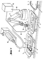
- Glazing 1 which is automotive glazing bulging in the case shown and which must be provided with a profiled frame 2 made of a polymer, are placed on mobile supports 3 and are brought one after the other to the station where the profiled frame 2 is put in place by extrusion. Glazing 1 is first prepared carefully in a previous workstation that is not shown, where their surface is cleaned in the area in which the framing must be put in place by extrusion and is coated with an adhesion primer which is adapted to the polymeric plastic material to be extruded.
- each support 3 comprises a chassis 4 corresponding to the shape of the glazing 1 and provided with an elastic support lining 5 thus that of several suction cups 6 thanks to which the glazing 1 is pressed against the support trim 5 of the chassis 4.
- the mobile supports 3 are then brought to a determined rate at the extrusion station in which the support carriage 3 is carefully positioned so that the glazing takes precisely its position for the work to be done, for example versus robot 9.
- the robot 9 comes into action. he brings the extrusion die 11 into its working position in first moving it in the direction of arrow F above from the edge of glazing 1, then making it follow the edge of glazing 1 in the direction of arrow F '.
- the die head 10 receives, via the control cable 18, orders from the central unit of command 12, which activates functions of the industry, such as engagement and interruption of the volume flow of the polymer, a modification of the orifice of the die or other functions.
- thermoplastic polymer is formed on the glazing 1.
- the thermoplastic polymer is melted in an extruder 15 and brought to the extrusion head 10 by a heated pressure hose 16.
- polymer thermoplastic you can use, for example, polypropylene thermoplastic polyolefin elastomers isotactic and ethylene-propylene-diene rubber.
- thermoplastic polymers it is indicated to heat the glazing, for example to a temperature about 150 ° C.
- reagents can also be used, for example example of reagents for polyurethanes hardenable humidity.
- the extruder 15 is replaced by a suitable pump which sends the material to be extruded to the head extrusion 10, by the flexible pressure hose 16.
- the extrusion head 10 When the extrusion head 10, after having made the glazing 1, returned to its starting position, the volume flow of the polymer is interrupted, the head extrusion 10 is discarded, in the opposite direction to that of the arrow F, of glazing 1 and glazing 1 provided with the frame 2 is brought to the next work station, while at the same time time, the next glazing 1 enters the extrusion station. The extrusion cycle then begins again.
- transition point between the beginning and the end of the extruded polymer bead inevitably presents deformations, due to the radial displacement of the die at the end of the extrusion operation.
- This transition point must therefore be retouched during an operation which follows.
- the retouching of the transition point can be done, for example, according to one of the processes which are the subject of documents EP 0 421 833 A2 or EP 0 524 060 A1.
- the retouching of the transition is particularly simple if we extrude a thermoplastic polymer because, in this case, it suffices to carry out additional pressing using a heated pressing.
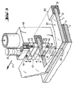
- Fig. 2 shows the principle structure of a extrusion die used when glazing 1 must be equipped with a polymer 20 frame which, on one side of the glazing, that is to say on the side of the main surface 21, extends by its surface this main surface 21, at the same level, but, for the rest, has a cross section in L shape, the wings of the frame profile being contact respectively with the main surface 22 and with the peripheral edge 23 of the glazing and being firmly fixed on the surface of the glass.
- the extrusion die 25 has a notch 26 with a U-shaped section, continuous in the direction displacement, in which the edge of the glazing 1 engages.
- This U-shaped notch 26 is limited, on the side lower, by the jaw 27 whose upper surface 28, during the extrusion operation, is in contact with the main surface 21 of the glazing 1.
- the notch 26 of the die is formed by the jaw 29.
- the orifice calibrated of the die determines the cross section extruded polymer bead.
- the opening of the U of the sector is limited by the wall 30 of the movable strip 31.
- This strip 31 is mounted so as to be movable in the vertical direction. It can be reassembled by via rod 32, using the pneumatic cylinder or hydraulic 33. In the low position, the strip 31 is pressed against the surface 22 of the glazing 1 by springs helical 34 or other means producing the same effect.
- the bearing force exerted by the springs 34 must be adjusted by so that a good seal on the die surfaces 25 which slide on both sides of the glazing 1 is ensured.
- the contact pressure must not be too strong so that the friction forces do not become too important during the extrusion operation, which could, on the one hand, to impede the movement of the sector and, on the other hand, wear the sliding surfaces of this die.
- the jack 33 which actuates the sealing strip 31 is also controlled by the central control unit 12.
- the sealing strip 31 is brought into its final position high via cylinder 33 when die 25 is moved from its rest position to its working position on the edge of the glazing and when the die, at the end of the extrusion operation, is returned to its rest position next to the glazing.
- a lining 35, 36 made of elastic material having good sliding properties on glass.
- These fittings 35, 36 serve to better seal the opening of the die relative to glazing and to facilitate sliding.
- These fittings 35, 36 are advantageously mounted so that they can be replaced quickly.
- the die 40 shown in FIG. 3 is basically performed in a similar way to the sector 25 described with the aid of FIG. 2, but it differs from fact that it is provided, on both sides of the notch 41 in U-shape, movable sealing strips 42, 43.
- the sealing strips 42, 43 are here also pressed against the two main surfaces of glazing 1 by springs helical 44.
- Pneumatic or hydraulic cylinders 45, 46 bring the sealing strips through rods 47, 48, in their final open position, when the die is brought from its standby position to its position of work on the edge of the glazing and when, at the end of the extrusion operation, it is removed from the glazing 1.
- Des removable pads 49 made of elastic material having good sliding properties on glass, are also placed on the sliding surfaces of the two sealing strips 42, 43.
- the die 40 is suitable for the extrusion of a frame 52 which encloses the peripheral part of a glazing, on three sides, with a U-shaped section.
- Fig. 4 represents a die 55 produced following the principle described above, in its position of work in which the calibrated orifice 56 of the die is supplied with polymer to be extruded by two separate conduits 57 and 58.
- the flow of polymer in each of these conduits can be adjusted separately by suitable stop devices installed in these conduits or in the conduits which feed in polymer. It thus becomes possible to provide different parts of the orifice 56 section of the different volume flow rates if, as in the case shown, the cross section of the profile 60 of the framing is not symmetrical and that, consequently, a more material is needed in one part of the die orifice than in another part.
- a support roller 62 is, in addition, mounted on the extrusion head carrying the die 55, by through a support 63.
- This support roller 62 serves to compensate for the shape tolerances of glazing 1 in the direction perpendicular to the glazing surface, in particularly in the case of curved glazing.
- the extrusion head is mounted so that it can move from a few millimeters in the vertical direction, such so that the necessary compensation for tolerances takes place via the support roller 62.
Abstract
Description
La présente invention concerne un procédé de fabrication d'un objet en forme de plaque, pourvu d'un encadrement en polymère mis en place par moulage, en particulier un vitrage. Elle concerne, en outre, des dispositifs appropriés servant à appliquer ce procédé.The present invention relates to a method of manufacture of a plate-shaped object, provided with a polymer framing put in place by molding, especially glazing. It also relates to suitable devices for carrying out this process.
On sait qu'il est possible d'équiper des vitrages
d'un encadrement fait d'un polymère suivant le bord du
vitrage, en engageant le vitrage entre deux demi-moules dans
lesquels ont été ménagées des cavités de moulage correspondant
au profil voulu pour l'encadrement et, après fermeture des
demi-moules, en remplissant les cavités de moulage d'un
polymère thermoplastique fondu ou des réactifs de
polymérisation. On emploie à grande échelle des procédés de ce
genre. Ils sont décrits, par exemple, dans les publications EP
0 127 546, EP 0 145 443, EP 0 333 538, DE 1 945 291, DE 3 714
176, DE 3 920 925, US 4 732 553 et US 4 830 804. Les procédés
de ce genre exigent des moules coûteux. En raison des coûts
considérables dus aux moules, ils ne sont pas rentables pour
les petites séries.We know that it is possible to equip glazing
a frame made of a polymer along the edge of the
glazing, by engaging the glazing between two half-molds in
which have been provided with corresponding molding cavities
to the desired profile for the framing and, after closing the
half-molds, filling the mold cavities with a
molten thermoplastic polymer or reagents
polymerization. Processes of this kind are used on a large scale
kind. They are described, for example, in EP publications
0 127 546, EP 0 145 443, EP 0 333 538,
Suivant un autre procédé connu, des profilés pour encadrement ou des éléments d'encadrement faits d'un polymère sont mis en place par moulage sur le vitrage à l'aide du procédé d'extrusion. Dans ce cas aussi, des réactifs, comme des réactifs pour polyuréthannes durcissables à l'humidité ou des polymères thermoplastiques peuvent être employés. Des procédés de ce genre sont connus, par exemple, par les textes de brevets européens ou de demandes de brevets européens 0 121 481, 0 258 128, 0 345 134, 0 421 833, 0 444 998, 0 479 677, 0 494 824, 0 524 060, 0 524 092, 0 531 201 et 0 537 067. Avec ces procédés connus, le boudin de polymère extrudé à l'aide d'une filière d'extrusion est déposé sur l'une des surfaces principales du vitrage, le long de son périmètre.According to another known method, profiles for frame or frame elements made of a polymer are placed by molding on the glazing using the extrusion process. In this case too, reagents, such as moisture curable polyurethane reagents or thermoplastic polymers can be used. Of processes of this kind are known, for example, from the texts of European patents or European patent applications 0 121 481, 0 258 128, 0 345 134, 0 421 833, 0 444 998, 0 479 677, 0 494 824, 0 524 060, 0 524 092, 0 531 201 and 0 537 067. With these known methods, the polymer rod extruded using an extrusion die is deposited on one of the main surfaces of the glazing, along its perimeter.
On a, en outre, proposé de réaliser un vitrage pourvu d'un encadrement fait d'un polymère en posant le vitrage sur une forme inférieure qui s'applique sur la surface inférieure du vitrage dans la partie périphérique de ce dernier et qui, au-delà de la surface périphérique du vitrage, constitue un prolongement de la surface du vitrage, et en extrudant, à l'aide d'une filière d'extrusion, sur le bord du vitrage, un boudin profilé qui fait saillie au-delà de la surface périphérique du vitrage et qui est limité par la surface du moule (DE-C-4 232 554). De cette façon, le vitrage est pourvu par moulage d'un encadrement en polymère, qui est moulé en forme de L sur la surface principale intérieure et sur la surface périphérique du vitrage et qui, au niveau de la surface principale extérieure, c'est-à-dire la face extérieure du vitrage, se termine au ras de cette surface extérieure du vitrage.It has also been proposed to produce a glazing provided with a frame made of a polymer by placing the glazing on a lower form which is applied to the surface lower glazing in the peripheral part of the latter and which, beyond the peripheral surface of the glazing, constitutes an extension of the glazing surface, and by extruding, using an extrusion die, on the edge of the glazing, a profiled rod which protrudes beyond the peripheral surface of the glazing and which is limited by the surface of the mold (DE-C-4 232 554). In this way, the glazing is provided by molding with a polymer frame, which is molded L-shaped on the main surface inside and on the peripheral surface of the glazing and which, at the surface main exterior, i.e. the exterior face of the glazing, ends flush with this exterior surface of the glazing.
Le document EP-A-0 493 068 présente une méthode d'extrusion pour réaliser un vitrage équipé d'un cadre périphérique enchâssant les bords du vitrage sur ses deux surfaces et son chant. La technique décrite utilise une filière d'extrusion fixe qui possède une ouverture latérale dans laquelle on introduit le bord du vitrage. La forme externe du cordon est donnée par la section de la buse par où le matériau est extrudé lorsque le vitrage est entrainé devant la filière. Les surfaces internes supérieure et inférieure de l'ouverture latérale sont équipées d'éléments de protection fixes faits d'un caoutchouc qui peut se comprimer élastiquement.Document EP-A-0 493 068 presents an extrusion method for producing a glazing fitted with a peripheral frame encasing the edges of the glazing on both surfaces and its song. The technique described uses a fixed extrusion die which has a lateral opening into which the edge of the glazing is introduced. The external form of bead is given by the section of the nozzle through which the material is extruded when the glazing is driven in front of the die. The upper and lower internal surfaces of side opening are equipped with fixed protective elements made of rubber which can compress elastically.
Le document EP-A-0 493 068 décrit un procédé comprenant les étapes a), b) et d) de
la revendication 1 ainsi qu'un dispositif ayant les caractéristiques du préambule de la
revendication 4.Document EP-A-0 493 068 describes a process comprising steps a), b) and d) of
Dans la demande de brevet EP-A-0 127 546, on présente un moule en deux parties destiné à permettre l'encapsulation d'un vitrage, c'est-à-dire l'injection sous haute pression d'un polymère destiné à créer à la périphérie du vitrage un cadre en élastomère. L'invention concerne un joint supplémentaire logé dans les plateaux du moule et présentant une élasticité dans une direction perpendiculaire au vitrage pour absorber ses variations de forme tout en présentant une rigidité suffisante pour supporter la pression d'injection de la matière plastique. Un exemple de réalisation montre de façon très schématique une coupe des plateaux d'un moule où une gorge périphérique a été ménagée pour servir de logement à un joint métallique recouvert d'une couche de Téflon et associé à des ressorts destinés à assurer la souplesse souhaitée. In patent application EP-A-0 127 546, a mold is presented in two. parts intended to allow the encapsulation of a glazing, that is to say the injection under high pressure of a polymer intended to create an elastomer frame at the periphery of the glazing. The invention relates to an additional seal housed in the mold plates and having elasticity in a direction perpendicular to the glazing to absorb its variations in shape while having sufficient rigidity to withstand the pressure plastic injection. An exemplary embodiment shows very clearly schematic a section of the trays of a mold where a peripheral groove has been arranged to serve as a housing for a metal seal covered with a layer of Teflon and associated with springs intended to ensure the desired flexibility.
L'invention a pour but de procurer un procédé de fabrication d'un vitrage avec un encadrement en polymère, mis en place par moulage, qui enserre le bord du vitrage au moins sur deux côtés, c'est-à-dire au moins sur l'une des surfaces principales et sur la face périphérique, ce procédé devant convenir aussi pour la production de petites séries.The invention aims to provide a method of manufacturing a glazing with a polymer frame, put in place by molding, which encloses the edge of the glazing less on two sides, i.e. at least on one of the main surfaces and on the peripheral side, this process should also be suitable for the production of small series.
Selon le procédé de l'invention, on fabrique un vitrage avec un encadrement en
polymère, mis en place par moulage, qui enserre le vitrage sur au moins deux côtés
présentant les étapes suivantes :
Le procédé de l'invention tire donc parti des avantages connus du procédé d'extrusion pour doter des vitrages d'un encadrement mis en place par moulage et fait d'un polymère, encadrement qui, jusqu'à présent, était réalisé essentiellement à l'aide de procédés analogues au moulage par injection, avec des moules compliqués et de grandes dimensions ou, dans le cas de l'extrusion, avec difficulté. Avec des robots de manutention modernes, il est possible de réaliser la commande de parcours de la tête d'extrusion tout autour du vitrage avec une précision telle, qu'avec les dispositifs de l'invention, on peut produire des vitrages pourvus de cette façon d'un encadrement, dont le contour extérieur présente des tolérances très serrées. De cette manière, il est même possible de compenser d'inévitables tolérances sur les cotes des vitrages, de telle sorte que la précision des cotes des vitrages pourvus de leur encadrement est supérieure à celle des vitrages eux-mêmes. Il est même possible d'utiliser des vitrages présentant de plus grandes tolérances des cotes, sans que cela influe sur les dimensions finales du vitrage avec son encadrement. L'avantage du procédé de l'invention qui présente une importance particulière réside toutefois dans le fait que, sans aucune modification des outils d'extrusion, on peut équiper d'un encadrement mis en place par moulage des vitrages ayant les formes et les dimensions les plus diverses. Pour cela, il est simplement nécessaire d'adapter le programme de parcours du robot de manutention à la forme considérée du vitrage.The process of the invention therefore takes advantage of the known advantages of the process extrusion to provide glazing with a frame set up by molding and made of a polymer, a frame which, until now, has been produced essentially using processes similar to injection molding, with complicated molds and large dimensions or, in the case of extrusion, with difficulty. With robots modern handling, it is possible to carry out the head course control of extrusion all around the glazing with such precision that with the the invention, it is possible to produce glazings provided in this way with a frame, of which the outer contour has very tight tolerances. In this way, it is even possible to compensate for inevitable tolerances on the dimensions of the glazing, so that the precision of the dimensions of the glazing provided with their framing is higher than that glazing itself. It is even possible to use glazing having more large dimensional tolerances, without affecting the final dimensions of the glazing with his coaching. The advantage of the process of the invention which has a of particular importance, however, is that, without any modification of the extrusion tools, we can equip a frame put in place by molding glazing with the most diverse shapes and dimensions. For this, it is simply necessary to adapt the handling robot's course program to the shape considered glazing.
Avec le procédé de l'invention, le vitrage à équiper de son encadrement doit être soigneusement positionné dans la zone de travail de la filière d'extrusion et doit être maintenu sur un support adapté à la forme du vitrage, de telle façon que le bord de ce vitrage soit pleinement accessible à la tête d'extrusion, au moins dans la partie qui doit être pourvue de l'encadrement. De préférence, le vitrage est équipé de l'encadrement sur la totalité de son périmètre. La filière d'extrusion doit alors être réalisée de telle façon que, conjointement avec le vitrage, elle délimite la section transversale d'extrusion. Cela signifie que la filière doit présenter, des deux côtés du vitrage, des surfaces d'étanchéité qui glissent sur les surfaces principales du vitrage et qui assurent une bonne étanchéité de la section transversale de la filière par rapport aux surfaces de verre. Cela est réalisé selon l'invention au moyen de réglettes d'étanchéité soumises à la pression de ressorts, qui sont amenées dans leur position d'étanchéité après le positionnement de la filière d'extrusion sur le bord du vitrage.With the method of the invention, the glazing to be fitted with its frame must be carefully positioned in the working area of the extrusion die and must be maintained on a support adapted to the shape of the glazing, so that the edge of this glazing is fully accessible to the extrusion head, at least in the part which must be provided with supervision. Preferably, the glazing is equipped with framing on the whole of its perimeter. The extrusion die must then be produced in such a way that, together with the glazing, it delimits the cross section of extrusion. That means that the die must have sealing surfaces on both sides of the glazing which slide on the main surfaces of the glazing and which ensure a good seal of the cross section of the die relative to the glass surfaces. This is achieved according to the invention by means of sealing strips subjected to spring pressure, which are brought into their sealing position after the positioning of the die of extrusion on the edge of the glazing.
Dans les techniques antérieures, il était possible d'utiliser une filière d'extrusion possédant des surfaces d'étanchéité disposées de façon rigide. Cela exige toutefois que les vitrages devant être pourvus de l'encadrement présentent de très faibles tolérances d'épaisseur et que les dimensions intérieures de l'ouverture de la filière soient adaptées avec une grande précision aux dimensions d'épaisseur des vitrages. Suivant la viscosité et les autres propriétés de la matière polymère utilisée, l'interstice entre une surface d'étanchéité de la filière d'extrusion et la surface du verre peut varier d'environ un à cinq dixièmes de millimètre. Avec de telles filières d'extrusion pourvues d'une ouverture de filière rigide, le boudin de polymère extrudé est enlevé à cet endroit par le déplacement de la filière lorsqu'on enlève cette dernière du vitrage à la fin de l'opération d'extrusion, mais, à cet endroit, le profilé de l'encadrement peut être rectifié sans problème, selon des méthodes connues.In the prior techniques, it was possible to use an extrusion die having rigidly arranged sealing surfaces. This requires however, the glazing to be provided with the framing have very low tolerances thick and that the interior dimensions of the opening of the sector are adapted with great precision to glazing thickness dimensions. Depending on the viscosity and the other properties of the polymer material used, the gap between a sealing surface of the die glass surface can vary from about one to five tenths of a millimeter. With such channels extrusion provided with a rigid die opening, the extruded polymer rod is removed there by the displacement of the die when the latter is removed from the glazing at the end of the extrusion operation, but at this right side, the frame profile can be adjusted without problem, according to known methods.
A l'aide du procédé de l'invention, il est possible de mettre en place par extrusion sur des vitrages des encadrements en polymère ayant une section transversale sensiblement en forme de L et dont la surface, sur l'un des côtés du vitrage, prolonge la surface principale du vitrage. Des encadrements de ce genre sont souhaités, par exemple, quand, pour des raisons d'aérodynamisme, des vitrages d'automobile doivent être montés à fleur de la carrosserie. Dans ce cas, la filière d'extrusion doit être réalisée et pilotée, lors de l'extrusion, de telle façon que la surface correspondante de délimitation de la filière soit en contact avec la zone périphérique du vitrage jusqu'au bord de la périphérie et prolonge radialement, vers l'extérieur, la surface principale du vitrage. Using the method of the invention, it is possible to set up by extrusion on glazing polymer frames having a cross section substantially L-shaped and the surface of which, on one of the sides of the glazing, extends the main surface of the glazing. Framing of this kind is desired, for example, when, for aerodynamic reasons, glazing automobile must be mounted flush with the body. In this case, the extrusion die must be produced and piloted during extrusion so that the surface sector delimitation correspondent is in contact with the peripheral zone of the glazing up to the edge of the periphery and extends radially outwards the main surface of the glazing.
Il est de même possible d'équiper le vitrage, à l'aide du procédé de l'invention, d'un encadrement qui enserre le bord du vitrage sur ses trois faces. L'encadrement extrudé peut alors en principe présenter une section transversale quelconque.It is also possible to equip the glazing, to using the method of the invention, a frame which encloses the edge of the glazing on its three faces. The extruded frame can then in principle have a cross section any.
D'autres particularités et avantages de l'invention
apparaítront dans la description qui va suivre, donnée avec
référence aux dessins annexés, dans lesquels :
La description qui suit concerne l'invention dans le cas de la mise en place par extrusion d'encadrements sur des vitrages, en particulier des vitrages d'automobiles. Toutefois, il y a lieu de signaler que, à l'aide du procédé de l'invention, d'autres objets en forme de plaque, par exemple des portes ou des éléments de construction en forme de plaque, peuvent être pourvus d'encadrements ou de joints d'étanchéité appropriés.The following description relates to the invention in the case of the installation by extrusion of frames on glazing, in particular automotive glazing. However, it should be noted that, using the process of the invention, other plate-shaped objects, for example doors or plate-shaped building elements, can be fitted with frames or seals appropriate.
Les vitrages 1, qui sont des vitrages d'automobiles
bombés dans le cas représenté et qui doivent être pourvus d'un
encadrement profilé 2 fait d'un polymère, sont posés sur des
supports mobiles 3 et sont amenés l'un après l'autre au poste
de travail où l'encadrement profilé 2 est mis en place par
extrusion. Les vitrages 1 sont tout d'abord préparés
soigneusement dans un poste de travail précédent qui n'est pas
représenté, où leur surface est nettoyée dans la zone dans
laquelle l'encadrement doit être mis en place par extrusion et
est revêtue d'un primaire d'adhérence qui est adapté à la
matière plastique polymère à extruder.
Les vitrages 1 ainsi préparés sont alors placés,
chacun dans une position précise sur le support 3
correspondant, où ils sont immobilisés par des dispositifs
appropriés, par exemple, à dépression. Dans ce but, chaque
support 3 comporte un châssis 4 correspondant à la forme du
vitrage 1 et pourvu d'une garniture d'appui élastique 5 ainsi
que de plusieurs ventouses 6 grâce auxquelles le vitrage 1 est
pressé contre la garniture d'appui 5 du châssis 4. Les
supports mobiles 3 sont alors amenés à une cadence déterminée
au poste d'extrusion dans lequel le chariot-support 3 est
soigneusement positionné de telle façon que le vitrage prenne
avec précision sa position pour le travail à accomplir, par
rapport au robot 9.The
Dès que le vitrage 1 a atteint la position qu'il
doit prendre pour l'extrusion, le robot 9 entre en action. Il
amène la filière d'extrusion 11 dans sa position de travail en
la déplaçant tout d'abord dans le sens de la flèche F au-dessus
du bord du vitrage 1, puis en lui faisant suivre le
bord du vitrage 1 dans le sens de la flèche F'. En même temps,
la tête de filière 10 reçoit alors, par l'intermédiaire du
câble de commande 18, des ordres de l'unité centrale de
commande 12, ce qui met en action des fonctions
supplémentaires de la filière, comme l'enclenchement et
l'interruption de l'écoulement volumique du polymère, une
modification de l'orifice de la filière ou d'autres fonctions.As soon as the
Il est évident que le système représenté qui utilise un robot pour déplacer la filière d'extrusion le long du bord du vitrage peut être conçu plus simplement quand le déplacement est produit par un opérateur. Alors un système d'alimentation adapté permet de déposer en chaque endroit la quantité de matière voulue pour que le boudin soit régulier.It is evident that the system represented which uses a robot to move the extrusion die along from the edge of the glazing can be designed more simply when the displacement is produced by an operator. So a system suitable power supply allows to deposit in each place the amount of material required for the sausage to be regular.
Dans le cas représenté, un polymère thermoplastique
est formé sur le vitrage 1. Le polymère thermoplastique est
fondu dans une extrudeuse 15 et amené à la tête d'extrusion 10
par un tuyau flexible sous pression chauffé 16. Comme polymère
thermoplastique, on peut utiliser, par exemple, des
élastomères de polyoléfines thermoplastiques en polypropylène
isotactique et du caoutchouc d'éthylène-propylène-diène. Lors
de l'utilisation de polymères thermoplastiques, il est indiqué
de réchauffer les vitrages, par exemple à une température
d'environ 150°C. Cependant, au lieu de polymères
thermoplastiques, on peut aussi utiliser des réactifs, par
exemple des réactifs pour polyuréthannes durcissables à
l'humidité. Dans ce cas, l'extrudeuse 15 est remplacée par une
pompe appropriée qui envoit la matière à extruder vers la tête
d'extrusion 10, par le tuyau flexible sous pression 16.In the case shown, a thermoplastic polymer
is formed on the
Quand la tête d'extrusion 10, après avoir fait le
tour du vitrage 1, est revenue dans sa position de départ,
l'écoulement volumique du polymère est interrompu, la tête
d'extrusion 10 est écartée, dans le sens opposé à celui de la
flèche F, du vitrage 1 et le vitrage 1 pourvu de l'encadrement
2 est amené au poste de travail suivant, tandis que, en même
temps, le vitrage 1 suivant pénètre dans le poste d'extrusion.
Le cycle d'extrusion recommence alors.When the
Le point de transition entre le début et la fin du cordon de polymère extrudé présente inévitablement des déformations, à cause du déplacement radial de la filière à la fin de l'opération d'extrusion. Ce point de transition doit donc être retouché au cours d'une opération qui suit. La retouche du point de transition peut se faire, par exemple, suivant l'un des procédés faisant l'objet des documents EP 0 421 833 A2 ou EP 0 524 060 A1. La retouche de la zone de transition est particulièrement simple si l'on extrude un polymère thermoplastique car, dans ce cas, il suffit de procéder à un pressage complémentaire à l'aide d'un outil de pressage chauffé.The transition point between the beginning and the end of the extruded polymer bead inevitably presents deformations, due to the radial displacement of the die at the end of the extrusion operation. This transition point must therefore be retouched during an operation which follows. The retouching of the transition point can be done, for example, according to one of the processes which are the subject of documents EP 0 421 833 A2 or EP 0 524 060 A1. The retouching of the transition is particularly simple if we extrude a thermoplastic polymer because, in this case, it suffices to carry out additional pressing using a heated pressing.
La Fig. 2 montre la structure de principe d'une
filière d'extrusion utilisée quand un vitrage 1 doit être
équipé d'un encadrement en polymère 20 qui, d'un côté du
vitrage, c'est-à-dire du côté de la surface principale 21,
prolonge par sa surface cette surface principale 21, au même
niveau, mais, pour le reste, a une section transversale en
forme de L, les ailes du profilé d'encadrement étant en
contact respectivement avec la surface principale 22 et avec
le chant périphérique 23 du vitrage et étant solidement fixées
à la surface du verre.Fig. 2 shows the principle structure of a
extrusion die used when glazing 1 must be
equipped with a
La filière d'extrusion 25 présente une échancrure
26 avec une section en forme de U, continue dans la direction
du déplacement, dans laquelle s'engage le bord du vitrage 1.
Cette échancrure 26 en forme de U est limitée, du côté
inférieur, par le mors 27 dont la surface supérieure 28,
pendant l'opération d'extrusion, est en contact avec la
surface principale 21 du vitrage 1. Du côté supérieur,
l'échancrure 26 de la filière est formée par le mors 29.The extrusion die 25 has a
Dans la paroi arrière de la filière, vue dans le
sens du déplacement de la filière 25, se trouve l'orifice
calibré de la filière, qui détermine la section transversale
du cordon de polymère extrudé. L'ouverture du U de la filière
est limitée par la paroi 30 de la réglette mobile 31. Cette
réglette 31 est montée de façon à être mobile dans la
direction verticale. Elle peut être remontée par
l'intermédiaire de la tige 32, à l'aide du vérin pneumatique
ou hydraulique 33. En position basse, la réglette 31 est
pressée contre la surface 22 du vitrage 1 par des ressorts
hélicoïdaux 34 ou d'autres moyens produisant le même effet. La
force d'appui exercée par les ressorts 34 doit être réglée de
telle façon qu'une bonne étanchéité des surfaces de la filière
25 qui glissent sur les deux faces du vitrage 1 soit assurée.
D'autre part, la pression d'appui ne doit pas être trop forte
afin que les forces de frottement ne deviennent pas trop
importantes lors de l'opération d'extrusion, ce qui pourrait,
d'une part, gêner le mouvement de la filière et, d'autre part,
user les surfaces de glissement de cette filière.In the rear wall of the die, seen in the
direction of movement of the die 25, is the orifice
calibrated of the die, which determines the cross section
extruded polymer bead. The opening of the U of the sector
is limited by the
Le vérin 33 qui actionne la réglette d'étanchéité
31 est également piloté par l'unité centrale de commande 12.
La réglette d'étanchéité 31 est amenée dans sa position finale
haute par l'intermédiaire du vérin 33 quand la filière 25 est
déplacée de sa position de repos vers sa position de travail
sur le bord du vitrage et quand la filière, au terme de
l'opération d'extrusion, est ramenée dans sa position de repos
à côté du vitrage. The
Sur chacune des surfaces de glissement de la
filière 25, à savoir la surface 27 de l'échancrure 26 et la
face inférieure de la réglette 31, est disposée une garniture
35, 36 faite d'une matière élastique ayant de bonnes
propriétés de glissement sur le verre. Ces garnitures 35, 36
servent à mieux étancher l'ouverture de la filière par rapport
au vitrage et à faciliter le glissement. Ces garnitures 35, 36
sont avantageusement montées de manière à pouvoir être
remplacées rapidement.On each of the sliding surfaces of the
die 25, namely the
La filière 40 représentée sur la Fig. 3 est
fondamentalement réalisée d'une façon analogue à la filière 25
décrite à l'aide de la Fig. 2, mais elle s'en distingue du
fait qu'elle est pourvue, des deux côtés de l'échancrure 41 en
forme de U, de réglettes d'étanchéité mobiles 42, 43. Les
réglettes d'étanchéité 42, 43 sont ici aussi pressées contre
les deux surfaces principales du vitrage 1 par des ressorts
hélicoïdaux 44. Les vérins pneumatiques ou hydrauliques 45, 46
amènent les réglettes d'étanchéité par l'intermédiaire de
tiges 47, 48, dans leur position finale ouverte, quand la
filière est amenée de sa position d'attente à sa position de
travail sur le bord du vitrage et quand, au terme de
l'opération d'extrusion, elle est retirée du vitrage 1. Des
garnitures amovibles 49, faites d'une matière élastique ayant
de bonnes propriétés de glissement sur le verre, sont
également placées sur les surfaces de glissement des deux
réglettes d'étanchéité 42, 43.The die 40 shown in FIG. 3 is
basically performed in a similar way to the sector 25
described with the aid of FIG. 2, but it differs from
fact that it is provided, on both sides of the
La filière 40 convient pour l'extrusion d'un
encadrement 52 qui enserre la partie périphérique d'un
vitrage, sur les trois côtés, avec une section en U. The
La Fig. 4 représente une filière 55 réalisée
suivant le principe décrit plus haut, dans sa position de
travail dans laquelle l'orifice calibré 56 de la filière est
alimenté, en polymère à extruder par deux conduits séparés 57
et 58. Le débit de polymère dans chacun de ces conduits peut
être réglé séparément par des dispositifs d'arrêt appropriés
installés dans ces conduits ou dans les conduites qui les
alimentent en polymère. Il devient ainsi possible de fournir à
différentes parties de la section de l'orifice 56 de la
filière des débits volumiques différents si, comme dans le cas
représenté, la section transversale du profilé 60 de
l'encadrement n'est pas symétrique et que, par conséquent, une
plus grande quantité de matière est nécessaire dans une partie
de l'orifice de la filière que dans une autre partie.Fig. 4 represents a die 55 produced
following the principle described above, in its position of
work in which the calibrated
Dans ce cas, un galet d'appui 62 est, en outre,
monté sur la tête d'extrusion portant la filière 55, par
l'intermédiaire d'un support 63. Ce galet d'appui 62 sert à
compenser les tolérances de forme du vitrage 1 dans la
direction perpendiculaire à la surface du vitrage, en
particulier dans le cas des vitrages bombés. Dans ce but, la
tête d'extrusion est montée de façon à pouvoir bouger de
quelques millimètres dans la direction verticale, de telle
sorte que la compensation nécessaire des tolérances s'effectue
par l'intermédiaire du galet d'appui 62.In this case, a
Claims (8)
- Process for the production of a glazing with a polymer frame, put into place by moulding and which encloses the glazing on at least two sides (22, 23), having the following stages:a) the glazing (1) is supplied to the work station where it is kept stationary with the aid of a support device (3), its edge projecting freely beyond the bearing surfaces of the support (3),b) an extrusion die (25) is moved towards the edge of the glazing (1), the latter having a notch (26) with a U-shaped cross-section and in which engages the edge of the glazing,c) against at least one surface (22) of the glazing is pressed a mobile ledge (31), whose wall (30) limits the opening of the U of the die, the rear wall of the latter having the gauged orifice, which determines the cross-section of the extruded polymer bead,d) after initiating the flow of polymer, the die is moved making it follow the edge of the glazing (1),e) during the extrusion Operation, the mobile ledge (31) is brought into its final, spaced apart position and the die into its rest position close to the glazing.
- Process according to claim 1, characterized in that when a single mobile ledge (31) equips the extrusion die (25), the jaw (27) of the U-shaped notch (26) has, during stages c) and d), its surface (28) in contact with the glazing surface (21).
- Process according to claim 1, characterized in that when two mobile ledges (42, 43) equip the extrusion die (40), they are pressed onto the two surfaces (21, 22) of the glazing during stages c) and d) of the process and are in their final, open position during stages b) and e) of the process.
- Device for performing the process according to one of the claims 1 to 3, having a handling robot (9), a support and displacement system (3, 4, 5, 6) maintaining the glazing (1) in the operative position, a mechanism (15, 16) supplying the polymer to be extruded, an extrusion die (11, 25, 40, 55) enclosing the edge of the glazing (1), is provided over its entire length with a U-shaped notch (26, 41), with a gauged die orifice made in its rear face, seen in the die displacement direction, characterized in that at least one of the two jaws of the U-shaped notch of the die is provided, at its front end, with a sealing ledge (31) movable perpendicular to the corresponding, main surface of the glazing and which, in the operative position of the die, bears on the glazing surface.
- Device according to claim 4, characterized in that the extrusion die (25), has on one side of the U-shaped notch (26) over the entire die length, a mobile sealing ledge (31) and, on the other side of the U-shaped notch (26), a planar sliding surface (28) for sliding contact with the main surface (21) of the glazing.
- Device according to one of the claims 4 or 5, characterized in that the surfaces of the extrusion die (25, 40) sliding, during the extrusion operation, on the glazing (1), are provided with an elastic covering (35, 36) having good sliding properties on the glass surface.
- Device according to one of the claims 4 to 6, characterized in that the extrusion die (55) has two ducts (57, 58), each of which supplies a different part of the cross-section of the orifice (56) of the die by means of the polymer to be extruded, the volume flow rates of the polymer to be extruded being regulatable independently of one another in said ducts.
- Device according to one of the claims 4 to 7, characterized in that the extrusion head carrying the extrusion die (55) is installed so as to be mobile in the direction perpendicular to the glazing (1) and is provided with a bearing roller (62), which bears on the glazing (1) in order to compensate shape tolerances of said glazing (1).
Priority Applications (1)
| Application Number | Priority Date | Filing Date | Title |
|---|---|---|---|
| SI9430175T SI0638408T1 (en) | 1993-08-09 | 1994-07-27 | Method and apparatus for making a window panel with a frame of polymeric material |
Applications Claiming Priority (2)
| Application Number | Priority Date | Filing Date | Title |
|---|---|---|---|
| DE4326650A DE4326650A1 (en) | 1993-08-09 | 1993-08-09 | Method and devices for producing a glass pane provided with a molded-on frame made of a polymer |
| DE4326650 | 1993-08-09 |
Publications (2)
| Publication Number | Publication Date |
|---|---|
| EP0638408A1 EP0638408A1 (en) | 1995-02-15 |
| EP0638408B1 true EP0638408B1 (en) | 1998-05-27 |
Family
ID=6494739
Family Applications (1)
| Application Number | Title | Priority Date | Filing Date |
|---|---|---|---|
| EP94401722A Expired - Lifetime EP0638408B1 (en) | 1993-08-09 | 1994-07-27 | Method and apparatus for making a window panel with a frame of polymeric material |
Country Status (9)
| Country | Link |
|---|---|
| US (1) | US5507994A (en) |
| EP (1) | EP0638408B1 (en) |
| JP (1) | JP2889820B2 (en) |
| KR (1) | KR100343862B1 (en) |
| AT (1) | ATE166608T1 (en) |
| CZ (1) | CZ284346B6 (en) |
| DE (2) | DE4326650A1 (en) |
| ES (1) | ES2118341T3 (en) |
| SI (1) | SI0638408T1 (en) |
Families Citing this family (31)
| Publication number | Priority date | Publication date | Assignee | Title |
|---|---|---|---|---|
| FR2725657B1 (en) * | 1994-10-17 | 1997-01-10 | Saint Gobain Vitrage | DEVICE FOR EXTRUDING A PROFILED POLYMER CORD ON A PLATE-SHAPED OBJECT |
| US5645785A (en) * | 1993-08-09 | 1997-07-08 | Saint Gobain Vitrage | Device for extruding a polymer frame onto a plate-shaped object |
| USRE37341E1 (en) | 1993-08-09 | 2001-08-28 | Saint Gobain Vitrage | Device for extruding a polymer frame onto a plate-shaped object |
| EP0672513B1 (en) * | 1994-02-28 | 1999-11-10 | Central Glass Company, Limited | Method of extruding moulding on plate-like articles |
| US5846465A (en) * | 1995-03-16 | 1998-12-08 | Asahi Glass Company, Ltd. | Method for preparing a plate member for a window with a resinous frame |
| US5650031A (en) * | 1995-09-25 | 1997-07-22 | General Electric Company | Extruding thermoplastic insulation on stator bars |
| JP3369412B2 (en) * | 1995-12-05 | 2003-01-20 | 東海興業株式会社 | Extrusion die equipment |
| DE19604397C1 (en) * | 1996-02-07 | 1997-07-31 | Sekurit Saint Gobain Deutsch | Device for extruding a frame-like profile strand onto a glass pane |
| JP3652436B2 (en) * | 1996-04-30 | 2005-05-25 | 鬼怒川ゴム工業株式会社 | Wind molding for automobile and extrusion molding apparatus for the wind molding |
| JP3133260B2 (en) * | 1996-09-02 | 2001-02-05 | 東海興業株式会社 | Wind panel mounting structure and mounting method |
| US6203639B1 (en) | 1998-02-17 | 2001-03-20 | Donnelly Corporation | Vehicle assembly line-side heat activation of a “ready-to-install” window fixing adhesive for attachment of a vehicle window to a vehicle |
| US6054001A (en) | 1998-02-17 | 2000-04-25 | Donnelly Corporation | Vehicle assembly line-side heat activation of a "ready-to-install" window fixing adhesive for attachment of a vehicle window to a vehicle |
| DE19961706B4 (en) | 1999-12-21 | 2004-09-09 | Saint-Gobain Sekurit Deutschland Gmbh & Co. Kg | Connection of a vehicle window to an adjacent component |
| DE10023207A1 (en) * | 2000-05-12 | 2001-11-15 | Alstom Power Nv | Coil insulation |
| US6523983B2 (en) | 2000-08-18 | 2003-02-25 | Guide Corporation | Automotive lamp closeout and method of constructing same |
| DE10103865C1 (en) * | 2001-01-30 | 2002-05-02 | Saint Gobain Sekurit D Gmbh | Formation of edging profile on a pane of two sheets of glass held together by an adhesive, comprises forming the edging on a pane whose shape is determined by the shape of a molding bed, no adhesion promoter being present on edge of pane |
| EP1236559A1 (en) * | 2001-03-02 | 2002-09-04 | SOCIETA' ITALIANA VETRO- SIV-SpA | Apparatus and process for extruding a profile on a glazing and glazing having extruded profile |
| DE10154553B4 (en) * | 2001-11-07 | 2005-06-09 | Saint-Gobain Sekurit Deutschland Gmbh & Co. Kg | Method and device for producing a profile strand on a component |
| US7043815B2 (en) * | 2002-01-25 | 2006-05-16 | L & L Products, Inc. | Method for applying flowable materials |
| FI20031822A (en) | 2003-12-12 | 2005-06-13 | Aulis Jaemiae | Procedure for providing a flat edge with a strip |
| US7180027B2 (en) * | 2004-03-31 | 2007-02-20 | L & L Products, Inc. | Method of applying activatable material to a member |
| US7951316B2 (en) * | 2005-04-05 | 2011-05-31 | Exxonmobil Chemical Patents Inc. | Process for pipe seal manufacture |
| US8747098B1 (en) * | 2008-03-24 | 2014-06-10 | Ebert Composites Corporation | Thermoplastic pultrusion die system and method |
| US8123510B1 (en) * | 2008-03-24 | 2012-02-28 | Ebert Composite Corporation | Thermoplastic pultrusion die system and method |
| FR2934180B1 (en) * | 2008-07-28 | 2010-11-05 | Peugeot Citroen Automobiles Sa | DEVICE FOR APPLYING A GLUE CORD ACTIVATOR TO A MOTOR VEHICLE ICE. |
| DE112012002462B4 (en) * | 2011-06-14 | 2016-01-07 | The Yokohama Rubber Co., Ltd. | Method and device for producing a glass plate with a glazing gasket |
| DE102011053583A1 (en) | 2011-09-14 | 2013-03-14 | Reis Group Holding Gmbh & Co. Kg | Plate-shaped module and method for producing a frame for such |
| GB201207481D0 (en) | 2012-04-26 | 2012-06-13 | Zephyros Inc | Applying flowable materials to synthetic substrates |
| CN106029349B (en) | 2014-02-19 | 2018-01-12 | 韦巴斯托股份公司 | For the apparatus and method at the edge for manufacturing flat extension board |
| BE1022165B1 (en) * | 2014-11-05 | 2016-02-22 | Splifar Sa | Method for applying a seal to a plate |
| DE102015224834B4 (en) * | 2015-12-10 | 2021-06-17 | Airbus Defence and Space GmbH | Extrusion device and method for filling a groove with a filling compound |
Family Cites Families (15)
| Publication number | Priority date | Publication date | Assignee | Title |
|---|---|---|---|---|
| EP0028284B1 (en) * | 1979-09-26 | 1983-12-28 | Röhm Gmbh | Heat exchanger of plastics material |
| DE3008055A1 (en) * | 1980-03-03 | 1981-09-17 | Röhm GmbH, 6100 Darmstadt | Article, esp. heat exchanger, provided with extruded edge - esp. of same thermoplastic to form one-piece sealed, durable bond |
| GB2099688A (en) * | 1981-05-20 | 1982-12-15 | Drg Uk Ltd | A method of making cups and containers |
| FR2546812B1 (en) * | 1983-05-30 | 1986-04-18 | Saint Gobain Vitrage | |
| EP0337978A1 (en) * | 1988-04-11 | 1989-10-18 | Peter Lisec | Method for filling the peripheral edge joints of double glazings with a sealant |
| DE68924938T2 (en) * | 1988-08-09 | 1996-07-25 | Asahi Glass Co Ltd | Method of making a glass sheet with a seal and mold for making such a glass sheet. |
| DE4006006C1 (en) * | 1990-02-26 | 1991-09-19 | Vegla Vereinigte Glaswerke Gmbh, 5100 Aachen, De | |
| DE4031236A1 (en) * | 1990-10-04 | 1992-04-09 | Ver Glaswerke Gmbh | DEVICE FOR SHAPING A PROFILE STRAND BY EXTRUDING DIRECTLY ON THE EDGE OF A GLASS DISC |
| JP3056531B2 (en) * | 1990-12-27 | 2000-06-26 | 東海興業株式会社 | Method and apparatus for manufacturing panel with seal |
| JP3212624B2 (en) * | 1991-01-14 | 2001-09-25 | 東海興業株式会社 | Panel frame manufacturing method and manufacturing apparatus |
| DE4123588A1 (en) * | 1991-07-17 | 1993-01-21 | Ver Glaswerke Gmbh | METHOD AND DEVICE FOR PRODUCING A VEHICLE WINDOW |
| EP0568014B1 (en) * | 1992-04-28 | 1998-10-21 | Asahi Glass Company Ltd. | Method of making a window panel with a synthetic resin frame |
| US5256361A (en) * | 1992-05-22 | 1993-10-26 | The Standard Products Company | Method for forming bodies comprising previously crosslinked thermally stable resin and product made thereby |
| US5358397A (en) * | 1993-05-10 | 1994-10-25 | L&L Products, Inc. | Apparatus for extruding flowable materials |
| US5382395A (en) * | 1993-05-14 | 1995-01-17 | Admiral Equipment Co. | Profile extrusion apparatus and method for extruding a profile |
-
1993
- 1993-08-09 DE DE4326650A patent/DE4326650A1/en not_active Withdrawn
-
1994
- 1994-07-27 SI SI9430175T patent/SI0638408T1/en unknown
- 1994-07-27 AT AT94401722T patent/ATE166608T1/en active
- 1994-07-27 EP EP94401722A patent/EP0638408B1/en not_active Expired - Lifetime
- 1994-07-27 DE DE69410550T patent/DE69410550T2/en not_active Expired - Lifetime
- 1994-07-27 ES ES94401722T patent/ES2118341T3/en not_active Expired - Lifetime
- 1994-08-05 US US08/286,725 patent/US5507994A/en not_active Expired - Lifetime
- 1994-08-08 KR KR1019940019443A patent/KR100343862B1/en not_active IP Right Cessation
- 1994-08-08 JP JP6185834A patent/JP2889820B2/en not_active Expired - Lifetime
- 1994-08-09 CZ CZ941930A patent/CZ284346B6/en not_active IP Right Cessation
Also Published As
| Publication number | Publication date |
|---|---|
| ES2118341T3 (en) | 1998-09-16 |
| KR100343862B1 (en) | 2002-11-29 |
| ATE166608T1 (en) | 1998-06-15 |
| DE69410550T2 (en) | 1998-12-17 |
| JP2889820B2 (en) | 1999-05-10 |
| US5507994A (en) | 1996-04-16 |
| CZ193094A3 (en) | 1995-11-15 |
| EP0638408A1 (en) | 1995-02-15 |
| SI0638408T1 (en) | 1998-10-31 |
| KR950005761A (en) | 1995-03-20 |
| CZ284346B6 (en) | 1998-10-14 |
| JPH07165441A (en) | 1995-06-27 |
| DE4326650A1 (en) | 1995-02-16 |
| DE69410550D1 (en) | 1998-07-02 |
Similar Documents
| Publication | Publication Date | Title |
|---|---|---|
| EP0638408B1 (en) | Method and apparatus for making a window panel with a frame of polymeric material | |
| EP0595667B1 (en) | Method for making car glazing with an elastomer frame with a selected shape | |
| EP0524060B1 (en) | Method and device for making glazing with a polymer-based frame | |
| CA1225509A (en) | Method and device for the manufacture of layered safety glass, and product thus made | |
| EP0421833B2 (en) | Glazing with profile frame, in particular vehicle glazing, and process and device for the manufacture of such a glazing | |
| CA1333626C (en) | Insulating glazing | |
| WO2001045974A1 (en) | Joining of a vehicle pane to a contiguous element | |
| EP1441890B1 (en) | Method and device for producing a profiled rim on a component. | |
| WO2004110720A1 (en) | Method for over-moulding a glazing, sealing joints and a mould for carrying out said method | |
| FR2725657A1 (en) | DEVICE FOR EXTRUDING A PROFILED POLYMER CORD ON A PLATE-SHAPED OBJECT | |
| EP1023154B1 (en) | Method and device for furnace-work production of an extruded string rim portion on an object | |
| EP1796891B1 (en) | Method and device for producing a profiled bar | |
| WO2018002502A1 (en) | Method for moulding a flush profiled bead on a glazing member and moulding device for said method | |
| EP0819050A1 (en) | Method for extruding a frame-shaped profiled rim onto a glass pane, extrusion die therefor, and resulting product | |
| EP0765211B1 (en) | Method and device for postforming an extruded profiled section applied to an object | |
| CA2207466A1 (en) | Method for finishing a seal extruded in situ on a sheet | |
| EP0823317B1 (en) | Forming die and process for postforming an extruded profiled strip onto an article | |
| FR2478773A1 (en) | Sealing clip for vehicles - unplasticised PVC U=section filled with sealant and bonded to foam rubber one side | |
| FR2843068A1 (en) | Formation of plastic edge seal or joint in laminated or solid automobile glass or plastic panel, forms first part by extrusion, second part by deposition | |
| FR2809659A1 (en) | Discrete lengths of material are applied to polymeric profiled seal for vehicle door, etc. by heating surface of profile, unrolling and cutting off length of profile and applying material to it | |
| FR2864919A1 (en) | Adhesive tight joint installing cell for e.g. motor vehicle body shell, has automated head with cutting unit to make longitudinal cuts for modifying right section of adhesive tight joint during joint`s positioning on support |
Legal Events
| Date | Code | Title | Description |
|---|---|---|---|
| PUAI | Public reference made under article 153(3) epc to a published international application that has entered the european phase |
Free format text: ORIGINAL CODE: 0009012 |
|
| AK | Designated contracting states |
Kind code of ref document: A1 Designated state(s): AT BE DE ES FR GB IT LU NL PT SE |
|
| RAX | Requested extension states of the european patent have changed |
Free format text: SI PAYMENT 940801 |
|
| 17P | Request for examination filed |
Effective date: 19950503 |
|
| 17Q | First examination report despatched |
Effective date: 19961022 |
|
| GRAG | Despatch of communication of intention to grant |
Free format text: ORIGINAL CODE: EPIDOS AGRA |
|
| GRAG | Despatch of communication of intention to grant |
Free format text: ORIGINAL CODE: EPIDOS AGRA |
|
| GRAH | Despatch of communication of intention to grant a patent |
Free format text: ORIGINAL CODE: EPIDOS IGRA |
|
| GRAH | Despatch of communication of intention to grant a patent |
Free format text: ORIGINAL CODE: EPIDOS IGRA |
|
| RAP1 | Party data changed (applicant data changed or rights of an application transferred) |
Owner name: SAINT-GOBAIN VITRAGE |
|
| GRAA | (expected) grant |
Free format text: ORIGINAL CODE: 0009210 |
|
| AK | Designated contracting states |
Kind code of ref document: B1 Designated state(s): AT BE DE ES FR GB IT LU NL PT SE |
|
| AX | Request for extension of the european patent |
Free format text: SI PAYMENT 940801 |
|
| REF | Corresponds to: |
Ref document number: 166608 Country of ref document: AT Date of ref document: 19980615 Kind code of ref document: T |
|
| REF | Corresponds to: |
Ref document number: 69410550 Country of ref document: DE Date of ref document: 19980702 |
|
| ITF | It: translation for a ep patent filed |
Owner name: RACHELI & C. S.R.L. |
|
| GBT | Gb: translation of ep patent filed (gb section 77(6)(a)/1977) |
Effective date: 19980731 |
|
| REG | Reference to a national code |
Ref country code: ES Ref legal event code: FG2A Ref document number: 2118341 Country of ref document: ES Kind code of ref document: T3 |
|
| REG | Reference to a national code |
Ref country code: PT Ref legal event code: SC4A Free format text: AVAILABILITY OF NATIONAL TRANSLATION Effective date: 19980727 |
|
| PLBE | No opposition filed within time limit |
Free format text: ORIGINAL CODE: 0009261 |
|
| STAA | Information on the status of an ep patent application or granted ep patent |
Free format text: STATUS: NO OPPOSITION FILED WITHIN TIME LIMIT |
|
| 26N | No opposition filed | ||
| REG | Reference to a national code |
Ref country code: GB Ref legal event code: IF02 |
|
| REG | Reference to a national code |
Ref country code: SI Ref legal event code: IF |
|
| PGFP | Annual fee paid to national office [announced via postgrant information from national office to epo] |
Ref country code: LU Payment date: 20130715 Year of fee payment: 20 |
|
| PGFP | Annual fee paid to national office [announced via postgrant information from national office to epo] |
Ref country code: ES Payment date: 20130628 Year of fee payment: 20 Ref country code: PT Payment date: 20130128 Year of fee payment: 20 Ref country code: NL Payment date: 20130710 Year of fee payment: 20 Ref country code: AT Payment date: 20130626 Year of fee payment: 20 Ref country code: DE Payment date: 20130724 Year of fee payment: 20 Ref country code: SE Payment date: 20130711 Year of fee payment: 20 |
|
| PGFP | Annual fee paid to national office [announced via postgrant information from national office to epo] |
Ref country code: GB Payment date: 20130724 Year of fee payment: 20 Ref country code: FR Payment date: 20130715 Year of fee payment: 20 |
|
| PGFP | Annual fee paid to national office [announced via postgrant information from national office to epo] |
Ref country code: IT Payment date: 20130710 Year of fee payment: 20 |
|
| PGFP | Annual fee paid to national office [announced via postgrant information from national office to epo] |
Ref country code: BE Payment date: 20130830 Year of fee payment: 20 |
|
| REG | Reference to a national code |
Ref country code: DE Ref legal event code: R071 Ref document number: 69410550 Country of ref document: DE |
|
| BE20 | Be: patent expired |
Owner name: *SAINT-GOBAIN VITRAGE Effective date: 20140727 |
|
| REG | Reference to a national code |
Ref country code: PT Ref legal event code: MM4A Free format text: MAXIMUM VALIDITY LIMIT REACHED Effective date: 20140727 |
|
| REG | Reference to a national code |
Ref country code: NL Ref legal event code: V4 Effective date: 20140727 |
|
| REG | Reference to a national code |
Ref country code: GB Ref legal event code: PE20 Expiry date: 20140726 |
|
| REG | Reference to a national code |
Ref country code: AT Ref legal event code: MK07 Ref document number: 166608 Country of ref document: AT Kind code of ref document: T Effective date: 20140727 |
|
| REG | Reference to a national code |
Ref country code: SE Ref legal event code: EUG |
|
| PG25 | Lapsed in a contracting state [announced via postgrant information from national office to epo] |
Ref country code: DE Free format text: LAPSE BECAUSE OF EXPIRATION OF PROTECTION Effective date: 20140729 |
|
| REG | Reference to a national code |
Ref country code: ES Ref legal event code: FD2A Effective date: 20141120 |
|
| PG25 | Lapsed in a contracting state [announced via postgrant information from national office to epo] |
Ref country code: GB Free format text: LAPSE BECAUSE OF EXPIRATION OF PROTECTION Effective date: 20140726 |
|
| PG25 | Lapsed in a contracting state [announced via postgrant information from national office to epo] |
Ref country code: PT Free format text: LAPSE BECAUSE OF EXPIRATION OF PROTECTION Effective date: 20140805 |
|
| PG25 | Lapsed in a contracting state [announced via postgrant information from national office to epo] |
Ref country code: ES Free format text: LAPSE BECAUSE OF EXPIRATION OF PROTECTION Effective date: 20140728 |