EP0764590B1 - Aufbewahrungs- und Spendevorrichtung - Google Patents
Aufbewahrungs- und Spendevorrichtung Download PDFInfo
- Publication number
- EP0764590B1 EP0764590B1 EP96402021A EP96402021A EP0764590B1 EP 0764590 B1 EP0764590 B1 EP 0764590B1 EP 96402021 A EP96402021 A EP 96402021A EP 96402021 A EP96402021 A EP 96402021A EP 0764590 B1 EP0764590 B1 EP 0764590B1
- Authority
- EP
- European Patent Office
- Prior art keywords
- valve
- container
- dispensing
- product
- orifice
- Prior art date
- Legal status (The legal status is an assumption and is not a legal conclusion. Google has not performed a legal analysis and makes no representation as to the accuracy of the status listed.)
- Expired - Lifetime
Links
Images


Classifications
-
- B—PERFORMING OPERATIONS; TRANSPORTING
- B65—CONVEYING; PACKING; STORING; HANDLING THIN OR FILAMENTARY MATERIAL
- B65D—CONTAINERS FOR STORAGE OR TRANSPORT OF ARTICLES OR MATERIALS, e.g. BAGS, BARRELS, BOTTLES, BOXES, CANS, CARTONS, CRATES, DRUMS, JARS, TANKS, HOPPERS, FORWARDING CONTAINERS; ACCESSORIES, CLOSURES, OR FITTINGS THEREFOR; PACKAGING ELEMENTS; PACKAGES
- B65D47/00—Closures with filling and discharging, or with discharging, devices
- B65D47/04—Closures with discharging devices other than pumps
- B65D47/20—Closures with discharging devices other than pumps comprising hand-operated members for controlling discharge
- B65D47/2018—Closures with discharging devices other than pumps comprising hand-operated members for controlling discharge comprising a valve or like element which is opened or closed by deformation of the container or closure
-
- B—PERFORMING OPERATIONS; TRANSPORTING
- B65—CONVEYING; PACKING; STORING; HANDLING THIN OR FILAMENTARY MATERIAL
- B65D—CONTAINERS FOR STORAGE OR TRANSPORT OF ARTICLES OR MATERIALS, e.g. BAGS, BARRELS, BOTTLES, BOXES, CANS, CARTONS, CRATES, DRUMS, JARS, TANKS, HOPPERS, FORWARDING CONTAINERS; ACCESSORIES, CLOSURES, OR FITTINGS THEREFOR; PACKAGING ELEMENTS; PACKAGES
- B65D47/00—Closures with filling and discharging, or with discharging, devices
- B65D47/04—Closures with discharging devices other than pumps
- B65D47/20—Closures with discharging devices other than pumps comprising hand-operated members for controlling discharge
- B65D47/26—Closures with discharging devices other than pumps comprising hand-operated members for controlling discharge with slide valves, i.e. valves that open and close a passageway by sliding over a port, e.g. formed with slidable spouts
- B65D47/261—Closures with discharging devices other than pumps comprising hand-operated members for controlling discharge with slide valves, i.e. valves that open and close a passageway by sliding over a port, e.g. formed with slidable spouts having a rotational or helicoidal movement
- B65D47/263—Closures with discharging devices other than pumps comprising hand-operated members for controlling discharge with slide valves, i.e. valves that open and close a passageway by sliding over a port, e.g. formed with slidable spouts having a rotational or helicoidal movement between tubular parts
Definitions
- the present invention relates to a device for packaging and distribution of a liquid, gelled or pasty, of the type comprising a container for containing said product and a dispensing head provided with a dispensing orifice product and a valve, capable of closing said orifice in the absence of product distribution and able to open under the effect of product pressure upstream during distribution.
- Such a device is known from EP-A-0 452 196 from the company depositor, or the distribution head consists of three elements separate.
- the object of the invention is to further improve such a device.
- the distribution head has at least two parts which are made in one piece by molding with a third part and are each connected to the latter by a bridge of material forming a hinge, one of the two parts connected to the third part further carrying said valve.
- the head of distribution includes a nozzle to be fixed in a mouth of the container or on a pump or on a valve fitted to the container, and said parts each connected by a bridge of material forming hinge to the third part constitute a movable capsule provided with said dispensing orifice and mounted with a possibility displacement relative to the endpiece between an open position in which communication is established between the orifice of distribution and the interior of the container and a position of closure in which the capsule cooperates with the end piece to isolate said dispensing orifice inside the container.
- the end piece is made in one piece by molding with said third part while being connected to the latter by bridges of breakable material.
- the bridges of breakable material are to be broken during the first use of the device and constitute a witness inviolability.
- the bridges of breakable material can be broken when mounting the capsule on the container.
- said valve is produced by overmolding of elastomeric material on one of said parties.
- the valve came from molding in one piece with one of the parties.
- the capsule is produced by molding a part forming an annular body, connected by at least one material bridge to the end piece, and two pivoting parts each connected by a bridge of material forming hinge to said annular body, the aforementioned valve being integral of one of said parts, one of the two pivoting parts constituting a closure flap capable of retaining by cooperation of forms the other pivoting part on said annular body after pivoting.
- valve is integral with the pivoting part forming a closing flap.
- valve is integral with the part which is retained on said third part by the closing flap.
- the part of the dispensing head which carries the valve opening for the product outlet further includes an air return valve.
- valve opening for the distribution of product and the air return valve are made in one piece by overmolding of elastomeric material.
- the valve preferably has an ⁇ shape and its free edge cleaning with the facing edge a gap preferably understood between 0.1 and 0.2 mm.
- FIG. 1 to 3 a head of distribution 1 in accordance with a first embodiment of the invention, intended to be mounted on the neck 2 of a container 3 known in itself and produced for example by a technique injection-blowing.
- the dispensing head 1 consists of a end piece 4, to be fixed in the neck 2 and a capsule 5 made of integral with the end piece 4 and formed by the union of a body ring 6, a pivoting cover 7 and a pivoting flap 8.
- the end piece 4 comprises two tubular skirts 9, 10 coaxial of axis X, of circular cross section, joined at 11 at their lower end.
- the radially outermost tubular skirt, referenced 10 extends radially outward at its upper end to form a curved annular rim 12 downwards, shaped to engage the end edge upper neck 2.
- the radially innermost tubular skirt 9 extends axially at its upper end beyond the rim annular 12 as shown in Figure 1.
- the annular rim 12 is hollowed out over a limited angular sector of its periphery to form a cutout 13 intended to cooperate with a lug 14 of shape complementary projecting from the radially outer surface of the neck 2 to immobilize in rotation the end piece 4 on the neck 2.
- the skirt tubular 9 is perforated from its end edge upper, on a limited angular sector of its periphery, for form a lateral opening 15 for the passage of product as this will be explained below.
- the external diameter of the tubular skirt 10 is chosen to so that the end piece 4 fits tightly in force in the neck 2.
- the tubular skirt 9 internally delimits a channel 16 for product passage from inside the container 3.
- the annular body 6 has a wall 6 a of generally tubular shape, of circular cross section centered on the axis X, on which are formed at least two flexible retaining tongues 18 diametrically opposed, provided at their lower end with bosses 19 forming radially protrusion on the internal surface of the wall 6 a , intended to snap onto an annular bead 20 radially projecting on the external surface of the neck 2 as shown in FIGS. 2 and 3.
- the wall 6a is provided at its lower end d 'a flange 21 radially projecting on its outer surface.
- the pivoting cover 7 and the pivoting flap 8 are connected to the collar 21, at diametrically opposite locations, by means of bridges of material forming hinges respectively referenced 22 and 23.
- Material bridges 17 connect the surface radially outermost of the annular rim 12 of the end piece 4 at the surface radially internal to the annular body 6 in the vicinity of its edge upper end.
- the pivoting cover 7 has an external shell 24 having the general shape of a flattened dome in 27 at its top and has internally two coaxial tubes 25 and 26 connecting to the internal face of the flattened wall 27 of the shell 24.
- a channel of product passage is formed in the thickness of the wall 27, opening at one end into the annular space 30 formed between the pipes 25 and 26 and at the other end on an orifice distribution 29 located on the side wall of the shell 24. This the latter is hollowed out at 31 substantially at the base of the orifice of distribution 29 for fixing the pivoting flap 8 to the pivoting cover 7.
- the internal diameter of the tube 25 thus that the thickness of its wall are chosen so that when the pivoting cover 7 is folded over the annular body 6, the tubing 25 engages in the annular groove 32 formed between the tubular skirts 9 and 10 and fits tightly on the surface radially internal of the tubular skirt 10. More generally, the tubing 25 and the tubular skirt 9 are shaped so as to allow, taking into account the geometry of the material bridge 22, the mounting one on top of the other. The external diameter of the tubing 26 is chosen so that it fits inside of the tubular skirt 9 when the pivoting cover 7 is in place on the annular body 6.
- the material bridge 22 is produced with a V-shaped and its length is chosen so as to give to the pivoting cover 7 the mobility necessary to engage the tubing 25 on the tubular skirt 9.
- the pivoting flap 8 is shaped to be fixed on the surface lateral external of the pivoting cover 7 and has a pin 33 able to engage in the recess 31, to retain the pivoting flap 8 applied to the pivoting cover 7.
- An elastic, tapered blade is overmolded on the rigid wall constituting the rest of the flap pivoting 8 to form a valve 34 covering at rest the orifice of distribution 29.
- the pin 13 is made of rigid plastic. In variant it can be made of flexible plastic in which case it is advantageously overmolded with the valve (variant not shown).
- end piece 4 and capsule 5 are made in one piece from plastic, which simplifies the handling of the dispensing head 1 as well as its positioning on the container 3.
- the annular body 6 is snapped onto the neck 2 of the container (after filling this last) then the cover 7 and the flap 8 are pivoted towards the annular body 6 of approximately 180 ° and 90 ° respectively and joined by force insertion of the pin 33 into the recess 31.
- the immobilization in rotation of the nozzle 4 relative to the neck 2 is guaranteed thanks to the cooperation of shapes between lug 14 and cutout 13.
- the channel 28 is located opposite the side opening 15 and it is isolated from the latter by the tubular skirt 9.
- the dispensing head 1 is thus closed, the valve 34 isolated from the product, and any product departure prevented.
- the user When using the device for the first time, the user must rotate the capsule 5 around the X axis to bring the lateral opening 15 opposite the channel 28.
- Product departure can be caused by overwriting the container 3 when the latter is made of a material flexible plastic or by any other pressurizing device of product inside the container.
- the valve 34 deviates from its seat on the pivoting cover 7 under the effect of the pressure of the product upstream in the dispensing orifice 29.
- valve 34 After dispensing a dose of product, the valve 34 resumes its rest position in which it closes the orifice distribution 29 thanks to its own elasticity, the return of the valve in its rest position being facilitated if necessary by the effect of suction accompanying the return of the container 3 in its initial conformation.
- the initial dimensions of the valve molded can be such that a clearance is made between the valve and its seat on the cover 7 to take account of the swelling of the material of the valve in contact with the product during use.
- the dispensing head 1 'shown in FIGS. 4 and 5 differs essentially from the dispensing head 1 described previously by the geometry of the annular body 6' and by the arrangement of the end piece 4 'and the pivoting cover 7' allowing 'isolate or put in communication the channel 28' with the interior of the container 3 '.
- the annular body 6 ′ has a tubular wall 6 a ′ to which the material bridges 17 ′ connecting the end piece 4 ′ to the capsule 5 ′ are connected.
- the wall 6 a ' is extended radially outwards from its lower end upwards by a wall 6 b ' having a generally flared shape convex towards the outside.
- the pivoting cover 7 'and the pivoting flap 8' are connected to the annular body 6 'by bridges of material forming hinges 22' and 23 'respectively connecting to the upper end edge of the wall 6 b ' in diametrically located opposites.
- the wall 6 b ′ forms, with the pivoting cover 7 ′, when the latter is folded over the annular body 6 ′, a distribution head in the form of a ball as shown in FIG. 5.
- the inner surface of the neck of the container 3 ' in which the tubular skirt 10 'is inserted is shaped so as to allow product to arrive from inside the container 3 'until opening 15'.
- the pivoting cover 7 ' differs mainly from the cover 7 previously described by the fact that the tubing 25 'is perforated laterally from its end edge to form a opening 35 'for the passage of product between the lateral opening 15' and the interior 36 'of the tubing 25'.
- the tubing 25' adjusts so watertight inside the tubular skirt 10 '.
- Figures 6 and 7 show a head of 1 '' distribution according to a second alternative embodiment of the dispensing head 1 previously described.
- the distribution head 1 '' differs mainly from the distribution head 1 'by the geometry of the annular body 6''.
- the latter has a wall 6 a '' concave outwardly forming, after assembly of the dispensing head 1 '' on the container 3 '', an annular groove 37 '' as shown in Figure 7.
- the nozzle 4 '', the pivoting cover 7 '' and the pivoting flap 8 '' are identical to those previously described with reference to Figure 4.
- FIG 8 An embodiment in which two valves 40, 41 are made to open respectively during the distribution of the product and after the distribution for the return of air in the container.
- valves 40 and 41 are produced in one piece by molding elastomeric plastic onto a flap 42 shown partially and connected by a bridge of material forming a hinge to the rest of the distribution head, like flaps 8, 8 'and 8' 'previously described.
- the operation of overmolding is facilitated insofar as the part which carries the flaps, i.e. the flap 42 extends away from the rest of the dispensing head during its manufacture, being connected by the material bridge 23. It is thus easier accessible for plastic overmolding operations.
- the flap 42 has an opening 43 associated with the valve 41. This the latter is shaped to engage at rest within the opening 43 and apply to the internal surface of the flap 42 bordering the opening 43.
- the flap 42 has on its internal face a tubular wall 44 inside which opens the opening 43.
- the blade of elastomeric material in which the valves 40 and 41 are made is fixed to the flap by a part 45 joining the two valves. This part 45 crosses an aperture 46 formed at the base of the wall tubular 44. At rest, the valve 40 rests against a seat 47 a cover 48 like the valves 34, 34 'and 34' 'previously described.
- an air return valve allows in particular avoid the appearance of a depression in the container after distribution of the product and a crushing of the walls of the latter on themselves.
- the air intake takes place thanks to at the valve 41, it is possible to shape the valve 40 so as to that the latter applies completely waterproof on its seat 47 and avoid any product leakage when the device is used with the dispensing head at the bottom.
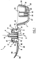
- FIG. 9 shows a dispensing head 50 according to a fifth embodiment of the invention, equipping the neck 51 with a container.
- the dispensing head 50 has a nozzle 52 to be fixed in the neck 51 and a capsule produced in one piece with the end piece 52, and constituted by the union of an annular body 53, of a cover pivoting 54 and a closing flap 55.
- the cover 54 and the flap 55 are connected by respective film hinges 56 and 57 to the annular body 53.
- the flap 55 includes a pin 58 intended to engage in a suitable recess of the cover 54 to maintain in place it as shown in Figure 9.
- the annular body 53 is connected by bridges of material scored 59 at the tip 52.
- the capsule After rupture of these bridges 59, the capsule can rotate around of the X axis of the nozzle.
- the end piece 52 has two skirts at the top concentric cylindrical 60 and 61 forming between them a groove annular in which is received a cylindrical skirt 63 integral of the cover 54.
- the inner skirt 61 is closed at its part upper and has an axial slot 64.
- the skirt 63 also has an axial slot 65, allowing when it is brought opposite the slot 64, to the product contained inside the container to leave it.
- a valve 66 is placed at the upper end of the skirt 63 to prevent dust or sand from getting inside reduce the risk of product leakage in the event of a fall of the container for example and still prevent drying of the product present on the internal walls of the neck 51 or contained in inside the skirt 63 or in the slots 64 and 65.
- the endpiece 52 is blocked in rotation on the neck 51 for example by engaging an external relief 67 of the neck 51 in a recess 68 of complementary shape of the end piece.
- the annular body 53 of the capsule is held axially on the neck by snapping into a groove 69 of the latter.
- the valve 66 came from molding in one piece with the cover 54. It is connected to the rest of the cover by a bridge material 70 allowing it to rise under the action of the product during distribution.
- Leclapet presents in top view as shown in Figure 10 a general shape in ⁇ and its edge free cleaning with the adjacent edge of the cover a gap g between 0.1 and 0.2 mm. This interstice allows the air intake.
- valve 66 is made of the same material as the cover but with a different color, by bi-injection molding of material. he can also be made by bi-injection in a material more flexible than that used to mold the rest of the cover. Finally, the valve can be made separately and attached and then fixed by any known means on the cover.
- the invention allows forms of distribution heads with undercuts and authorizes greater freedom in choosing the general aesthetics of the conditioning.
- the manufacturing of the dispensing head is made more easy thanks to the invention, in particular by the fact that it allows make the valve (s) without too much difficulty.
- the invention also makes it possible to reduce the possibilities of access to the interior of the capsule of foreign bodies such as sand.
- the material bridges 17, 17 ', 17' 'or 59 advantageously connecting the end piece and the capsule, able to hold the latter in a position in which it isolates the distribution channel from inside the container, avoid that during storage, before first use, the valve made of elastomer material is not contact with product and swelling of the valve material.
- the invention advantageously makes it possible to produce shapes with undercut for the distribution head with a minimum of material, the shell 24 of the capsule may be thin.
- Figures 1 to 10 correspond to examples of realizations comprising a nozzle to be fixed in a mouth of a container.
- the air intake can of course be carried out by a not completely sealed closure of the dispensing orifice product in the absence of product distribution, or during the return air, or by an air return valve not integral with the valve opening under the pressure of the product to be dispensed.
Landscapes
- Engineering & Computer Science (AREA)
- Mechanical Engineering (AREA)
- Closures For Containers (AREA)
- Containers And Packaging Bodies Having A Special Means To Remove Contents (AREA)
- Basic Packing Technique (AREA)
- Packaging Of Annular Or Rod-Shaped Articles, Wearing Apparel, Cassettes, Or The Like (AREA)
- Noodles (AREA)
- Manufacturing And Processing Devices For Dough (AREA)
Claims (14)
- Aufbewahrungs- und Spendevorrichtung für ein flüssiges, geliertes oder pastenartiges Produkt, die der Art nach einen Behälter zur Aufnahme des genannten Produkts und einen Spendekopf (1; 1'; 1'') aufweist, der mit einer Spendeöffnung (29) für das Produkt und einer Verschlußklappe (34; 34'; 34''; 40; 66) versehen ist, die dazu eingerichtet ist, die genannte Öffnung (29) in Abwesenheit eines Spendevorganges zu schließen und sie unter der Wirkung des Druckes des davor vorliegenden Produktes zu öffnen, dadurch gekennzeichnet, daß der Spendekopf (1; 1'; 1'') mindestens zwei Teile (7, 8; 7', 8'; 7'', 8''; 54, 55) aufweist, die aus einem einzigen Bauteil durch Abformen bzw. Formung zusammen mit einem dritten Teil (6; 6'; 6''; 53) gebildet sind und jeweils mit diesem letztgenannten durch eine Materialbrücke verbunden sind, die ein Scharnier (22, 23; 22', 23'; 22''; 23''; 56, 57) bildet, wobei das eine (8; 8'; 8''; 54) der beiden Teile, das mit dem dritten Teil verbunden ist, außerdem die genannte Verschlußklappe (34; 34'; 34''; 40; 66) trägt.
- Vorrichtung nach Anspruch 1, dadurch gekennzeichnet, daß die genannte Verschlußklappe (34; 34'; 34'') über dem Teil angebracht ist, das sie trägt.
- Vorrichtung nach irgendeinem der Ansprüche 1 und 2, dadurch gekennzeichnet, daß der Spendekopf eine Luftrückführklappe (41) bzw. ein Luftrückführventil aufweist.
- Vorrichtung nach Anspruch 3, dadurch gekennzeichnet, daß die Verschlußklappe (40), die sich zum Spenden des Produktes öffnet, und die Luftrückführungsklappe (41) aus einem einzigen Bauteil durch Aufformen von Elastomermaterial auf eines (8; 8'; 8'') der beiden Teile (7, 8; 7', 8'; 7'', 8'') gebildet sind, die jeweils mit einer Materialbrücke, die ein Scharnier bildet, mit dem genannten dritten Teil (6; 6'; 6'') verbunden sind.
- Vorrichtung nach Anspruch 1, dadurch gekennzeichnet, daß die genannte Verschlußklappe (66), zusammen mit dem Teil (54), das sie trägt, der Abformung eines einzigen Bauteils entstammt.
- Vorrichtung nach Anspruch 5, dadurch gekennzeichnet, daß die genannte Verschlußklappe (66) die allgemeine Form eines Ω aufweist, und daß ihr freier Rand eine Lücke, die zwischen 0,1 mm umd 0,2 mm liegt, zusammen mit dem gegenüberliegenden Rand freihält.
- Vorrichtung nach irgendeinem der Ansprüche 1 bis 6, dadurch gekennzeichnet, daß der Spendekopf einen Ansatz (4; 4'; 4''; 52) zur Befestigung in einer Ausgangsöffnung des Behälters oder auf einer Pumpe oder auf einem Ventil, mit der bzw. dem der Behälter versehen ist, aufweist, und daß die genannten Teile (7, 8; 7', 8'; 7'', 8''; 54, 55), die jeweils durch eine Materialbrücke, die ein Scharnier bildet, mit dem dritten Teil (6; 6'; 6''; 52, 53) verbunden sind, eine bewegliche Kapsel bilden, die mit der genannten Spendeöffnung versehen ist und mit der Möglichkeit einer Verlagerung bezüglich des Ansatzes angebracht ist, und zwar zwischen einer Öffnungslage, in der eine Verbindung zwischen der Spendeöffnung und dem Inneren des Behälters hergestellt ist, und einer Schließlage, in der die Kapsel mit dem Ansatz zusammenwirkt, um die genannte Spendeöffnung gegenüber dem Inneren des Behälters zu isolieren.
- Vorrichtung nach Anspruch 7, dadurch gekennzeichnet, daß der Ansatz (4; 4'; 4''; 53) aus einem einzigen Bauteil durch Abformen zusammen mit dem genannten dritten Teil hergestellt ist und mit diesem letztgenannten durch abtrennbare Materialbrücken (17; 17'; 17''; 59) verbunden ist.
- Vorrichtung nach Anspruch 8, dadurch gekennzeichnet, daß die genannten, abtrennbaren Materialbrücken während der ersten Benutzung der Vorrichtung zu zerbrechen sind und einen Originalitätsnachweis bilden.
- Vorrichtung nach Anspruch 8, dadurch gekennzeichnet, daß die genannten, abtrennbaren Materialbrücken während der Anbringung der Kapsel auf dem Behälter zerbrochen werden.
- Vorrichtung nach irgendeinem der Ansprüche 7 bis 10, dadurch gekennzeichnet, daß das genannte dritte Teil (6; 6'; 6'') eine kreisringförmige Gestalt aufweist.
- Vorrichtung nach irgendeinem der Ansprüche 1 bis 11, dadurch gekennzeichnet, daß der eine (7; 7'; 7''; 55) der beiden Teile, die durch eine Materialbrücke, die ein Scharnier bildet, mit dem dritten Teil verbunden sind, eine Sperrklappe bildet, die dazu eingerichtet ist, durch Zusammenwirkung von Formen den zweiten Teil (8; 8'; 8''; 54) auf dem dritten (6; 6'; 6''; 52, 53) zu halten.
- Vorrichtung nach Anspruch 12, dadurch gekennzeichnet, daß die Verschlußklappe einstückig mit dem Teil ausgebildet ist, der die genannte Sperrklappe bildet.
- Vorrichtung nach Anspruch 12, dadurch gekennzeichnet, daß die Verschlußklappe (66) fest bzw. einstückig mit dem Teil (54) verbunden ist, der durch die genannte Sperrklappe (55) auf dem dritten Teil (52, 53) gehalten ist.
Applications Claiming Priority (2)
| Application Number | Priority Date | Filing Date | Title |
|---|---|---|---|
| FR9511203A FR2739079B1 (fr) | 1995-09-25 | 1995-09-25 | Dispositif de conditionnement et de distribution |
| FR9511203 | 1995-09-25 |
Publications (2)
| Publication Number | Publication Date |
|---|---|
| EP0764590A1 EP0764590A1 (de) | 1997-03-26 |
| EP0764590B1 true EP0764590B1 (de) | 2000-01-12 |
Family
ID=9482873
Family Applications (1)
| Application Number | Title | Priority Date | Filing Date |
|---|---|---|---|
| EP96402021A Expired - Lifetime EP0764590B1 (de) | 1995-09-25 | 1996-09-24 | Aufbewahrungs- und Spendevorrichtung |
Country Status (8)
| Country | Link |
|---|---|
| US (1) | US5833123A (de) |
| EP (1) | EP0764590B1 (de) |
| JP (1) | JP3558317B2 (de) |
| CN (1) | CN1062229C (de) |
| CA (1) | CA2186396C (de) |
| DE (1) | DE69606127T2 (de) |
| ES (1) | ES2144709T3 (de) |
| FR (1) | FR2739079B1 (de) |
Cited By (1)
| Publication number | Priority date | Publication date | Assignee | Title |
|---|---|---|---|---|
| US7156266B2 (en) | 2002-06-28 | 2007-01-02 | L'oreal | Assembly for packaging and distribution of a product |
Families Citing this family (12)
| Publication number | Priority date | Publication date | Assignee | Title |
|---|---|---|---|---|
| FR2781133B1 (fr) * | 1998-07-15 | 2000-09-22 | Dior Christian Parfums | Dispositif d'ouverture et fermeture d'un flacon ou d'un tube relativement souple |
| FR2791329B1 (fr) * | 1999-03-23 | 2001-06-29 | Gerry Schiavon | Recipient distributeur de matiere pateuse ou liquide et son procede de fabrication |
| ITMI991312A1 (it) * | 1999-06-11 | 2000-12-11 | Capsol Spa Stampaggio Resine T | Tappo a chiusura automatica per l'erogazione di liquidi da contenitori deformabili |
| DE10027489A1 (de) * | 2000-06-02 | 2001-12-06 | Alpla Werke | Einem Gefäß zuordbarer Kippdüsenverschluss |
| US6655553B2 (en) | 2000-10-25 | 2003-12-02 | Seaquist Closures Foreign, Inc. | Dispensing closure with tamper-evident sleeve |
| DE102004021668A1 (de) * | 2004-05-03 | 2005-12-01 | Saint-Gobain Calmar Gmbh | Manuell betätigbarer Spender mit Schutzkappe |
| DE102004021670A1 (de) * | 2004-05-03 | 2005-12-01 | Saint-Gobain Calmar Gmbh | Manuell betätigbarer Spender mit Schutzkappe |
| FR2870215B1 (fr) * | 2004-05-17 | 2007-08-10 | Valois Sas | Capot pour tete de distribution de produit fluide. |
| DE602006005573D1 (de) * | 2005-10-28 | 2009-04-23 | Procter & Gamble | Ausgabeverschluss für Behälter |
| SG179076A1 (en) * | 2009-09-11 | 2012-04-27 | Kraft Foods Global Brands Llc | Containers and methods for dispensing multiple doses of a concentrated liquid, and shelf stable concentrated liquids |
| WO2012020360A1 (en) * | 2010-08-13 | 2012-02-16 | Koninklijke Philips Electronics N.V. | A water container and a machine for making beverages comprising said container |
| US11013248B2 (en) | 2012-05-25 | 2021-05-25 | Kraft Foods Group Brands Llc | Shelf stable, concentrated, liquid flavorings and methods of preparing beverages with the concentrated liquid flavorings |
Family Cites Families (9)
| Publication number | Priority date | Publication date | Assignee | Title |
|---|---|---|---|---|
| FR2650562B1 (fr) * | 1989-07-25 | 1991-11-29 | Oreal | Ensemble de distribution d'un ou plusieurs produit(s) sous forme de creme, de liquide ou de poudre, notamment de produits cosmetiques |
| FR2660877B1 (fr) * | 1990-04-13 | 1992-07-31 | Oreal | Ensemble de distribution d'au moins un produit liquide ou sous forme de creme. |
| FR2674024B1 (fr) * | 1991-03-11 | 1994-03-11 | Daniel Crosnier | Dispositif doseur adaptable sur des contenants divers. |
| US5662245A (en) * | 1992-12-18 | 1997-09-02 | Schmalbach-Lubeca Ag | Container with integrally molded closure/tamper indicator |
| US5310111A (en) * | 1993-03-19 | 1994-05-10 | Johnson Service Company | Pneumatic controller |
| FR2704458B1 (fr) * | 1993-04-28 | 1995-07-21 | Oreal | Ensemble de distribution de produit. |
| FR2711620B1 (fr) * | 1993-10-21 | 1995-12-22 | Oreal | Ensemble de distribution équipé d'un organe de fermeture unidirectionnel. |
| DE9411622U1 (de) * | 1994-07-18 | 1994-11-17 | Coster Tecnologie Speciali Spa | Vorrichtung zum dosierten Austrag eines fließfähigen Mediums |
| US5655685A (en) * | 1995-05-31 | 1997-08-12 | Clayton Corporation | Closure assembly for a container having a tamper-evident pouring spout closure member |
-
1995
- 1995-09-25 FR FR9511203A patent/FR2739079B1/fr not_active Expired - Fee Related
-
1996
- 1996-09-16 US US08/716,647 patent/US5833123A/en not_active Expired - Fee Related
- 1996-09-24 DE DE69606127T patent/DE69606127T2/de not_active Expired - Fee Related
- 1996-09-24 ES ES96402021T patent/ES2144709T3/es not_active Expired - Lifetime
- 1996-09-24 JP JP25147596A patent/JP3558317B2/ja not_active Expired - Fee Related
- 1996-09-24 CA CA002186396A patent/CA2186396C/fr not_active Expired - Fee Related
- 1996-09-24 EP EP96402021A patent/EP0764590B1/de not_active Expired - Lifetime
- 1996-09-25 CN CN96122072A patent/CN1062229C/zh not_active Expired - Fee Related
Cited By (1)
| Publication number | Priority date | Publication date | Assignee | Title |
|---|---|---|---|---|
| US7156266B2 (en) | 2002-06-28 | 2007-01-02 | L'oreal | Assembly for packaging and distribution of a product |
Also Published As
| Publication number | Publication date |
|---|---|
| EP0764590A1 (de) | 1997-03-26 |
| FR2739079A1 (fr) | 1997-03-28 |
| JP3558317B2 (ja) | 2004-08-25 |
| US5833123A (en) | 1998-11-10 |
| DE69606127D1 (de) | 2000-02-17 |
| CA2186396C (fr) | 2003-02-25 |
| FR2739079B1 (fr) | 1997-11-14 |
| CN1154330A (zh) | 1997-07-16 |
| CA2186396A1 (fr) | 1997-03-26 |
| DE69606127T2 (de) | 2000-09-28 |
| ES2144709T3 (es) | 2000-06-16 |
| CN1062229C (zh) | 2001-02-21 |
| JPH09118353A (ja) | 1997-05-06 |
Similar Documents
| Publication | Publication Date | Title |
|---|---|---|
| EP0342109B1 (de) | Verschlusseinrichtung mit drehbarer Manschette für Flakons und ähnliche Behälter | |
| EP0758615B1 (de) | Aufnahme- und Ausgabevorrichtung | |
| EP1521710B1 (de) | Verschlussvorrichtung mit einem in schliessposition geformten scharnierdeckel | |
| EP0410858B1 (de) | Abgabevorrichtung für wenigstens ein flüssiges Produkt, insbesondere kosmetischer oder pharmazeutischer Art | |
| EP0764590B1 (de) | Aufbewahrungs- und Spendevorrichtung | |
| EP0714836B1 (de) | Betätigungsvorrichtung für des Abgabeventil eines Aerosolbehälters | |
| EP0649795A2 (de) | Ausgabevorrichtung, versehen mit einem Rückschlagventil | |
| EP1254058B1 (de) | Behälterverschluss | |
| FR2688197A1 (fr) | Fermeture distributrice a collier de basculement. | |
| WO1998008746A1 (fr) | Capsule de distribution a etancheite amelioree | |
| FR2647088A1 (fr) | Ensemble verseur et capsule de bouchage avec charniere a ressort | |
| EP0807064B1 (de) | abgabeflasche | |
| FR2814150A1 (fr) | Dispositif pour la fixation reversible d'un recipient sur un support et recipient equipe d'un tel dispositif | |
| FR2736329A1 (fr) | Cape de bouchage munie d'un dispositif de degazage, procede de fabrication d'une telle cape et dispositif pour la mise en oeuvre de ce procede | |
| EP0497961B1 (de) | Abgabevorrichtung mit automatischem verschluss für flüssigkeit oder paste enthaltenden behälter | |
| EP1472007B1 (de) | Spender für fliessfähige medien mit einer pumpe | |
| FR2729924A1 (fr) | Flacon de distribution de produit | |
| WO2007077361A2 (fr) | Buse de distribution de produit fluide, dispositif de distribution comprenant un telle buse et procede de fabrication | |
| EP0755880B1 (de) | Abgabevorrichtung für ein unter Druck stehendes Produkt und mit einer solchen Vorrichtung versehener Behälter | |
| EP0852205B1 (de) | Verschlusskappe für einen mit einem Befestigungsflansch versehenen Behälter | |
| EP0825128B1 (de) | Element zur Befestigung einer Abgabevorrichtung an einem Behälterhals | |
| FR2516899A1 (fr) | Dispositif pour prelever des substances pateuses dans des recipients remplis avec un gaz propulseur | |
| FR2742734A1 (fr) | Perfectionnement a un recipient manipulable en matiere plastique | |
| FR2769005A1 (fr) | Capsule service pour recipient distributeur | |
| FR2608563A1 (fr) | Recipient distributeur a compte-gouttes |
Legal Events
| Date | Code | Title | Description |
|---|---|---|---|
| PUAI | Public reference made under article 153(3) epc to a published international application that has entered the european phase |
Free format text: ORIGINAL CODE: 0009012 |
|
| AK | Designated contracting states |
Kind code of ref document: A1 Designated state(s): DE ES FR GB IT |
|
| 17P | Request for examination filed |
Effective date: 19970426 |
|
| GRAG | Despatch of communication of intention to grant |
Free format text: ORIGINAL CODE: EPIDOS AGRA |
|
| 17Q | First examination report despatched |
Effective date: 19990331 |
|
| GRAG | Despatch of communication of intention to grant |
Free format text: ORIGINAL CODE: EPIDOS AGRA |
|
| GRAH | Despatch of communication of intention to grant a patent |
Free format text: ORIGINAL CODE: EPIDOS IGRA |
|
| GRAH | Despatch of communication of intention to grant a patent |
Free format text: ORIGINAL CODE: EPIDOS IGRA |
|
| GRAA | (expected) grant |
Free format text: ORIGINAL CODE: 0009210 |
|
| AK | Designated contracting states |
Kind code of ref document: B1 Designated state(s): DE ES FR GB IT |
|
| REF | Corresponds to: |
Ref document number: 69606127 Country of ref document: DE Date of ref document: 20000217 |
|
| ITF | It: translation for a ep patent filed |
Owner name: MODIANO & ASSOCIATI S.R.L. |
|
| GBT | Gb: translation of ep patent filed (gb section 77(6)(a)/1977) |
Effective date: 20000329 |
|
| REG | Reference to a national code |
Ref country code: ES Ref legal event code: FG2A Ref document number: 2144709 Country of ref document: ES Kind code of ref document: T3 |
|
| PLBE | No opposition filed within time limit |
Free format text: ORIGINAL CODE: 0009261 |
|
| STAA | Information on the status of an ep patent application or granted ep patent |
Free format text: STATUS: NO OPPOSITION FILED WITHIN TIME LIMIT |
|
| 26N | No opposition filed | ||
| REG | Reference to a national code |
Ref country code: GB Ref legal event code: IF02 |
|
| PGFP | Annual fee paid to national office [announced via postgrant information from national office to epo] |
Ref country code: DE Payment date: 20070920 Year of fee payment: 12 |
|
| PGFP | Annual fee paid to national office [announced via postgrant information from national office to epo] |
Ref country code: GB Payment date: 20070919 Year of fee payment: 12 |
|
| PGFP | Annual fee paid to national office [announced via postgrant information from national office to epo] |
Ref country code: IT Payment date: 20070926 Year of fee payment: 12 Ref country code: ES Payment date: 20071024 Year of fee payment: 12 |
|
| PGFP | Annual fee paid to national office [announced via postgrant information from national office to epo] |
Ref country code: FR Payment date: 20070914 Year of fee payment: 12 |
|
| GBPC | Gb: european patent ceased through non-payment of renewal fee |
Effective date: 20080924 |
|
| REG | Reference to a national code |
Ref country code: FR Ref legal event code: ST Effective date: 20090529 |
|
| PG25 | Lapsed in a contracting state [announced via postgrant information from national office to epo] |
Ref country code: IT Free format text: LAPSE BECAUSE OF NON-PAYMENT OF DUE FEES Effective date: 20080924 Ref country code: DE Free format text: LAPSE BECAUSE OF NON-PAYMENT OF DUE FEES Effective date: 20090401 |
|
| PG25 | Lapsed in a contracting state [announced via postgrant information from national office to epo] |
Ref country code: FR Free format text: LAPSE BECAUSE OF NON-PAYMENT OF DUE FEES Effective date: 20080930 |
|
| REG | Reference to a national code |
Ref country code: ES Ref legal event code: FD2A Effective date: 20080925 |
|
| PG25 | Lapsed in a contracting state [announced via postgrant information from national office to epo] |
Ref country code: GB Free format text: LAPSE BECAUSE OF NON-PAYMENT OF DUE FEES Effective date: 20080924 |
|
| PG25 | Lapsed in a contracting state [announced via postgrant information from national office to epo] |
Ref country code: ES Free format text: LAPSE BECAUSE OF NON-PAYMENT OF DUE FEES Effective date: 20080925 |