EP0764590B1 - Conditioning and dispensing device - Google Patents
Conditioning and dispensing device Download PDFInfo
- Publication number
- EP0764590B1 EP0764590B1 EP96402021A EP96402021A EP0764590B1 EP 0764590 B1 EP0764590 B1 EP 0764590B1 EP 96402021 A EP96402021 A EP 96402021A EP 96402021 A EP96402021 A EP 96402021A EP 0764590 B1 EP0764590 B1 EP 0764590B1
- Authority
- EP
- European Patent Office
- Prior art keywords
- valve
- container
- dispensing
- product
- orifice
- Prior art date
- Legal status (The legal status is an assumption and is not a legal conclusion. Google has not performed a legal analysis and makes no representation as to the accuracy of the status listed.)
- Expired - Lifetime
Links
Images


Classifications
-
- B—PERFORMING OPERATIONS; TRANSPORTING
- B65—CONVEYING; PACKING; STORING; HANDLING THIN OR FILAMENTARY MATERIAL
- B65D—CONTAINERS FOR STORAGE OR TRANSPORT OF ARTICLES OR MATERIALS, e.g. BAGS, BARRELS, BOTTLES, BOXES, CANS, CARTONS, CRATES, DRUMS, JARS, TANKS, HOPPERS, FORWARDING CONTAINERS; ACCESSORIES, CLOSURES, OR FITTINGS THEREFOR; PACKAGING ELEMENTS; PACKAGES
- B65D47/00—Closures with filling and discharging, or with discharging, devices
- B65D47/04—Closures with discharging devices other than pumps
- B65D47/20—Closures with discharging devices other than pumps comprising hand-operated members for controlling discharge
- B65D47/2018—Closures with discharging devices other than pumps comprising hand-operated members for controlling discharge comprising a valve or like element which is opened or closed by deformation of the container or closure
-
- B—PERFORMING OPERATIONS; TRANSPORTING
- B65—CONVEYING; PACKING; STORING; HANDLING THIN OR FILAMENTARY MATERIAL
- B65D—CONTAINERS FOR STORAGE OR TRANSPORT OF ARTICLES OR MATERIALS, e.g. BAGS, BARRELS, BOTTLES, BOXES, CANS, CARTONS, CRATES, DRUMS, JARS, TANKS, HOPPERS, FORWARDING CONTAINERS; ACCESSORIES, CLOSURES, OR FITTINGS THEREFOR; PACKAGING ELEMENTS; PACKAGES
- B65D47/00—Closures with filling and discharging, or with discharging, devices
- B65D47/04—Closures with discharging devices other than pumps
- B65D47/20—Closures with discharging devices other than pumps comprising hand-operated members for controlling discharge
- B65D47/26—Closures with discharging devices other than pumps comprising hand-operated members for controlling discharge with slide valves, i.e. valves that open and close a passageway by sliding over a port, e.g. formed with slidable spouts
- B65D47/261—Closures with discharging devices other than pumps comprising hand-operated members for controlling discharge with slide valves, i.e. valves that open and close a passageway by sliding over a port, e.g. formed with slidable spouts having a rotational or helicoidal movement
- B65D47/263—Closures with discharging devices other than pumps comprising hand-operated members for controlling discharge with slide valves, i.e. valves that open and close a passageway by sliding over a port, e.g. formed with slidable spouts having a rotational or helicoidal movement between tubular parts
Landscapes
- Engineering & Computer Science (AREA)
- Mechanical Engineering (AREA)
- Closures For Containers (AREA)
- Containers And Packaging Bodies Having A Special Means To Remove Contents (AREA)
- Manufacturing And Processing Devices For Dough (AREA)
- Packaging Of Annular Or Rod-Shaped Articles, Wearing Apparel, Cassettes, Or The Like (AREA)
- Noodles (AREA)
- Basic Packing Technique (AREA)
Description
La présente invention concerne un dispositif de conditionnement et de distribution d'un produit liquide, gélifié ou pâteux, du type comprenant un récipient pour contenir ledit produit et une tête de distribution pourvue d'un orifice de distribution du produit et d'un clapet, apte à fermer ledit orifice en l'absence de distribution de produit et apte à s'ouvrir sous l'effet de la pression du produit en amont lors de la distribution.The present invention relates to a device for packaging and distribution of a liquid, gelled or pasty, of the type comprising a container for containing said product and a dispensing head provided with a dispensing orifice product and a valve, capable of closing said orifice in the absence of product distribution and able to open under the effect of product pressure upstream during distribution.
Un tel dispositif est connu par EP-A-0 452 196 de la société déposante, ou la tête de distribution se compose de trois élements distincts.Such a device is known from EP-A-0 452 196 from the company depositor, or the distribution head consists of three elements separate.
L'invention a pour objet d'améliorer encore un tel dispositif.The object of the invention is to further improve such a device.
Elle y parvient par le fait que la tête de distribution comporte au moins deux parties qui sont réalisées d'un seul tenant par moulage avec une troisième partie et sont reliées chacune à cette dernière par un pont de matière formant charnière, l'une des deux parties reliées à la troisième partie portant en outre ledit clapet.It achieves this by the fact that the distribution head has at least two parts which are made in one piece by molding with a third part and are each connected to the latter by a bridge of material forming a hinge, one of the two parts connected to the third part further carrying said valve.
Dans une réalisation particulière de l'invention, la tête de distribution comporte un embout à fixer dans une embouchure du récipient ou sur une pompe ou sur une valve équipant le récipient, et lesdites parties reliées chacune par un pont de matière formant charnière à la troisième partie constituent une capsule mobile pourvue dudit orifice de distribution et montée avec une possibilité de déplacement par rapport à l'embout entre une position d'ouverture dans laquelle une communication est établie entre l'orifice de distribution et l'intérieur du récipient et une position de fermeture dans laquelle la capsule coopère avec l'embout pour isoler ledit orifice de distribution de l'intérieur du récipient.In a particular embodiment of the invention, the head of distribution includes a nozzle to be fixed in a mouth of the container or on a pump or on a valve fitted to the container, and said parts each connected by a bridge of material forming hinge to the third part constitute a movable capsule provided with said dispensing orifice and mounted with a possibility displacement relative to the endpiece between an open position in which communication is established between the orifice of distribution and the interior of the container and a position of closure in which the capsule cooperates with the end piece to isolate said dispensing orifice inside the container.
Avantageusement, l'embout est réalisé d'un seul tenant par moulage avec ladite troisième partie en étant relié à cette dernière par des ponts de matière sécables. Dans un mode de réalisation de l'invention, les ponts de matière sécables sont à rompre lors de la première utilisation du dispositif et constituent un témoin d'inviolabilité. En variante, les ponts de matière sécables peuvent être rompus lors du montage de la capsule sur le récipient. Advantageously, the end piece is made in one piece by molding with said third part while being connected to the latter by bridges of breakable material. In one embodiment of the invention, the bridges of breakable material are to be broken during the first use of the device and constitute a witness inviolability. Alternatively, the bridges of breakable material can be broken when mounting the capsule on the container.
Dans une réalisation particulière de l'invention, ledit clapet est réalisé par surmoulage en matériau élastomère sur l'une desdites parties.In a particular embodiment of the invention, said valve is produced by overmolding of elastomeric material on one of said parties.
Dans une autre réalisation, le clapet est venu de moulage d'un seul tenant avec l'une des parties.In another embodiment, the valve came from molding in one piece with one of the parties.
Dans une réalisation particulière de l'invention, la capsule est réalisée par moulage d'une partie formant corps annulaire, reliée par au moins un pont de matière à l'embout, et de deux parties pivotantes reliées chacune par un pont de matière formant charnière audit corps annulaire, le clapet précité étant solidaire de l'une desdites parties, l'une des deux parties pivotantes constituant un rabat de fermeture apte à retenir par coopération de formes l'autre partie pivotante sur ledit corps annulaire après pivotement.In a particular embodiment of the invention, the capsule is produced by molding a part forming an annular body, connected by at least one material bridge to the end piece, and two pivoting parts each connected by a bridge of material forming hinge to said annular body, the aforementioned valve being integral of one of said parts, one of the two pivoting parts constituting a closure flap capable of retaining by cooperation of forms the other pivoting part on said annular body after pivoting.
Dans une réalisation particulière de l'invention, le clapet est solidaire de la partie pivotante formant rabat de fermeture.In a particular embodiment of the invention, the valve is integral with the pivoting part forming a closing flap.
Dans une autre réalisation particulière de l'invention, le clapet est solidaire de la partie qui est retenue sur ladite troisième partie par le rabat de fermeture.In another particular embodiment of the invention, the valve is integral with the part which is retained on said third part by the closing flap.
Dans une réalisation particulière de l'invention, la partie de la tête de distribution qui porte le clapet s'ouvrant pour la sortie du produit comporte en outre un clapet de reprise d'air.In a particular embodiment of the invention, the part of the dispensing head which carries the valve opening for the product outlet further includes an air return valve.
Avantageusement, le clapet s'ouvrant pour la distribution de produit et le clapet de reprise d'air sont réalisés d'un seul tenant par surmoulage de matière élastomère.Advantageously, the valve opening for the distribution of product and the air return valve are made in one piece by overmolding of elastomeric material.
Dans le mode de réalisation particulier évoqué plus haut dans lequel le clapet est venu de moulage avec la partie qui le porte, le clapet présente de préférence une forme en Ω et son bord libre ménage avec le bord en regard un interstice compris de préférence entre 0,1 et 0,2 mm.In the particular embodiment mentioned above in which the valve came from molding with the part that carries it, the valve preferably has an Ω shape and its free edge cleaning with the facing edge a gap preferably understood between 0.1 and 0.2 mm.
D'autres caractéristiques et avantages de la présente invention apparaítront à la lecture de la description détaillée qui va suivre, d'exemples de réalisation non limitatifs de l'invention, et à l'examen du dessin annexé sur lequel :
- la figure 1 est une vue en coupe axiale, schématique, d'un ensemble formant tête de distribution, constitué d'un embout et d'une capsule, réalisés d'un seul tenant par moulage en matière plastique,
- les figures 2 et 3 illustrent différentes étapes du montage de la tête de distribution représentée sur la figure 1 sur un col d'un récipient,
- la figure 4 est une vue en coupe axiale, schématique, d'une tête de distribution selon un deuxième exemple de réalisation de l'invention,
- la figure 5 est une vue partielle, en élévation, d'un récipient équipé de la tête de distribution représentée sur la figure 4,
- la figure 6 est une vue en coupe axiale, schématique, d'une tête de distribution conforme à un troisième exemple de réalisation de l'invention,
- la figure 7 est une vue partielle, en élévation, d'un récipient équipé de la tête de distribution représentée sur la figure 6,
- la figure 8 est une vue partielle, en coupe, d'une tête de distribution conforme à un quatrième exemple de réalisation de l'invention,
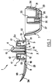
- la figure 9 est une vue en coupe axiale, schématique d'une tête de distribution selon un cinquième exemple de réalisation de l'invention, et
- la figure 10 est une vue partielle, de dessus, selon la flèche X de la figure 9.
- FIG. 1 is a schematic view in axial section of an assembly forming a dispensing head, consisting of a nozzle and a capsule, produced in one piece by plastic molding,
- FIGS. 2 and 3 illustrate different stages in the mounting of the dispensing head shown in FIG. 1 on a neck of a container,
- FIG. 4 is a schematic view in axial section of a dispensing head according to a second embodiment of the invention,
- FIG. 5 is a partial view, in elevation, of a container fitted with the dispensing head shown in FIG. 4,
- FIG. 6 is a schematic view in axial section of a dispensing head according to a third embodiment of the invention,
- FIG. 7 is a partial view, in elevation, of a container equipped with the dispensing head shown in FIG. 6,
- FIG. 8 is a partial view, in section, of a dispensing head according to a fourth embodiment of the invention,
- FIG. 9 is a diagrammatic view in axial section of a dispensing head according to a fifth embodiment of the invention, and
- FIG. 10 is a partial view from above, according to arrow X in FIG. 9.
On a représenté sur les figures 1 à 3 une tête de
distribution 1 conforme à un premier exemple de réalisation de
l'invention, destinée à être montée sur le col 2 d'un récipient 3
connu en lui-même et réalisé par exemple par une technique
d'injection-soufflage. La tête de distribution 1 est constituée d'un
embout 4, à fixer dans le col 2 et d'une capsule 5 réalisée d'un
seul tenant avec l'embout 4 et formée par la réunion d'un corps
annulaire 6, d'un couvercle pivotant 7 et d'un rabat pivotant 8.There is shown in Figures 1 to 3 a head of
L'embout 4 comporte deux jupes tubulaires 9, 10 coaxiales
d'axe X, de section transversale circulaire, réunies en 11 à leur
extrémité inférieure. La jupe tubulaire radialement la plus externe,
référencée 10, se prolonge radialement vers l'extérieur à son
extrémité supérieure pour former un rebord annulaire 12 recourbé
vers le bas, conformé pour s'engager sur la tranche d'extrémité
supérieure du col 2. La jupe tubulaire 9 radialement la plus interne
se prolonge axialement à son extrémité supérieure au-delà du rebord
annulaire 12 comme représenté sur la figure 1. Le rebord annulaire
12 est évidé sur un secteur angulaire limité de sa périphérie pour
former une découpe 13 destinée à coopérer avec un ergot 14 de forme
complémentaire formant saillie sur la surface radialement externe du
col 2 pour immobiliser en rotation l'embout 4 sur le col 2. La jupe
tubulaire 9 est ajourée à partir de sa tranche d'extrémité
supérieure, sur un secteur angulaire limité de sa périphérie, pour
former une ouverture latérale 15 pour le passage de produit comme
cela sera précisé dans la suite.The
Le diamètre externe de la jupe tubulaire 10 est choisi de
manière à ce que l'embout 4 s'ajuste à force de façon étanche dans
le col 2. La jupe tubulaire 9 délimite intérieurement un canal 16
pour le passage de produit depuis l'intérieur du récipient 3.
L'embout 4, une fois en place dans le col 2, diminue la section de
passage offerte à l'écoulement de produit quittant le récipient 3
par le col 2.The external diameter of the
Le corps annulaire 6 présente une paroi 6a de forme
générale tubulaire, de section transversale circulaire centrée sur
l'axe X, sur laquelle sont formées au moins deux languettes
flexibles de retenue 18 diamétralement opposées, munies à leur
extrémité inférieure de bossages 19 formant radialement saillie sur
la surface interne de la paroi 6a, destinés à s'encliqueter sur un
bourrelet annulaire 20 formant radialement saillie sur la surface
externe du col 2 comme représenté sur les figures 2 et 3. La paroi
6a est pourvue à son extrémité inférieure d'une collerette 21
formant radialement saillie sur sa surface externe. Le couvercle
pivotant 7 et le rabat pivotant 8 sont reliés à la collerette 21, en
des emplacements diamétralement opposés, par l'intermédiaire de
ponts de matière formant charnières respectivement référencés 22 et
23.The
Des ponts de matière 17 relient la surface radialement la
plus externe du rebord annulaire 12 de l'embout 4 à la surface
radialement interne du corps annulaire 6 au voisinage de sa tranche
d'extrémité supérieure.
Le couvercle pivotant 7 présente une coque externe 24 ayant
la forme générale d'un dôme aplati en 27 à son sommet et comporte
intérieurement deux tubulures coaxiales 25 et 26 se raccordant sur
la face interne de la paroi aplatie 27 de la coque 24. Un canal de
passage de produit est formé dans l'épaisseur de la paroi 27,
débouchant à une extrémité dans l'espace annulaire 30 formé entre
les tubulures 25 et 26 et à l'autre extrémité sur un orifice de
distribution 29 situé sur la paroi latérale de la coque 24. Cette
dernière est évidée en 31 sensiblement à l'aplomb de l'orifice de
distribution 29 pour la fixation du rabat pivotant 8 sur le
couvercle pivotant 7. Le diamètre interne de la tubulure 25 ainsi
que l'épaisseur de sa paroi sont choisis de manière à ce que lorsque
le couvercle pivotant 7 est rabattu sur le corps annulaire 6, la
tubulure 25 s'engage dans la gorge annulaire 32 formée entre les
jupes tubulaires 9 et 10 et s'ajuste de façon étanche sur la surface
radialement interne de la jupe tubulaire 10. De façon plus générale,
la tubulure 25 et la jupe tubulaire 9 sont conformées de manière à
permettre, compte-tenu de la géométrie du pont de matière 22, le
montage de l'une sur l'autre. Le diamètre externe de la tubulure 26
est choisi de manière à ce que cette dernière se loge à l'intérieur
de la jupe tubulaire 9 lorsque le couvercle pivotant 7 est en place
sur le corps annulaire 6. Le pont de matière 22 est réalisé avec une
conformation en V et sa longueur est choisie de manière à conférer
au couvercle pivotant 7 la mobilité nécessaire pour engager la
tubulure 25 sur la jupe tubulaire 9.The
Le rabat pivotant 8 est conformé pour se fixer sur la surface
externe latérale du couvercle pivotant 7 et présente un picot 33
apte à s'engager dans l'évidement 31, pour retenir le rabat pivotant
8 appliqué sur le couvercle pivotant 7. Une lame élastique, effilée,
est surmoulée sur la paroi rigide constituant le reste du rabat
pivotant 8 pour former un clapet 34 recouvrant au repos l'orifice de
distribution 29.The
Le picot 13 est réalisé en matière plastique rigide. En
variante il peut être réalisé en matière plastique souple auquel cas
il est avantageusement surmoulé avec le clapet (variante non
représentée).The
Selon une caractéristique avantageuse de l'invention, embout
4 et capsule 5 sont réalisés d'un seul tenant en matière plastique,
ce qui simplifie la manutention de la tête de distribution 1 ainsi
que sa mise en place sur le récipient 3. Après moulage de l'embout 4
et de la capsule 5 dans la configuration représentée sur la figure
1, c'est-à-dire avec le rabat pivotant 8 s'étendant sensiblement
perpendiculairement à l'axe X et les axes des tubulures 25 et 26
orientés sensiblement parallèlement à l'axe X, le corps annulaire 6
est encliqueté sur le col 2 du récipient (après remplissage de ce
dernier) puis le couvercle 7 et le rabat 8 sont pivotés vers le
corps annulaire 6 respectivement de 180° et de 90° environ et
solidarisés par insertion à force du picot 33 dans l'évidement 31.
L'immobilisation en rotation de l'embout 4 par rapport au col 2 est
garantie grâce à la coopération de formes entre l'ergot 14 et la
découpe 13.According to an advantageous characteristic of the invention,
Après assemblage de la capsule 5, comme représenté sur la
figure 3, le canal 28 se situe à l'opposé de l'ouverture latérale 15
et il est isolé de cette dernière par la jupe tubulaire 9.After assembly of the
La tête de distribution 1 est ainsi fermée, le clapet 34
isolé du produit, et tout départ de produit empêché.The dispensing
Lors de la première utilisation du dispositif, l'utilisateur
doit entraíner en rotation la capsule 5 autour de l'axe X pour
amener l'ouverture latérale 15 en regard du canal 28.When using the device for the first time, the user
must rotate the
Lors de cette rotation, les ponts de matière 17 se rompent, ce qui avertit l'utilisateur que le dispositif n'a pas été utilisé précédemment.During this rotation, the material bridges 17 break, which alerts the user that the device has not been used previously.
Le départ de produit peut être provoqué par écrasement du
récipient 3 lorsque ce dernier est réalisé dans une matière
plastique souple ou par tout autre dispositif de mise sous pression
du produit à l'intérieur du récipient. Le clapet 34 s'écarte de son
siège sur le couvercle pivotant 7 sous l'effet de la pression du
produit en amont dans l'orifice de distribution 29.Product departure can be caused by overwriting the
Après distribution d'une dose de produit, le clapet 34
reprend sa position de repos dans laquelle il obture l'orifice de
distribution 29 grâce à son élasticité propre, le retour du clapet
dans sa position de repos étant facilité le cas échéant par l'effet
de succion accompagnant le retour du récipient 3 dans sa
conformation initiale.After dispensing a dose of product, the
Il est à noter que les dimensions initiales du clapet
surmoulé peuvent être telles qu'un jeu est ménagé entre le clapet et
son siège sur le couvercle 7 pour tenir compte du gonflement de la
matière du clapet au contact du produit lors de l'utilisation.It should be noted that the initial dimensions of the valve
molded can be such that a clearance is made between the valve and
its seat on the
On a représenté sur les figures 4 à 7 deux variantes de réalisation d'un dispositif selon l'invention pour illustrer la possibilité de réaliser grâce à l'invention des formes en contre-dépouille pour la tête de distribution.There are shown in Figures 4 to 7 two variants of realization of a device according to the invention to illustrate the possibility of realizing thanks to the invention in undercut for the distribution head.
On attribuera dans la suite de la description des numéros de référence identiques, simplement affectés d'un ' , pour désigner des éléments identiques ou fonctionnellement analogues à ceux de la réalisation précédente, et qui pourront par conséquent ne pas être décrits à nouveau dans le détail.In the following description, numbers will be assigned identical references, simply assigned a ', to designate elements identical or functionally analogous to those of the previous achievement, and which may therefore not be described again in detail.
La tête de distribution 1' représentée sur les figures 4 et 5
diffère essentiellement de la tête de distribution 1 décrite
précédemment par la géométrie du corps annulaire 6' et par
l'agencement de l'embout 4' et du couvercle pivotant 7' permettant
d'isoler ou de mettre en communication le canal 28' avec l'intérieur
du récipient 3'. Le corps annulaire 6' comporte une paroi tubulaire
6a' sur laquelle se raccordent les ponts de matière 17' reliant
l'embout 4' à la capsule 5'.The dispensing head 1 'shown in FIGS. 4 and 5 differs essentially from the dispensing
La paroi 6a' est prolongée radialement vers l'extérieur à
partir de son extrémité inférieure vers le haut par une paroi 6b'
présentant une forme générale évasée convexe vers l'extérieur.The
Le couvercle pivotant 7' et le rabat pivotant 8' sont reliés
au corps annulaire 6' par des ponts de matière formant charnières
22' et 23' se raccordant respectivement à la tranche d'extrémité
supérieure de la paroi 6b' en des emplacements diamétralement
opposés. La paroi 6b' forme avec le couvercle pivotant 7',
lorsque ce dernier est rabattu sur le corps annulaire 6', une tête
de distribution en forme de boule comme représenté sur la figure 5.The pivoting cover 7 'and the pivoting flap 8' are connected to the annular body 6 'by bridges of material forming hinges 22' and 23 'respectively connecting to the upper end edge of the
L'embout 4' diffère de l'embout 4 précédemment décrit par
l'absence de jupe tubulaire 9 et par le fait que la jupe tubulaire
10' est traversée latéralement par un perçage formant une ouverture
15' pour le passage du produit depuis l'intérieur du récipient 3'
vers le canal de distribution 28'.The tip 4 'differs from the
Bien entendu, la surface intérieure du col du récipient 3' dans laquelle est insérée la jupe tubulaire 10' est conformée de manière à permettre une arrivée de produit depuis l'intérieur du récipient 3' jusqu'à l'ouverture 15'.Of course, the inner surface of the neck of the container 3 ' in which the tubular skirt 10 'is inserted is shaped so as to allow product to arrive from inside the container 3 'until opening 15'.
Le couvercle pivotant 7' diffère principalement du couvercle
7 précédemment décrit par le fait que la tubulure 25' est ajourée
latéralement à partir de sa tranche d'extrémité pour former une
ouverture 35' de passage de produit entre l'ouverture latérale 15'
et l'intérieur 36' de la tubulure 25'. Lorsque le couvercle 7' est
rabattu sur le corps annulaire 6', la tubulure 25' s'ajuste de façon
étanche à l'intérieur de la jupe tubulaire 10'.The pivoting cover 7 'differs mainly from the
On a représenté sur les figures 6 et 7 une tête de
distribution 1'' conforme à une deuxième variante de réalisation de
la tête de distribution 1 précédemment décrite.Figures 6 and 7 show a head of
1 '' distribution according to a second alternative embodiment of
the dispensing
On a utilisé des numéros de référence identiques simplement affectés d'un '' pour désigner des éléments identiques ou fonctionnellement analogues à ceux précédemment décrits en référence aux figures 1 à 3.We used identical reference numbers simply marked with '' to designate identical elements or functionally analogous to those previously described with reference in Figures 1 to 3.
La tête de distribution 1'' diffère principalement de la tête
de distribution 1' par la géométrie du corps annulaire 6''. Ce
dernier présente une paroi 6a'' concave vers l'extérieur formant,
après assemblage de la tête de distribution 1'' sur le récipient 3'',
une gorge annulaire 37'' comme représenté sur la figure 7. L'embout
4'', le couvercle pivotant 7'' et le rabat pivotant 8'' sont identiques
à ceux précédemment décrits en référence à la figure 4.The distribution head 1 '' differs mainly from the distribution head 1 'by the geometry of the annular body 6''. The latter has a
On a représenté sur la figure 8 un exemple de réalisation
dans lequel deux clapets 40, 41 sont réalisés pour s'ouvrir
respectivement lors de la distribution du produit et après la
distribution pour la reprise d'air dans le récipient.There is shown in Figure 8 an embodiment
in which two
Dans l'exemple décrit, les clapets 40 et 41 sont réalisés
d'un seul tenant par surmoulage de matière plastique élastomère sur
un rabat 42 représenté partiellement et relié par un pont de matière
formant charnière au reste de la tête de distribution, à l'instar
des rabats 8, 8' et 8'' précédemment décrits. L'opération de
surmoulage est facilitée dans la mesure où la partie qui porte les
clapets, c'est-à-dire le rabat 42 s'étend à l'écart du reste de la
tête de distribution lors de la fabrication de celle-ci, en étant
reliée par le pont de matière 23. Elle est ainsi plus facilement
accessible pour des opérations de surmoulage de matière plastique.
Le rabat 42 comporte une ouverture 43 associée au clapet 41. Ce
dernier est conformé pour s'engager au repos à l'intérieur de
l'ouverture 43 et s'appliquer sur la surface interne du rabat 42
bordant l'ouverture 43.In the example described, the
Le rabat 42 comporte sur sa face interne une paroi tubulaire
44 à l'intérieur de laquelle débouche l'ouverture 43. La lame de
matière élastomère dans laquelle sont réalisés les clapets 40 et 41
est fixée au rabat par une partie 45 réunissant les deux clapets.
Cette partie 45 traverse un ajour 46 formé à la base de paroi
tubulaire 44. Au repos, le clapet 40 repose contre un siège 47
d'un couvercle 48 à l'instar des clapets 34, 34' et 34'' précédemment
décrits.The
L'utilisation d'un clapet de reprise d'air permet notamment
d'éviter l'apparition d'une dépression dans le récipient après la
distribution du produit et un écrasement des parois de ce dernier
sur elles-mêmes. En outre, puisque la reprise d'air s'effectue grâce
au clapet 41, il est possible de conformer le clapet 40 de manière à
ce que ce dernier s'applique de façon complètement étanche sur son
siège 47 et éviter toute fuite de produit lorsque le dispositif est
utilisé avec la tête de distribution en bas.The use of an air return valve allows in particular
avoid the appearance of a depression in the container after
distribution of the product and a crushing of the walls of the latter
on themselves. In addition, since the air intake takes place thanks to
at the
On a représenté sur la figure 9 une tête de distribution 50
conforme à un cinquième exemple de réalisation de l'invention,
équipant le col 51 d'un récipient.FIG. 9 shows a dispensing
La tête de distribution 50 comporte un embout 52 à fixer dans
le col 51 et une capsule réalisée d'un seul tenant avec l'embout 52,
et constituée par la réunion d'un corps annulaire 53, d'un couvercle
pivotant 54 et d'un rabat de fermeture 55. Le couvercle 54 et le
rabat 55 sont reliés par des charnières film respectives 56 et 57 au
corps annulaire 53. Le rabat 55 comporte un picot 58 destiné à
s'engager dans un évidement adapté du couvercle 54 pour maintenir en
place celui-ci comme représenté sur la figure 9.The dispensing
Le corps annulaire 53 est relié par des ponts de matière
sécables 59 à l'embout 52. The
Après rupture de ces ponts 59, la capsule peut tourner autour
de l'axe X de l'embout.After rupture of these
L'embout 52 comporte en partie supérieure deux jupes
cylindriques concentriques 60 et 61 ménageant entre elles une gorge
annulaire dans laquelle est reçue une jupe cylindrique 63 solidaire
du couvercle 54. La jupe intérieure 61 est fermée à sa partie
supérieure et présente une fente axiale 64.The
La jupe 63 présente également une fente axiale 65, permettant
lorsqu'elle est amenée en regard de la fente 64, au produit contenu
à l'intérieur du récipient de quitter celui-ci.The
Un clapet 66 est placé à l'extrémité supérieure de la jupe 63
pour empêcher les poussières ou le sable de pénétrer à l'intérieur
du récipient, réduire le risque de fuite de produit en cas de chute
du récipient par exemple et encore empêcher le désèchement du
produit présent sur les parois internes du col 51 ou contenu à
l'intérieur de la jupe 63 ou dans les fentes 64 et 65.A
Par rotation de la capsule autour de l'axe X, il est
possible d'amener les fentes en regard l'une de l'autre pour la
distribution du produit ou au contraire de les décaler suffisamment
pour fermer la communication entre le clapet 66 et l'intérieur du
flacon.By rotation of the capsule around the X axis, it is
possible to bring the slits facing each other for the
product distribution or on the contrary to shift them sufficiently
to close the communication between the
Durant la rotation de la capsule, qui s'effectue après
rupture des ponts 59, l'embout 52 est bloqué en rotation sur le col
51 par exemple par engagement d'un relief externe 67 du col 51 dans
un évidement 68 de forme complémentaire de l'embout.During the rotation of the capsule, which takes place after
rupture of the
Le corps annulaire 53 de la capsule est maintenu axialement
sur le col par encliquetage dans une gorge 69 de ce dernier.The
Le clapet 66 est venu de moulage d'un seul tenant avec le
couvercle 54. Il est relié au reste du couvercle par un pont de
matière 70 lui permettant de se soulever sous l'action du produit
lors de la distribution. Leclapet présente en vue de dessus comme
représenté sur la figure 10 une forme générale en Ω et son bord
libre ménage avec le bord adjacent du couvercle un interstice g
compris entre 0,1 et 0,2 mm. Cet interstice permet la reprise d'air.The
Dans une variante de réalisation non représentée, le clapet
66 est réalisé dans la même matière que le couvercle mais avec une
couleur différente, par moulage par bi-injection de matière. Il peut
également être réalisé par bi-injection dans une matière plus
souple que celle utilisée pour mouler le reste du couvercle. Enfin,
le clapet peut être réalisé à part et rapporté et fixé ensuite par
tout moyen connu sur le couvercle.In an alternative embodiment not shown, the
Finalement, l'invention permet de réaliser des formes de têtes de distribution présentant des contre-dépouilles et autorise une plus grande liberté dans le choix de l'esthétique générale du conditionnement.Finally, the invention allows forms of distribution heads with undercuts and authorizes greater freedom in choosing the general aesthetics of the conditioning.
La fabrication de la tête de distribution est rendue plus facile grâce à l'invention, notamment par le fait qu'elle permet de réaliser sans trop de difficultés le ou les clapet(s).The manufacturing of the dispensing head is made more easy thanks to the invention, in particular by the fact that it allows make the valve (s) without too much difficulty.
L'invention permet également de réduire les possibilités d'accès à l'intérieur de la capsule de corps étrangers tels que du sable.The invention also makes it possible to reduce the possibilities of access to the interior of the capsule of foreign bodies such as sand.
Les ponts de matière 17, 17',17'' ou 59 reliant avantageusement l'embout et la capsule, aptes à maintenir cette dernière dans une position dans laquelle elle isole le canal de distribution de l'intérieur du récipient, permettent d'éviter que pendant le stockage, avant première utilisation, le clapet en matériau élastomère ne soit en contact avec le produit et le gonflement de la matière du clapet.The material bridges 17, 17 ', 17' 'or 59 advantageously connecting the end piece and the capsule, able to hold the latter in a position in which it isolates the distribution channel from inside the container, avoid that during storage, before first use, the valve made of elastomer material is not contact with product and swelling of the valve material.
L'invention permet avantageusement de réaliser des formes à
contre-dépouille pour la tête de distribution avec un minimum de
matière, la coque 24 de la capsule pouvant être de faible épaisseur.The invention advantageously makes it possible to produce shapes with
undercut for the distribution head with a minimum of
material, the
Les figures 1 à 10 correspondent à des exemples de réalisations comportant un embout à fixer dans une embouchure d'un récipient.Figures 1 to 10 correspond to examples of realizations comprising a nozzle to be fixed in a mouth of a container.
On ne sort pas du cadre de l'invention en fixant l'embout sur une pompe ou sur une valve équipant un récipient, auquel cas la tête de distribution peut servir également de bouton-poussoir.We do not depart from the scope of the invention by fixing the end piece on a pump or on a valve fitted to a container, in which case the head can also be used as a push button.
La reprise d'air peut bien entendu s'effectuer par une fermeture non complètement étanche de l'orifice de distribution de produit en l'absence de distribution de produit, ou lors de la reprise d'air, ou par un clapet de reprise d'air non solidaire du clapet s'ouvrant sous l'effet de la pression du produit à distribuer.The air intake can of course be carried out by a not completely sealed closure of the dispensing orifice product in the absence of product distribution, or during the return air, or by an air return valve not integral with the valve opening under the pressure of the product to be dispensed.
On peut encore modifier les parties coopérantes de l'embout et de la capsule permettant d'obtenir l'ouverture et la fermeture de la tête de distribution.We can still modify the cooperating parts of the nozzle and the capsule allowing the opening and closing of the distribution head.
Claims (14)
- Device for packaging and dispensing a liquid, gelified or pasty product, of the type comprising a container for containing the said product and a dispensing head (1; 1'; 1'') equipped with an orifice (29) for dispensing the product and with a valve (34; 34'; 34''; 40; 66) capable of closing the said orifice (29) in the absence of dispensing, and of opening under the effect of the pressure of the product upstream, characterized in that the dispensing head (1; 1'; 1'') comprises at least two parts (7, 8; 7', 8'; 7'', 8''; 54, 55) which are made as a single piece by moulding with a third part (6; 6'; 6''; 53) and are each connected to the latter part by a bridge of material forming a hinge (22, 23; 22', 23'; 22'', 23''; 56, 57), one (8; 8'; 8''; 54) of the two parts connected to the third part also bearing the said valve (34; 34'; 34''; 40; 66).
- Device according to Claim 1, characterized in that the said valve (34; 34'; 34'') is overmoulded on the part which bears it.
- Device according to either one of Claims 1 and 2, characterized in that the dispensing head comprises an air intake valve (41).
- Device according to Claim 3, characterized in that the valve (40) which opens to dispense product and the valve (41) for taking in air are made as a single piece by overmoulding some elastomer onto one (8; 8'; 8'') of the two parts (7, 8; 7', 8'; 7'', 8'') each of which are connected by a bridge of material forming a hinge to the said third part (6; 6'; 6'').
- Device according to Claim 1, characterized in that the said valve (66) is moulded as a single piece with the part (54) which bears it.
- Device according to Claim 5, characterized in that the said valve (66) is in the overall shape of an Ω, and in that its free edge forms a gap of between 0.1 mm and 0.2 mm from the edge opposite it.
- Device according to any one of Claims 1 to 6, characterized in that the dispensing head comprises an end piece (4; 4'; 4''; 52) to be fixed into a mouth of the container or onto a pump or onto a valve with which the container is equipped, and in that the said parts (7, 8; 7', 8'; 7'', 8''; 54, 55) each connected by a bridge of material forming a hinge to the third part (6; 6'; 6''; 52, 53) constitute a mobile cap equipped with the said dispensing orifice and mounted with the possibility of moving with respect to the end piece between an open position, in which a communication is established between the dispensing orifice and the inside of the container, and a closed position, in which the cap cooperates with the end piece to isolate the said dispensing orifice from the inside of the container.
- Device according to Claim 7, characterized in that the end piece (4; 4'; 4''; 53) is made as a single piece by moulding with the said third part, being connected thereto by frangible bridges of material (17; 17'; 17''; 59).
- Device according to Claim 8, characterized in that the said frangible bridges of material are to be broken the first time the device is used, and constitute evidence of tampering.
- Device according to Claim 8, characterized in that the said frangible bridges of material are broken as the cap is mounted on the container.
- Device according to any one of Claims 7 to 10, characterized in that the said third part (6; 6'; 6'') is annular in shape.
- Device according to any one of Claims 1 to 11, characterized in that one (7; 7'; 7''; 55) of the two parts connected by a bridge of material forming a hinge to the said third part, constitutes a closure flap capable, by collaboration of shapes, of holding the second part (8; 8'; 8''; 54) on the third (6; 6'; 6''; 52, 53).
- Device according to Claim 12, characterized in that the valve is integral with the part constituting the said closure flap.
- Device according to Claim 12, characterized in that the valve (66) is integral with the part (54) held on the third part (52, 53) by the said closure flap (55).
Applications Claiming Priority (2)
| Application Number | Priority Date | Filing Date | Title |
|---|---|---|---|
| FR9511203 | 1995-09-25 | ||
| FR9511203A FR2739079B1 (en) | 1995-09-25 | 1995-09-25 | PACKAGING AND DISPENSING DEVICE |
Publications (2)
| Publication Number | Publication Date |
|---|---|
| EP0764590A1 EP0764590A1 (en) | 1997-03-26 |
| EP0764590B1 true EP0764590B1 (en) | 2000-01-12 |
Family
ID=9482873
Family Applications (1)
| Application Number | Title | Priority Date | Filing Date |
|---|---|---|---|
| EP96402021A Expired - Lifetime EP0764590B1 (en) | 1995-09-25 | 1996-09-24 | Conditioning and dispensing device |
Country Status (8)
| Country | Link |
|---|---|
| US (1) | US5833123A (en) |
| EP (1) | EP0764590B1 (en) |
| JP (1) | JP3558317B2 (en) |
| CN (1) | CN1062229C (en) |
| CA (1) | CA2186396C (en) |
| DE (1) | DE69606127T2 (en) |
| ES (1) | ES2144709T3 (en) |
| FR (1) | FR2739079B1 (en) |
Cited By (1)
| Publication number | Priority date | Publication date | Assignee | Title |
|---|---|---|---|---|
| US7156266B2 (en) | 2002-06-28 | 2007-01-02 | L'oreal | Assembly for packaging and distribution of a product |
Families Citing this family (12)
| Publication number | Priority date | Publication date | Assignee | Title |
|---|---|---|---|---|
| FR2781133B1 (en) * | 1998-07-15 | 2000-09-22 | Dior Christian Parfums | DEVICE FOR OPENING AND CLOSING A RELATIVELY FLEXIBLE BOTTLE OR TUBE |
| FR2791329B1 (en) * | 1999-03-23 | 2001-06-29 | Gerry Schiavon | CONTAINER FOR DISPENSING PASTE OR LIQUID MATERIAL AND PROCESS FOR PRODUCING THE SAME |
| ITMI991312A1 (en) * | 1999-06-11 | 2000-12-11 | Capsol Spa Stampaggio Resine T | AUTOMATIC CLOSURE CAP FOR DISPENSING LIQUIDS FROM DEFORMABLE CONTAINERS |
| DE10027489A1 (en) * | 2000-06-02 | 2001-12-06 | Alpla Werke | Tip nozzle closure for containers has hinge-like base to form intake plate of inner part when this in tilted position |
| US6655553B2 (en) | 2000-10-25 | 2003-12-02 | Seaquist Closures Foreign, Inc. | Dispensing closure with tamper-evident sleeve |
| DE102004021670A1 (en) | 2004-05-03 | 2005-12-01 | Saint-Gobain Calmar Gmbh | Manually operated dispenser with protective cap |
| DE102004021668A1 (en) * | 2004-05-03 | 2005-12-01 | Saint-Gobain Calmar Gmbh | Manually operated dispenser with protective cap |
| FR2870215B1 (en) * | 2004-05-17 | 2007-08-10 | Valois Sas | HOOD FOR FLUID PRODUCT DISPENSING HEAD. |
| ATE425097T1 (en) * | 2005-10-28 | 2009-03-15 | Procter & Gamble | DISPENSING CLOSURE FOR CONTAINERS |
| BR112012005422B1 (en) * | 2009-09-11 | 2020-12-08 | Kraft Foods Group Brands Llc | liquid beverage concentrate and flavored liquid beverage concentrate |
| CN103025218B (en) * | 2010-08-13 | 2018-05-22 | 皇家飞利浦电子股份有限公司 | Water container and the machine for being used to manufacture beverage including the water container |
| US11013248B2 (en) | 2012-05-25 | 2021-05-25 | Kraft Foods Group Brands Llc | Shelf stable, concentrated, liquid flavorings and methods of preparing beverages with the concentrated liquid flavorings |
Family Cites Families (9)
| Publication number | Priority date | Publication date | Assignee | Title |
|---|---|---|---|---|
| FR2650562B1 (en) * | 1989-07-25 | 1991-11-29 | Oreal | DISPENSING ASSEMBLY OF ONE OR MORE PRODUCT (S) IN THE FORM OF A CREAM, LIQUID OR POWDER, ESPECIALLY COSMETIC PRODUCTS |
| FR2660877B1 (en) * | 1990-04-13 | 1992-07-31 | Oreal | DISPENSING ASSEMBLY OF AT LEAST ONE LIQUID OR CREAM PRODUCT. |
| FR2674024B1 (en) * | 1991-03-11 | 1994-03-11 | Daniel Crosnier | METERING DEVICE ADAPTABLE TO VARIOUS CONTAINERS. |
| US5662245A (en) * | 1992-12-18 | 1997-09-02 | Schmalbach-Lubeca Ag | Container with integrally molded closure/tamper indicator |
| US5310111A (en) * | 1993-03-19 | 1994-05-10 | Johnson Service Company | Pneumatic controller |
| FR2704458B1 (en) * | 1993-04-28 | 1995-07-21 | Oreal | Product distribution set. |
| FR2711620B1 (en) * | 1993-10-21 | 1995-12-22 | Oreal | Distribution assembly equipped with a unidirectional closing member. |
| DE9411622U1 (en) * | 1994-07-18 | 1994-11-17 | Coster Tecnologie Speciali Spa | Device for the metered discharge of a flowable medium |
| US5655685A (en) * | 1995-05-31 | 1997-08-12 | Clayton Corporation | Closure assembly for a container having a tamper-evident pouring spout closure member |
-
1995
- 1995-09-25 FR FR9511203A patent/FR2739079B1/en not_active Expired - Fee Related
-
1996
- 1996-09-16 US US08/716,647 patent/US5833123A/en not_active Expired - Fee Related
- 1996-09-24 DE DE69606127T patent/DE69606127T2/en not_active Expired - Fee Related
- 1996-09-24 ES ES96402021T patent/ES2144709T3/en not_active Expired - Lifetime
- 1996-09-24 EP EP96402021A patent/EP0764590B1/en not_active Expired - Lifetime
- 1996-09-24 JP JP25147596A patent/JP3558317B2/en not_active Expired - Fee Related
- 1996-09-24 CA CA002186396A patent/CA2186396C/en not_active Expired - Fee Related
- 1996-09-25 CN CN96122072A patent/CN1062229C/en not_active Expired - Fee Related
Cited By (1)
| Publication number | Priority date | Publication date | Assignee | Title |
|---|---|---|---|---|
| US7156266B2 (en) | 2002-06-28 | 2007-01-02 | L'oreal | Assembly for packaging and distribution of a product |
Also Published As
| Publication number | Publication date |
|---|---|
| CN1062229C (en) | 2001-02-21 |
| JP3558317B2 (en) | 2004-08-25 |
| CA2186396C (en) | 2003-02-25 |
| US5833123A (en) | 1998-11-10 |
| EP0764590A1 (en) | 1997-03-26 |
| DE69606127T2 (en) | 2000-09-28 |
| FR2739079A1 (en) | 1997-03-28 |
| FR2739079B1 (en) | 1997-11-14 |
| JPH09118353A (en) | 1997-05-06 |
| CN1154330A (en) | 1997-07-16 |
| ES2144709T3 (en) | 2000-06-16 |
| CA2186396A1 (en) | 1997-03-26 |
| DE69606127D1 (en) | 2000-02-17 |
Similar Documents
| Publication | Publication Date | Title |
|---|---|---|
| EP0342109B1 (en) | Closure device with a rotatable envelope for flasks and like containers | |
| EP0758615B1 (en) | Packaging and dispensing device | |
| EP1521710B1 (en) | Closure comprising a hinged cap moulded in closed position | |
| EP0410858B1 (en) | Assembly for dispensing at least one fluid product such as cosmetics or pharmaceutics | |
| EP0764590B1 (en) | Conditioning and dispensing device | |
| EP0714836B1 (en) | Actuating device for the delivery valve of an aerosol container | |
| EP0649795A2 (en) | Dispensing assembly provided with a check valve | |
| FR2688197A1 (en) | DISTRIBUTOR CLOSURE WITH TIP COLLAR. | |
| WO1998008746A1 (en) | Dispensing cap with improved tightness | |
| FR2647088A1 (en) | POURING ASSEMBLY AND CAPPING CAP WITH SPRING HINGE | |
| EP1254058B1 (en) | Closure device for container | |
| EP0807064B1 (en) | product dispensing bottle | |
| FR2814150A1 (en) | DEVICE FOR THE REVERSIBLE FIXING OF A CONTAINER ON A SUPPORT AND CONTAINER PROVIDED WITH SUCH A DEVICE | |
| FR2736329A1 (en) | CAPPING CAPE PROVIDED WITH A DEGASSING DEVICE, METHOD FOR MANUFACTURING SUCH A CAPE AND DEVICE FOR CARRYING OUT SAID METHOD | |
| EP0497961B1 (en) | Dispensing device with automatic closure for container holding a liquid or pasty product | |
| EP1472007B1 (en) | Pump liquid product dispenser | |
| FR2729924A1 (en) | PRODUCT DISPENSING BOTTLE | |
| WO2007077361A2 (en) | Nozzle for dispensing a fluid product, dispensing device comprising such a nozzle and method of manufacture | |
| EP0755880B1 (en) | Dispensing means for a pressurised product and container provided with such means | |
| EP0852205B1 (en) | Closure cap for a container provided with a collar presenting a fixing flange | |
| EP0825128B1 (en) | Element for connecting a dispensing device to the neck of a container | |
| FR2516899A1 (en) | DEVICE FOR REMOVING PASTE SUBSTANCES IN CONTAINERS FILLED WITH PROPELLER GAS | |
| FR2742734A1 (en) | IMPROVEMENT IN A HANDLABLE CONTAINER IN PLASTIC MATERIAL | |
| FR2769005A1 (en) | Dispensing cap for container, especially cosmetic container | |
| FR2608563A1 (en) | DROPPER DISPENSER CONTAINER |
Legal Events
| Date | Code | Title | Description |
|---|---|---|---|
| PUAI | Public reference made under article 153(3) epc to a published international application that has entered the european phase |
Free format text: ORIGINAL CODE: 0009012 |
|
| AK | Designated contracting states |
Kind code of ref document: A1 Designated state(s): DE ES FR GB IT |
|
| 17P | Request for examination filed |
Effective date: 19970426 |
|
| GRAG | Despatch of communication of intention to grant |
Free format text: ORIGINAL CODE: EPIDOS AGRA |
|
| 17Q | First examination report despatched |
Effective date: 19990331 |
|
| GRAG | Despatch of communication of intention to grant |
Free format text: ORIGINAL CODE: EPIDOS AGRA |
|
| GRAH | Despatch of communication of intention to grant a patent |
Free format text: ORIGINAL CODE: EPIDOS IGRA |
|
| GRAH | Despatch of communication of intention to grant a patent |
Free format text: ORIGINAL CODE: EPIDOS IGRA |
|
| GRAA | (expected) grant |
Free format text: ORIGINAL CODE: 0009210 |
|
| AK | Designated contracting states |
Kind code of ref document: B1 Designated state(s): DE ES FR GB IT |
|
| REF | Corresponds to: |
Ref document number: 69606127 Country of ref document: DE Date of ref document: 20000217 |
|
| ITF | It: translation for a ep patent filed |
Owner name: MODIANO & ASSOCIATI S.R.L. |
|
| GBT | Gb: translation of ep patent filed (gb section 77(6)(a)/1977) |
Effective date: 20000329 |
|
| REG | Reference to a national code |
Ref country code: ES Ref legal event code: FG2A Ref document number: 2144709 Country of ref document: ES Kind code of ref document: T3 |
|
| PLBE | No opposition filed within time limit |
Free format text: ORIGINAL CODE: 0009261 |
|
| STAA | Information on the status of an ep patent application or granted ep patent |
Free format text: STATUS: NO OPPOSITION FILED WITHIN TIME LIMIT |
|
| 26N | No opposition filed | ||
| REG | Reference to a national code |
Ref country code: GB Ref legal event code: IF02 |
|
| PGFP | Annual fee paid to national office [announced via postgrant information from national office to epo] |
Ref country code: DE Payment date: 20070920 Year of fee payment: 12 |
|
| PGFP | Annual fee paid to national office [announced via postgrant information from national office to epo] |
Ref country code: GB Payment date: 20070919 Year of fee payment: 12 |
|
| PGFP | Annual fee paid to national office [announced via postgrant information from national office to epo] |
Ref country code: IT Payment date: 20070926 Year of fee payment: 12 Ref country code: ES Payment date: 20071024 Year of fee payment: 12 |
|
| PGFP | Annual fee paid to national office [announced via postgrant information from national office to epo] |
Ref country code: FR Payment date: 20070914 Year of fee payment: 12 |
|
| GBPC | Gb: european patent ceased through non-payment of renewal fee |
Effective date: 20080924 |
|
| REG | Reference to a national code |
Ref country code: FR Ref legal event code: ST Effective date: 20090529 |
|
| PG25 | Lapsed in a contracting state [announced via postgrant information from national office to epo] |
Ref country code: IT Free format text: LAPSE BECAUSE OF NON-PAYMENT OF DUE FEES Effective date: 20080924 Ref country code: DE Free format text: LAPSE BECAUSE OF NON-PAYMENT OF DUE FEES Effective date: 20090401 |
|
| PG25 | Lapsed in a contracting state [announced via postgrant information from national office to epo] |
Ref country code: FR Free format text: LAPSE BECAUSE OF NON-PAYMENT OF DUE FEES Effective date: 20080930 |
|
| REG | Reference to a national code |
Ref country code: ES Ref legal event code: FD2A Effective date: 20080925 |
|
| PG25 | Lapsed in a contracting state [announced via postgrant information from national office to epo] |
Ref country code: GB Free format text: LAPSE BECAUSE OF NON-PAYMENT OF DUE FEES Effective date: 20080924 |
|
| PG25 | Lapsed in a contracting state [announced via postgrant information from national office to epo] |
Ref country code: ES Free format text: LAPSE BECAUSE OF NON-PAYMENT OF DUE FEES Effective date: 20080925 |