EP0762398A1 - Appareil d'enregistrement/de reproduction pour disque optique pour l'enregistrement/la reproduction d'information sur disques optiques de types différents - Google Patents
Appareil d'enregistrement/de reproduction pour disque optique pour l'enregistrement/la reproduction d'information sur disques optiques de types différents Download PDFInfo
- Publication number
- EP0762398A1 EP0762398A1 EP96103095A EP96103095A EP0762398A1 EP 0762398 A1 EP0762398 A1 EP 0762398A1 EP 96103095 A EP96103095 A EP 96103095A EP 96103095 A EP96103095 A EP 96103095A EP 0762398 A1 EP0762398 A1 EP 0762398A1
- Authority
- EP
- European Patent Office
- Prior art keywords
- optical disc
- reproducing apparatus
- laser beam
- objective lens
- disc recording
- Prior art date
- Legal status (The legal status is an assumption and is not a legal conclusion. Google has not performed a legal analysis and makes no representation as to the accuracy of the status listed.)
- Granted
Links
Images


Classifications
-
- G—PHYSICS
- G11—INFORMATION STORAGE
- G11B—INFORMATION STORAGE BASED ON RELATIVE MOVEMENT BETWEEN RECORD CARRIER AND TRANSDUCER
- G11B7/00—Recording or reproducing by optical means, e.g. recording using a thermal beam of optical radiation by modifying optical properties or the physical structure, reproducing using an optical beam at lower power by sensing optical properties; Record carriers therefor
- G11B7/12—Heads, e.g. forming of the optical beam spot or modulation of the optical beam
- G11B7/135—Means for guiding the beam from the source to the record carrier or from the record carrier to the detector
- G11B7/139—Numerical aperture control means
-
- G—PHYSICS
- G11—INFORMATION STORAGE
- G11B—INFORMATION STORAGE BASED ON RELATIVE MOVEMENT BETWEEN RECORD CARRIER AND TRANSDUCER
- G11B19/00—Driving, starting, stopping record carriers not specifically of filamentary or web form, or of supports therefor; Control thereof; Control of operating function ; Driving both disc and head
- G11B19/02—Control of operating function, e.g. switching from recording to reproducing
- G11B19/12—Control of operating function, e.g. switching from recording to reproducing by sensing distinguishing features of or on records, e.g. diameter end mark
-
- G—PHYSICS
- G11—INFORMATION STORAGE
- G11B—INFORMATION STORAGE BASED ON RELATIVE MOVEMENT BETWEEN RECORD CARRIER AND TRANSDUCER
- G11B7/00—Recording or reproducing by optical means, e.g. recording using a thermal beam of optical radiation by modifying optical properties or the physical structure, reproducing using an optical beam at lower power by sensing optical properties; Record carriers therefor
- G11B7/08—Disposition or mounting of heads or light sources relatively to record carriers
- G11B7/09—Disposition or mounting of heads or light sources relatively to record carriers with provision for moving the light beam or focus plane for the purpose of maintaining alignment of the light beam relative to the record carrier during transducing operation, e.g. to compensate for surface irregularities of the latter or for track following
- G11B7/0941—Methods and circuits for servo gain or phase compensation during operation
-
- G—PHYSICS
- G11—INFORMATION STORAGE
- G11B—INFORMATION STORAGE BASED ON RELATIVE MOVEMENT BETWEEN RECORD CARRIER AND TRANSDUCER
- G11B7/00—Recording or reproducing by optical means, e.g. recording using a thermal beam of optical radiation by modifying optical properties or the physical structure, reproducing using an optical beam at lower power by sensing optical properties; Record carriers therefor
- G11B7/12—Heads, e.g. forming of the optical beam spot or modulation of the optical beam
- G11B7/135—Means for guiding the beam from the source to the record carrier or from the record carrier to the detector
- G11B7/1365—Separate or integrated refractive elements, e.g. wave plates
- G11B7/1369—Active plates, e.g. liquid crystal panels or electrostrictive elements
-
- G—PHYSICS
- G11—INFORMATION STORAGE
- G11B—INFORMATION STORAGE BASED ON RELATIVE MOVEMENT BETWEEN RECORD CARRIER AND TRANSDUCER
- G11B7/00—Recording or reproducing by optical means, e.g. recording using a thermal beam of optical radiation by modifying optical properties or the physical structure, reproducing using an optical beam at lower power by sensing optical properties; Record carriers therefor
- G11B7/24—Record carriers characterised by shape, structure or physical properties, or by the selection of the material
- G11B7/2407—Tracks or pits; Shape, structure or physical properties thereof
- G11B7/24085—Pits
-
- G—PHYSICS
- G11—INFORMATION STORAGE
- G11B—INFORMATION STORAGE BASED ON RELATIVE MOVEMENT BETWEEN RECORD CARRIER AND TRANSDUCER
- G11B7/00—Recording or reproducing by optical means, e.g. recording using a thermal beam of optical radiation by modifying optical properties or the physical structure, reproducing using an optical beam at lower power by sensing optical properties; Record carriers therefor
- G11B2007/0003—Recording, reproducing or erasing systems characterised by the structure or type of the carrier
- G11B2007/0006—Recording, reproducing or erasing systems characterised by the structure or type of the carrier adapted for scanning different types of carrier, e.g. CD & DVD
-
- G—PHYSICS
- G11—INFORMATION STORAGE
- G11B—INFORMATION STORAGE BASED ON RELATIVE MOVEMENT BETWEEN RECORD CARRIER AND TRANSDUCER
- G11B7/00—Recording or reproducing by optical means, e.g. recording using a thermal beam of optical radiation by modifying optical properties or the physical structure, reproducing using an optical beam at lower power by sensing optical properties; Record carriers therefor
- G11B7/12—Heads, e.g. forming of the optical beam spot or modulation of the optical beam
- G11B7/135—Means for guiding the beam from the source to the record carrier or from the record carrier to the detector
- G11B7/1372—Lenses
- G11B2007/13727—Compound lenses, i.e. two or more lenses co-operating to perform a function, e.g. compound objective lens including a solid immersion lens, positive and negative lenses either bonded together or with adjustable spacing
Definitions
- the present invention relates to optical disc recording/reproducing apparatuses, and more particularly, to an optical disc recording/reproducing apparatus capable of recording/reproducing information to/from optical discs having different substrate thicknesses or recording densities.
- An optical disc reproducing apparatus has been recently provided which reads information recorded on an optical disc having a thickness of approximately 1.2 mm such as a CD (Compact Disc) and a CD-ROM with a semiconductor laser.
- an optical disc reproducing apparatus focus servo control and tracking servo control are carried out with respect to an objective lens for pickup.
- a laser beam is directed to a pit train on a recording surface, whereby a signal such as sound, video, and data is reproduced.
- an SD (Super Density) standard which records information for approximately 5 Gbytes on one side of an optical disc having the same diameter as that of a CD-ROM (12 cm).
- the thickness of the optical disc is approximately 0.6 mm.
- Information for approximately 10 Gbytes can be recorded on one optical disc including two SD specified disc substrates laminated with their signal surfaces therebetween.
- an MMCD (Multimedia Compact Disc) standard using a one-layered structure which records information for approximately 3.7 Gbytes on one side of an optical disc having the same diameter as that of the CD-ROM (12 cm).
- the thickness of an optical disc is approximately 1.2 mm.
- Information for approximately 7.4 Gbytes can be recorded on one side of an optical disc according to the MMCD standard using a two-layered structure.
- An objective lens for pickup is designed in consideration of the thickness of a substrate of an optical disc to be read and the wavelength of a semiconductor laser to be used. Therefore, an optical disc having the substrate thickness different from the design cannot be read, since the spot of a laser beam Is not converged on a recording surface of the optical disc.
- an objective lens designed to be adapted to an optical disc having a substrate of 1.2 mm in thickness cannot converge the spot of a laser beam on a recording surface of an optical disc having a substrate of 0.6 mm in thickness, and cannot reproduce information recorded on such an optical disc.
- Tanaka et al. discloses in Japanese Patent Laying-Open No. 5-303766 an optical head including an aspherical optical element in order to correct aberration caused by the difference in substrate thickness of an optical disc.
- This optical element may have a function of changing the numerical aperture (NA) of an objective lens.
- An objective lens is generally displaced in a direction (tracking direction) perpendicular to the optical axis of a laser beam by tracking control.
- the aperture disclosed by Tanaka et al. is fixed to the optical axis of the laser beam, irrespective of tracking control. Therefore, if the objective lens is displaced in a similar tracking range to that in the case where there is no aperture provided, the deformation of the spot of the laser beam directed to a recording surface increases according to the amount of shift of the optical axis of the objective lens with respect to that of the laser beam. This is because the diameter of the laser beam reduced by the aperture causes a great deformation of the spot of the laser beam, as if the amount of displacement of the objective lens is relatively increased.
- Such a beam spot deforms not only in the track direction but also in the tracking direction perpendicular thereto.
- the deformation of the beam spot in the track direction causes deterioration of jitter.
- the deformation of the beam spot in the tracking direction causes crosstalk noise. Therefore, an optical disc having a substrate of approximately 1.2 mm in thickness cannot be read stably. Further, an optical disc according to the MMCD standard cannot be read.
- optical discs according to the MMCD and SD standards are referred to as a digital video disc (DVD), in order to be differentiated from the CD and the CD-ROM.
- DVD digital video disc
- the MMCD and SD are temporary names. They may be changed in the future. In the present application, the MMCD and SD standards are used as determining physical characteristics of an optical disc such as substrate thickness and recording density.
- One object of the present invention is to provide an optical disc recording/reproducing apparatus which can record/reproduce information to/from optical discs having different standards from each other, for example, a digital video disc and a compact disc, stably with one optical pickup device.
- the laser generates a laser beam to be directed to the optical disc.
- the objective lens focuses the laser beam from the laser to the optical disc.
- the numerical aperture changing unit changes the effective numerical aperture of the objective lens according to the thickness of a substrate of the optical disc.
- this optical disc recording/reproducing apparatus can record/reproduce information to/from optical discs having substrates different in thickness stably.
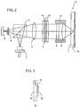
- Fig. 1 is a block diagram schematically showing the structure of an optical disc reproducing apparatus according to a first embodiment of the present invention.
- Fig. 2 is a schematic diagram showing the optical structure of an optical pickup device in Fig. 1.
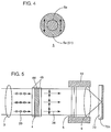
- Fig. 3 is a cross-sectional view showing the structure of a polarizing filter in Fig. 2.
- Fig. 4 is a front view of the polarizing filter shown in Fig. 3.
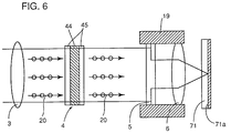
- Fig. 5 is a schematic diagram for describing operation when a digital video disc is read using the optical pickup device in Fig. 2.
- Fig. 6 is a schematic diagram for describing operation when a compact disc is read using the optical pickup device of Fig. 2.
- Fig. 7 is a graph showing the relationship between spherical aberration and numerical aperture.
- Fig. 8 is a concept diagram of an objective lens having a function of correcting aberration.
- Figs. 9A to 9G are front views showing other examples of the polarizing filter of Fig. 4.
- Figs. 10A to 10D are front views showing further examples of the polarizing filter of Fig. 4.
- Fig. 11A is a front view for describing polarizing glass
- Fig. 11B is a front view of the polarizing glass which can be used instead of the polarizing filter of Fig. 2.
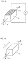
- Fig. 12 is a perspective view of a Pockels cell which can be used instead of a TN type liquid crystal in Fig. 2.
- Fig. 13 is a perspective view of a Faraday cell which can be used instead of the TN type liquid crystal in Fig. 2.
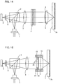
- Fig. 14 is a schematic diagram showing an optical system of an optical pickup device in an optical disc reproducing apparatus according to a second embodiment of the present invention.
- Fig. 15 is a schematic diagram showing an optical system of an optical pickup device in an optical disc reproducing apparatus according to a third embodiment of the present invention.
- Fig. 16A shows a state where a guest-host type liquid crystal in Fig. 15 is in an off state
- Fig. 16B shows a state where the guest-host type liquid crystal is in an on state.
- Fig. 17 is a schematic diagram showing an optical system of an optical pickup device in an optical disc reproducing apparatus according to a fourth embodiment of the present invention.
- Fig. 18 is a diagram showing one example of a semiconductor laser in Fig. 17.
- Fig. 19 is a diagram showing another example of the semiconductor laser in Fig. 17.
- Fig. 20 is a diagram showing still another example of the semiconductor laser in Fig. 17.
- Fig. 21 is a schematic diagram showing an optical system of an optical pickup device in an optical disc reproducing apparatus according to a fifth embodiment of the present invention.
- Fig. 22 is a schematic diagram showing an optical system of an optical pickup device in an optical disc reproducing apparatus according to a sixth embodiment of the present invention.
- Fig. 23 is a schematic diagram showing an optical system of an optical pickup device in an optical disc reproducing apparatus according to a seventh embodiment of the present invention.
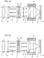
- Fig. 24 is a diagram for describing operation when a digital video disc is read using the optical pickup device of Fig. 23.
- Fig. 25 is a diagram for describing operation when a compact disc is read using the optical pickup device of Fig. 23.
- Fig. 26 is a schematic diagram showing an optical system of an optical pickup device in an optical disc reproducing apparatus according to an eighth embodiment of the present invention.
- Fig. 27 is a front view showing the structure of a TN type liquid crystal in Fig. 26.
- Fig. 28 is a cross-sectional view showing the structure of a polarizing filter in Fig. 26.
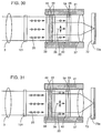
- Fig. 29 is a diagram for describing operation when an optical disc according to the SD standard is read using the optical pickup device of Fig. 26.
- Fig. 30 is a diagram for describing operation when the compact disc is read using the optical pickup device of Fig. 26.
- Fig. 31 is a diagram for describing operation when an optical disc according to the MMCD standard is read using the optical pickup device of Fig. 26.
- Fig. 32 is a schematic diagram showing an optical system of an optical pickup device in an optical disc reproducing apparatus according to a ninth embodiment of the present invention.
- Fig. 33 is a side view of the optical system of Fig. 32.
- Fig. 34 is a schematic diagram showing an optical system of an optical pickup device in an optical disc reproducing apparatus according to a tenth embodiment of the present invention.
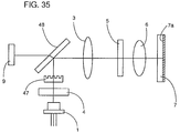
- Fig. 35 is a schematic diagram showing an optical system of an optical pickup device in an optical disc reproducing apparatus according to an eleventh embodiment of the present invention.
- Fig. 36 is a schematic diagram showing an optical system of an optical pickup device in an optical disc reproducing apparatus according to a twelfth embodiment of the present invention.
- Fig. 37 is a block diagram showing a signal processing system in an optical disc reproducing apparatus according to a thirteenth embodiment of the present invention.
- Fig. 38 is a block diagram showing the schematic structure of the optical disc reproducing apparatus according to the thirteenth embodiment of the present invention.
- Fig. 39 is a front view showing the structure of a TN type liquid crystal used in an optical pickup device in Fig. 38.
- Table 1 shows rated values and reproduction conditions of two kinds of optical discs which can be read in the optical reproducing apparatus according to the first embodiment.
- Table 1 DVD (SD) CD (Standard) Rated value Substrate thickness 0.6 mm (0.55 ⁇ 0.65 mm) 1.2 mm (1.1 ⁇ 1.3 mm) Shortest pit length 0.4 ⁇ m (0.3 ⁇ 0.5 ⁇ m) 0.83 ⁇ m (0.80 ⁇ 0.90 ⁇ m) Track pitch 0.74 ⁇ m (0.73 ⁇ 0.75 ⁇ m) 1.6 ⁇ m (1.5 ⁇ 1.7 ⁇ m) Reproduction condition Wavelength 635 nm (620 ⁇ 650 nm) Effective numerical aperture 0.60 (0.55 ⁇ 0.65) 0.35 (0.30 ⁇ 0.40)
- the optical disc reproducing apparatus can read both a digital video disc according to the SD standard of a high density and a thin substrate and a compact disc (including a CD-ROM) of a standard density and a standard substrate thickness.
- the digital video disc according to the SD standard has a substrate thickness of 0.6 (tolerance range 0.55-0.65) mm, the shortest pit length of 0.4 (tolerance range 0.3-0.5) ⁇ m, and a track pitch of 0.74 (tolerance range 0.73-0.75) ⁇ m.
- the compact disc has a substrate thickness of 1.2 (tolerance range 1.1-1.3) mm, the shortest pit length of 0.83 (tolerance range 0.80-0.90) ⁇ m, and a track pitch of 1.6 (tolerance range 1.5-1.7) ⁇ m.
- This optical disc reproducing apparatus reads both the digital video disc and the compact disc using a single laser wavelength of 635 (tolerance range 585-685, preferably 620-650) nm.
- a laser wavelength of 650 (tolerance range 600-700, preferably 635-665) nm may be used.
- an objective lens is designed to be adapted to the digital video disc.
- the numerical aperture of the objective lens is set to 0.60 (tolerance range 0.55-0.65) for the digital video disc.
- the luminous flux of a laser beam is diaphragmed in reading of the compact disc so that the effective numerical aperture of the objective lens is changed to 0.35 (tolerance range 0.30-0.40) for the compact disc.
- an optical disc reproducing apparatus 14 of the first embodiment includes an optical pickup device 15 picking up information recorded on an optical disc 13, a determining circuit 16 determining the thickness of a substrate 7 of optical disc 13, a reproduction signal processing circuit 17 processing a reproduction signal from optical pickup device 15, and a tracking control circuit 18 carrying out tracking control for an actuator (not shown) in optical pickup device 15 in response to a tracking error signal from optical pickup device 15.
- optical pickup device 15 includes a semiconductor laser 1 generating a laser beam having a wavelength of 635 (tolerance ⁇ 15) nm, a half prism 2, a collimator lens 3, a polarization plane rotating unit 4, a polarizing filter 5, an objective lens 6 focusing the laser beam to optical disc 13, a lens holder 19 holding objective lens 6 and polarizing filter 5 together, a condenser lens 8, and a photodetector 9. Therefore, the laser beam from semiconductor laser 1 is reflected by half prism 2, made parallel by collimator lens 3, and enters objective lens 6 through polarization plane rotating unit 4 and polarizing filter 5.
- Objective lens 6 together with polarizing filter 5 fixed thereto are displaced in the tracking direction by tracking control circuit 18 in Fig. 1, and in its optical axis direction (focus direction) by a focus control mechanism (not shown).
- the laser beam through objective lens 6 is converged to be directed to a recording surface 7a of optical disc 13 through substrate 7 made of polycarbonate.
- the laser beam reflected by recording surface 7a enters condenser lens 8 through substrate 7, objective lens 6, polarizing filter 5, polarization plane rotating unit 4, collimator lens 3, and half prism 2.
- the laser beam passing through condenser lens 8 is converged to be directed to photodetector 9.
- photodetector 9 In response to the directed laser beam, photodetector 9 generates a reproduction signal and a tracking error signal.
- objective lens 6 is preferably designed to make small aberration due to difference in thickness of substrate 7.
- Polarization plane rotating unit 4 includes a TN (Twisted Nematic) type liquid crystal 44, and two transparent electrode plates 45 sandwiching liquid crystal 44. Since no voltage is applied to transparent electrode plates 45 in reading of the digital video disc, polarization plane rotating unit 4 rotates the plane of polarization of the laser beam by 90°. On the other hand, since a predetermined voltage is applied to transparent electrode plates 45 in reading of the compact disc, polarization plane rotating unit 4 does not rotate the plane of polarization of the laser beam. Therefore, the entering laser beam directly passes through polarization plane rotating unit 4.
- TN Transmission Nematic
- polarizing filter 5 includes a doughnut-shaped polarizing film 51, two glass plates 52 sandwiching film 51, and a filter 53 having no polarization characteristics laminated on the surface of glass plate 52 on the side of objective lens 6.
- Polarizing film 51 shades a laser beam having the plane of polarization perpendicular to the surface of paper on which the figure is drawn (hereinafter referred to as a "paper surface"). Therefore, polarizing film 51 transmits a laser beam having the plane of polarization parallel to the paper surface with transmittance of approximately 70 to 90 %.
- filter 53 When the laser beam having the plane of polarization parallel to the paper surface is directed, if filter 53 is not provided, there could be a difference in transmittance between the central portion and the peripheral portion of polarizing filter 5. In order to avoid this, filter 53 has transmittance of approximately 70 to 90 %, and equalizes transmittance of polarizing filter 5 in the entire surface thereof when the laser beam having the plane of polarization parallel to the paper surface is directed. As far as it is transparent and superior in optical characteristics, any material can be used for glass plate 52. Polycarbonate and a resin such as PMMA, for example, may be used instead of glass. Since polarizing filter 5 is fixed to objective lens 6, the lighter polarizing filter 5 is, the more stably tracking control and focus control of objective lens 6 may be carried out.
- filter 53 is not required.
- polarization characteristics of polarizing filter 5 are shown in Fig. 4.
- a peripheral portion 5a of polarizing filter 5 transmits only a laser beam polarizing in the longitudinal direction of the figure.
- a central portion (transparent aperture) 5b of polarizing filter 5 transmits a laser beam polarizing in any direction.
- the diameter of central portion 5b of polarizing filter 5 is set to 2.3 (tolerance ⁇ 0.2) mm so that the effective numerical aperture of objective lens 6 becomes 0.35 (tolerance ⁇ 0.05).
- the diameter of central portion 5b of polarizing filter 5 may be set so that the effective numerical aperture of objective lens 6 is 0.35.
- determining circuit 16 in Fig. 1 determines the thickness of substrate 7 of optical disc 13 to be read, and applies a determination signal indicating the determined thickness to optical pickup device 15.
- optical pickup device 15 is adapted so that the laser beam is converged on recording surface 7a of optical disc 13.
- TN type liquid crystal 44 rotates the plane of polarization of the laser beam by 90° as shown in Fig. 5, so that a laser beam 20 having the plane of polarization perpendicular to the paper surface from collimator lens 3 is entirely changed into a laser beam 38 having the plane of polarization parallel to the paper surface. Since the central portion of polarizing filter 5 does not have the polarization characteristic, laser beam 38 passes through the central portion. On the other hand, although the peripheral portion of polarizing filter 5 has the polarization characteristic, the direction of polarization matches that of laser beam 21. Therefore, laser beam 38 passes through both the peripheral portion and the central portion similarly.
- the entire laser beam 38 enters objective lens 6 without being shaded by polarizing filter 5.
- the laser beam is converged on a recording surface 70a of a digital video disc 70 by objective lens 6.
- the diameter of the beam spot formed on recording surface 70a is 0.9 (tolerance ⁇ 0.1) ⁇ m.
- a predetermined voltage is applied to transparent electrode plates 45 of polarization plane rotating unit 4. Therefore, TN type liquid crystal 44 transmits laser beam 20 directly without rotating its plane of polarization, as shown in Fig. 6.
- laser beam 20 from polarization plane rotating unit 4 has the plane of polarization perpendicular to the paper surface, which is the same as that of laser beam 20 from collimator lens 3. Since the central portion of polarizing filter 5 does not have the polarization characteristic, laser beam 20 passes through the central portion. Since the peripheral portion of polarizing filter 5 has the polarization characteristics in the direction perpendicular to laser beam 20, however, laser beam 20 is shaded at the peripheral portion.
- laser beam 20 enters objective lens 6 only through the central portion of polarizing filter 5.
- This laser beam 20 is converged on a recording surface 71a of a compact disc by objective lens 6.
- the diameter of the beam spot formed on recording surface 71a is 1.5 (tolerance ⁇ 0.1) ⁇ m.
- objective lens 6 is designed to be adapted to the digital video disc according to the SD standard having a substrate 70 of 0.6 mm in thickness. Therefore, this objective lens 6 has a numerical aperture of 0.6 (tolerance ⁇ 0.05).
- spherical aberration is proportionate to the biquadratic of the numerical aperture. This is because there is a difference in optical path between a laser beam reaching recording surface 70a through the center of objective lens 6 and a laser beam reaching recording surface 70a through the outermost periphery of objective lens 6, as shown in Fig. 8. Therefore, objective lens 6 is designed so as to minimize such spherical aberration.
- the central portion of objective lens 6 is designed so as to minimize aberration in reading of an optical disc of a little more than 0.6 mm in thickness. Since aberration of the central portion of objective lens 6 in reading of an optical disc of 0.6 mm in thickness becomes a little greater in this case, it is desired that the peripheral portion of objective lens 6 is designed to reduce the aberration.
- the effective numerical aperture of objective lens 6 is 0.35 (tolerance ⁇ 0.05), since polarizing filter 5 shades the laser beam to the peripheral portion of objective lens 6 as described above. Since the laser beam does not enter the peripheral portion of objective lens 6 designed for a digital video disc, objective lens 6 can converge the laser beam on recording surface 71a of the compact disc. Therefore, in reading of the digital video disc, objective lens 6 converges the laser beam incident on its entire portion on recording surface 70a of the digital video disc. In reading of the compact disc, objective lens 6 converges only the laser beam incident on the central portion on recording surface 71a of the compact disc.
- this optical disc reproducing apparatus can read not only the digital video disc but also the compact disc.
- the optical disc reproducing apparatus includes a reflecting mirror for changing the optical path of the laser beam by 90° between collimator lens 3 and polarizing filter 5, this mirror is not shown.
- This reflecting mirror makes the optical pickup device thin by changing the optical path as described above.
- the effective numerical aperture of objective lens 6 changes according to the thickness of substrate 7 in the first embodiment, the effective numerical aperture may change according to the recording density instead of the thickness of substrate 7.
- polarization plane rotating unit 4 is positioned between collimator lens 3 and polarizing filter 5.
- polarization plane rotating unit 4 may be positioned between semiconductor laser 1 and half prism 2, or between half prism 2 and collimator lens 3.
- polarizing filter 5 has a circular transparent aperture at its central portion as shown in Fig. 4, polarizing filter 5 may have a polygonal transparent aperture such as a triangle and an octagon instead of such a circular transparent aperture as shown in Figs. 9A to 9G.
- polarizing filter 5 When polarizing filter 5 is fixed to objective lens 6 as in the above described first embodiment, the optical axis of objective lens 6 always matches the center of the transparent aperture of polarizing filter 5. Therefore, displacement of objective lens 6 in the tracking direction does not cause the luminous flux of the laser beam to change.
- polarizing filter 5 may be provided independently apart from objective lens 6. Polarizing filter 5 is not necessarily fixed to objective lens 6. In this case, objective lens 6 is desirably fixed to the optical axis of the laser beam. If satisfactory reproduction cannot be carried out, the transparent aperture may be extended in the movement direction of objective lens 6. Since objective lens 6 and polarizing filter 5 are displaced in the tracking direction by tracking control circuit 18, the transparent aperture may be longer from side to side as shown in Figs. 10A to 10D, for example.
- the shorter side is 2.3 mm, and the longer side is 2.5 to 3.3 mm. Further, the transparent aperture may be in asymmetry. Since a CD player carrying out reproduction using the transparent aperture reproduces information from inward to outward of a disc, the transparent aperture is elongated in the outward tracking direction of the disc.
- a hologram element having the polarization characteristics or polarizing glass shown in Figs. 11A and 11B may be used instead of polarizing filter 5.
- an optical thin film having the polarization characteristics may be formed on the surface of an optical component such as a reflecting mirror positioned between polarization plane rotating unit 4 and objective lens 6.
- Polarizing glass is manufactured by orienting silver compounds in glass in a predetermined direction and reducing the surface to deposit silver as shown in Fig. 11A.
- the reduced silver film has the polarization characteristic.
- peripheral portion 5a of the polarizing glass has the polarization characteristic, while central portion 5b does not have the polarization characteristic.
- the laser beam having the plane of polarization the same as the polarization characteristics of peripheral portion 5a can pass through peripheral portion 5a by 100 %. Therefore, it is not necessary to provide filter 53 for decreasing transmittance at the central portion as shown in Fig. 3. Even if the luminous flux of the laser beam is diaphragmed, a sufficient quantity of light can be obtained. It is desirable to use silver as a material for providing the polarizing glass with the polarization characteristic. However, any other metal material may be used as far as it provides the polarization characteristic.
- TN type liquid crystal 44 is used for electrically rotating the plane of polarization.
- STN (Super Twisted Nematic) type liquid crystal or a ferroelectric liquid crystal may be used instead.
- the ferroelectric liquid crystal rotates the plane of polarization of the laser beam by 45° in response to application of a positive voltage in a short time, and maintains such a state.
- the ferroelectric liquid crystal rotates the plane of polarization of the laser beam by 45° in the direction opposite to that in application of the positive voltage, and maintains such a state. Therefore, by applying the positive voltage in reading of the digital video disc and the negative voltage in reading of the compact disc, for example, the ferroelectric liquid crystal can rotate the plane of polarization of the laser beam by 90°. Using such a ferroelectric liquid crystal shortens a voltage application time for rotating the plane of polarization, resulting in reduction of power consumption.
- a Pockels cell 56 shown in Fig. 12 may be used instead of TN type liquid crystal 44.
- Pockels cell 56 changes laser beam 20 having the plane of polarization in the longitudinal direction on the figure into laser beam 38 having the plane of polarization in the transverse direction upon application of a predetermined voltage. Since the angle of rotation of the plane of polarization can be changed by adjusting the voltage to be applied, the angle of rotation of the plane of polarization can be adjusted so that an optimal reproduction characteristics can be obtained.
- a Faraday cell 23 magnetically rotating the plane of polarization shown in Fig. 13 may be used instead of TN type liquid crystal 44.
- Faraday cell 23 rotates the plane of polarization of the laser beam by 90° in response to application of a magnetic field H. Since the direction of passage of the laser beam matches the direction of application of magnetic field H, a coil is wound around a tube holding Faraday cell 23, for example. Therefore, assembly and structure of Faraday cell 23 can be simplified.
- half prism 2 is used.
- a polarizing beam splitter may be used instead of half prism 2, and a quarter-wave plate may be inserted between polarizing filter 5 and objective lens 6. According to such a structure, the use efficiency of the laser beam is improved.
- the laser beam of 635 nm in wavelength is used.
- a laser beam of 650 (tolerance ⁇ 15) nm in wavelength may be used.
- the spot diameter of the laser beam increases by approximately 0.1 ⁇ m, satisfactory reproduction can be carried out. If the tolerance of wavelength 635 nm is ⁇ 50 nm, or if the tolerance of wavelength 650 nm is ⁇ 50 nm, satisfactorily reproduction can be carried out.
- objective lens 6 has a numerical aperture of 0.6 so as to be adapted to the digital video disc according to the SD standard. However, if objective lens 6 has a numerical aperture of 0.52 so as to be adapted to the substrate of 1.2 mm in thickness, both the compact disc and the digital video disc according to the MMCD standard can be read. According to the MMCD standard, an optical disc has a substrate of 1.2 (tolerance ⁇ 0.05) mm in thickness and a high recording density. In this case, the compact disc can be read even if the effective numerical aperture of objective lens 6 is not 0.35. However, if the effective numerical aperture of objective lens 6 is 0.35, coma generated by the tilt or warp of the substrate is decreased, allowing more favorable reproduction.
- polarizing film 51 transmitting only the laser beam having the plane of polarization parallel to the paper surface is used.
- a polarizing film transmitting only the laser beam having the plane of polarization perpendicular to the paper surface may be used instead.
- polarizing filter 5 in Fig. 2 is laminated on the surface of objective lens 6, whereby polarizing filter 5 is fixed to objective lens 6.
- the second embodiment is made more compact than the first embodiment.
- An optical thin film having the polarization characteristics may be formed on the surface of objective lens 6 instead of polarizing filter 5.
- the optical disc reproducing apparatus includes a liquid crystal shutter 24 instead of polarization plane rotating unit 4 and polarizing filter 5 in Fig. 2.
- Liquid crystal shutter 24 includes a doughnut-shaped guest-host type liquid crystal 25 and transparent electrode plates 26 sandwiching liquid crystal 25. Liquid crystal shutter 24 is fixed to objective lens 6 by a lens holder 19.
- liquid crystal shutter 24 transmits the laser beam as it is.
- liquid crystal shutter 24 transmits only the laser beam through the central portion.
- Liquid crystal shutter 24 shades the laser beam at the peripheral portion by scattering.
- Liquid crystal shutter 24 transmits the entire laser beam in reading of the digital video disc, and transmits only the central portion of the laser beam in reading of the compact disc. Therefore, the third embodiment does not require polarizing filter 5 shown in Fig. 2.
- the optical disc reproducing apparatus includes a semiconductor laser 27 which can selectively generate two laser beams different in the plane of polarization.
- the optical disc reproducing apparatus according to this embodiment does not include polarization plane rotating unit 4 in Fig. 2, unlike the optical disc reproducing apparatus of the first embodiment.
- This optical disc reproducing apparatus can also read both the digital video disc according to the SD standard and the compact disc.
- a laser beam having the plane of polarization perpendicular to the paper surface is emitted from semiconductor laser 27 to enter polarizing filter 5 through half prism 2 and collimator lens 3.
- Polarizing filter 5 transmits the entire laser beam without shading. Therefore, objective lens 6 converges the laser beam on a recording surface of the digital video disc.
- a laser beam having the plane of polarization parallel to the paper surface is emitted from semiconductor laser 27 to enter polarizing filter 5 through half prism 2 and collimator lens 3.
- Polarizing filter 5 shades the peripheral portion of the incident laser beam and transmits only the central portion of the laser beam. Therefore, objective lens 6 converges the laser beam on a recording surface of the compact disc.
- Such semiconductor laser 27 as described above which can selectively generate two laser beams having the planes of polarization orthogonal to each other may be used instead of polarization plane rotating unit 4 of the first embodiment. Several examples of such semiconductor laser 27 will be described hereinafter.
- semiconductor laser 27 includes a laser element 28 generating a laser beam polarizing in the longitudinal direction on the figure, another laser element 29 generating a laser beam polarizing in the transverse direction on the figure, and a sub-mount 30 to which both laser elements 28 and 29 are mounted together.
- the laser beams are emitted rightward in Fig. 18. However, these laser beams are actually emitted toward this side of the paper surface. This is also true in Figs. 19 and 20.
- semiconductor laser 27 shown in Fig. 18 laser elements 28 and 29 are activated alternately.
- laser elements 31 and 32 having the planes of polarization orthogonal to each other may be formed on a semiconductor substrate 33 integrally.
- Rotating driver 34 includes, for example, a sub-mount (not shown) holding semiconductor laser 27 and a servo motor (not shown) rotating the sub-mount by 90°.
- the optical disc reproducing apparatus includes two semiconductor lasers 11 and 12 instead of semiconductor laser 1 in Fig. 2, a polarizing beam splitter 21 focusing laser beams from semiconductor lasers 11 and 12 to half prism 2, two photodetectors 91 and 92 instead of photodetector 9 in Fig. 2, two condenser lenses 81 and 82 instead of condenser lens 8 in Fig. 2, and a polarizing beam splitter 22 focusing the laser beam from half prism 2 to condenser lenses 81 and 82.
- This optical disc reproducing apparatus does not include polarization plane rotating unit 4 in Fig. 2.
- Semiconductor laser 11 generates a laser beam having the plane of polarization parallel to the paper surface.
- the generated laser beam reaches recording surface 7a of the optical disc through polarizing beam splitter 21.
- Light reflected from the recording surface of the optical disc reaches photodetector 91 through polarizing beam splitter 22.
- semiconductor laser 12 generates a laser beam having the plane of polarization perpendicular to the paper surface.
- the generated laser beam reaches recording surface 7a of the optical disc after reflection from polarizing beam splitter 21.
- the light reflected from recording surface 7a of the optical disc reaches photodetector 92 after reflection from polarizing beam splitter 22. Since such two semiconductor lasers 11 and 12 are activated alternately, the optical disc reproducing apparatus according to the fifth embodiment can also read both the digital video disc and the compact disc.
- the optical disc reproducing apparatus includes a half-wave plate 35 and a slide driver 36 instead of polarization plane rotating unit 4, unlike the optical disc reproducing apparatus according to the first embodiment.
- Slide driver 36 inserts half-wave plate 35 in the optical path of the laser beam in reading of the digital video disc, and removes half-wave plate 35 from the optical path in reading of the compact disc. Therefore, when half-wave plate 35 is not inserted in the optical path, the plane of polarization of the laser beam is not rotated. However, when half-wave plate 35 is inserted in the optical path, the plane of polarization of the laser beam is rotated by half-wave plate 35 by 90°.
- Slide driver 36 includes, for example, a circular plate (not shown) holding half-wave plate 35 and a servo motor (not shown) rotating the circular plate. As described above, half-wave plate 35 may be inserted/removed mechanically.
- the optical disc reproducing apparatus includes, unlike that of the first embodiment, an objective lens 37 designed to be adapted to a substrate of 0.8 mm in thickness, and a spherical aberration correcting plate 10 of an aspherical shape inserted between collimator lens 3 and polarization plane rotating unit 4.
- This optical disc reproducing apparatus can reproduce information recorded on the digital video disc according to the SD standard, the compact disc, and the digital video disc according to the MMCD standard.
- Spherical aberration correcting plate 10 corrects spherical aberration of objective lens 37 according to the type of optical disc to be read.
- Spherical aberration correcting plate 10 is formed of a hologram element, a diffraction grating and the like, for example.
- a spherical aberration correcting plate 100 for a thin substrate is inserted, and no voltage is applied to transparent electrode plates 45 of polarization plane rotating unit 4, as shown in Fig. 24. Since polarization plane rotating unit 4 rotates the plane of polarization of laser beam 20 by 90° similarly in the first embodiment, the entire laser beam 38 passing through polarization plane rotating unit 4 is transmitted through polarizing filter 5.
- objective lens 37 in the seventh embodiment is designed to be adapted to a substrate of 0.8 mm in thickness as described above, spherical aberration would be produced without spherical aberration correcting plate 100. However, since spherical aberration correcting plate 100 is inserted in the seventh embodiment, objective lens 37 converges laser beam 38 on recording surface 70a of the digital video disc according to the SD standard without spherical aberration being produced.
- a spherical aberration correcting plate 101 for a substrate of a standard thickness is inserted, and a predetermined voltage is applied to transparent electrode plates 45 of polarization plane rotating unit 4, as shown in Fig. 25. Therefore, similar to the case of the first embodiment, polarization plane rotating unit 4 transmits laser beam 20 without rotating the plane of polarization.
- Polarizing filter 5 shades the peripheral portion of laser beam 20, and transmits only the central portion of laser beam 20.
- objective lens 37 converges laser beam 20 on recording surface 71a of the compact disc or the digital video disc according to the MMCD standard without spherical aberration being produced.
- polarization plane rotating unit 4 is provided between spherical aberration correcting plate 10 and polarizing filter 5, and spherical aberration correcting plate 10 is provided between collimator lens 3 and polarization plane rotating unit 4.
- polarization plane rotating unit 4 and spherical aberration correcting plate 10 may be provided between semiconductor laser 1 and half prism 2 or between collimator lens 3 and polarizing filter 5.
- Spherical aberration correcting plate 10 may be provided between half prism 2 and collimator lens 3 or between collimator lens 3 and polarizing filter 5. More specifically, polarization plane rotating unit 4 and spherical aberration correcting plate 10 may be positioned anywhere as far as they are closer to semiconductor laser 1 than polarizing filter 5.
- Polarization plane rotating unit 4 and spherical aberration correcting plate 10 may be positioned oppositely to the case of Fig. 23.
- objective lens 37 is designed to be adapted to substrate 7 of 0.8 mm in thickness in the seventh embodiment
- objective lens 37 may be designed to be adapted to a substrate of other than 0.8 mm in thickness, for example, 0.6 to 1.2 mm in thickness.
- the objective lens is designed to be approximately adapted to a substrate of 0.6 mm in thickness
- the digital video disc according to the SD standard having substrate 70 of 0.6 mm in thickness can be read stably.
- the objective lens is designed to be approximately adapted to a substrate of 1.2 mm in thickness
- the compact disc or the digital video disc according to the MMCD standard having substrate 71 of 1.2 mm in thickness can be read stably.
- spherical aberration correcting plate 100 for a thin substrate in Fig. 24 does not have to be inserted.
- spherical aberration correcting plate 101 for a substrate of a standard thickness in Fig. 25 does not have to be inserted.
- Objective lens 37 is designed to be adapted to a substrate of 0.8 mm in thickness as in the seventh embodiment. Further, spherical aberration correcting plate 10 is inserted between collimator lens 3 and polarization plane rotating unit 39 as in the seventh embodiment.
- the optical disc reproducing apparatus can read the digital video disc according to the SD standard, the compact disc, and the digital video disc according to the MMCD standard.
- polarization plane rotating unit 39 is divided into three areas 41 to 43 as shown in Fig. 27. More specifically, divided transparent conductive films are formed on glass substrates of transparent electrode plates 46 corresponding to these three areas 41 to 43. Therefore, the laser beam passes through the area to which a voltage is applied without its plane of polarization being rotated, and the laser beam passes through the area to which no voltage is applied with its plane of polarization being rotated by 90°.
- the diameter of middle area 42 is set in proportion to the effective luminous flux diameter so that the effective numerical aperture is 0.52, and the diameter of innermost area 43 is set in proportion to the effective luminous flux diameter so that the effective numerical aperture is 0.35.
- polarizing filter 40 includes a polarizing film 54 transmitting only the laser beam having the plane of polarization parallel to the paper surface, and two glass plates 55 sandwiching polarizing film 54. Unlike patterned polarizing film 51 in Fig. 3, polarizing film 54 is sandwiched between the entire surfaces of two glass plates 55.
- spherical aberration correcting plate 100 for a thin substrate is inserted, and no voltage is applied to any of areas 41 to 43 of polarization plane rotating unit 39, as shown in Fig. 29. Therefore, the entire laser beam 20 incident on polarization plane rotating unit 39 is transmitted, and its plane of polarization is rotated by 90°. The entire laser beam 38 having the plane of polarization parallel to the paper surface is transmitted through polarizing filter 40. As a result, objective lens 37 converges the entire laser beam 38 on recording surface 70a of the digital video disc according to the SD standard.
- spherical aberration correcting plate 101 for a substrate of a standard thickness is inserted, and a predetermined voltage is applied to areas 41 and 42 of polarization plane rotating unit 39, as shown in Fig. 30. Therefore, the laser beam passes through areas 41 and 42 without its plane of polarization rotated. Although laser beam 20 passes through innermost area 43, its plane of polarization is rotated by 90°.
- Polarizing filter 40 shades laser beam 20 passing through areas 41 and 42 and having the plane of polarization perpendicular to the paper surface, and transmits laser beam 38 passing through innermost area 43 and having the plane of polarization parallel to the paper surface.
- objective lens 37 converges only the central portion of the laser beam on a recording surface 72a of the compact disc.
- spherical aberration correcting plate 101 for a substrate of a standard thickness is inserted, and a predetermined voltage is applied only to outermost area 41 of polarization plane rotating unit 39, as shown in Fig. 31. Therefore, laser beam 20 passes through outermost area 41 without its plane of polarization rotated. Although laser beam 20 passes through middle and innermost areas 42 and 43, the plane of polarization is rotated by 90°.
- Polarizing filter 40 shades laser beam 20 passing through outermost area 41 and having the plane of polarization perpendicular to the paper surface, and transmits laser beam 38 passing through middle and innermost areas 42 and 43 and having the plane of polarization parallel to the paper surface.
- objective lens 37 converges only the central portion (wider than that of Fig. 30) of the laser beam on a recording surface 73a of the digital video disc according to the MMCD standard.
- patterned polarization plane rotating unit 39 and non-patterned polarizing filter 40 change the effective numerical aperture of objective lens 37 according to the thickness of substrate 7 of the optical disc to be read. Therefore, the optical disc reproducing apparatus of this embodiment can read the digital video disc according to the SD standard, the compact disc, and the digital video disc according to the MMCD standard.
- the polarization plane rotating unit may be patterned instead of the polarizing filter. In this case, polarizing filter 40 does not have to be patterned.
- the optical disc reproducing apparatus includes a half mirror plate 48 instead of half prism 2, as shown in Fig. 32.
- Patterned polarization plane rotating unit 39 is inserted between half mirror plate 48 and a diffraction grating 47.
- diffraction grating 47 and a reflecting mirror 49 are shown, which are not shown in the above embodiments.
- Diffraction grating 47 forms two beam spots for tracking control in addition to a beam spot for reproduction.
- polarizing filter 40 shown in Fig. 33 does not have to be patterned.
- polarization plane rotating unit 39 may be provided not just in front of polarizing filter 40 but between half mirror plate 48 and diffraction grating 47.
- the optical disc reproducing apparatus includes half mirror plate 48 instead of half prism 2, as shown in Fig. 34.
- Non-patterned polarization plane rotating unit 4 is inserted between half mirror plate 48 and diffraction grating 47. Since polarization plane rotating unit 4 is not patterned unlike in the ninth embodiment, polarizing filter 5 is patterned. In Fig. 34, the reflecting mirror is not shown.
- polarization plane rotating unit 4 and diffraction grating 47 are positioned oppositely to those of Fig. 34, as shown in Fig. 35.
- polarization plane rotating unit 4 may be inserted between diffraction grating 47 and semiconductor laser 1.
- non-patterned polarizing filter 40 is laminated not just in front of objective lens 6 but on the rear surface of patterned polarization plane rotating unit 39, unlike in Fig. 32.
- Such integration of polarization plane rotating unit 39 and polarizing filter 40 simplifies structure and assembly required for changing the effective numerical aperture of objective lens 6.
- polarization plane rotating unit 39 is patterned, and polarizing filter 40 is not patterned.
- the polarizing filter may be patterned, and the polarization plane rotating unit may not be patterned.
- reproduction signal processing circuit 17 of Fig. 1 preferably includes an amplifier 90a for MMCD and an amplifier 90b for SD or CD.
- tracking control circuit 18 in Fig. 1 preferably includes an amplifier 91a for MMCD and an amplifier 91b for SD or CD.
- the reproduction signal generated by the photodetector is amplified by amplifier 90a or 90b, and the amplified reproduction signal is applied to a reproduction signal processing portion 90c.
- the tracking error signal simultaneously generated by the photodetector is amplified by amplifier 91a or 91b, and the amplified tracking error signal is applied to a tracking control portion 91c.
- Amplifier 90a for MMCD has a larger gain than amplifier 90b for SD or CD. Amplifier 90a has a large gain particularly in a high frequency component of the reproduction signal. Amplifier 90a for MMCD is activated in reading of the digital video disc according to the MMCD standard, and amplifier 90b for SD or CD is activated in reading of the digital video disc according to the SD standard or the compact disc.
- Amplifier 91a for MMCD has a larger gain than amplifier 91b for SD or CD.
- Amplifier 91a for MMCD is activated in reading of the digital video disc according to the MMCD standard, and amplifier 91b for SD or CD is activated in reading of the digital video disc according to the SD standard or the compact disc.
- the reproduction signal is amplified by amplifier 90a for MMCD more significantly than in reading of the digital video disc according to the SD standard or the compact disc, to be applied to reproduction signal processing portion 90c.
- the tracking error signal is amplified by amplifier 91a for MMCD more significantly in reading of the digital video disc according to the MMCD standard than in reading of the digital video disc according to the SD standard or the compact disc, to be applied to tracking control portion 91c.
- a focus error signal is also preferably amplified more significantly in reading of the digital video disc according to the MMCD standard than in reading of the digital video disc according to the SD standard or the compact disc.
- a laser beam having a wavelength of 585 to 685 nm or 600 to 700 nm is used.
- a laser beam having a short wavelength may be used.
- a laser beam having a wavelength in the range of 350 to 700 nm can be used.
- the effective numerical aperture of the objective lens is not limited to ones shown in the above embodiments.
- the effective numerical aperture can be set in the range of 0.20 to 0.65.
- the thickness of the substrate of the optical disc to be read is 1.2 mm and 0.6 mm in the above embodiments, the thickness is not limited thereto.
- the following table 2 shows rated values and reproduction conditions of each of optical discs when the digital video disc according to the SD standard, the compact disc, and a high density digital video disc are read using a blue laser (wavelength: 350-450 nm, typical wavelength: 415-445 nm).
- the thickness of the substrate is 0.6 (tolerance ⁇ 0.05) mm
- the pit length is 0.25 (tolerance ⁇ 0.05) ⁇ m
- the pit depth is 72 (tolerance ⁇ 10) nm
- the track pitch is 0.50 (tolerance ⁇ 0.08) ⁇ m. Therefore, the high density digital video disc has a recording density higher than the digital video disc according to the SD standard.
- the effective numerical aperture of the objective lens is set to 0.20-0.30 in reading of the compact disc, 0.36-0.46 in reading of the digital video disc according to the SD standard, and 0.55-0.65 in reading of the high density digital video disc.
- the objective lens is preferably designed to be adapted to the high density digital video disc, with the numerical aperture of 0.55-0.65.
- the effective numerical aperture of the objective lens can be changed to 0.36-0.46 or 0.20-0.30.
- the objective lens is preferably designed to be adapted to the digital video disc according to the SD standard, having the numerical aperture of 0.36-0.60.
- the effective numerical aperture of the objective lens can be changed to 0.20-030.
- the effective numerical aperture of the objective lens can be changed with the method indicated in the above embodiments. Therefore, although the digital video disc according to the SD standard, the compact disc, and the high density digital video disc can be read with the blue laser, the blue laser is suitable for reading of the digital video disc according to the SD standard and the high density digital video disc.
- the following table 3 shows rated values and reproduction conditions of respective optical discs when the above described three kinds of optical discs are read with a green laser (wavelength: 450-550 nm, typical wavelength: 517-547 nm).
- Table 3 DVD (SD) CD (Standard) High density DVD Rated value
- the effective numerical aperture of the objective lens is set to 0.25-0.35 in reading of the compact disc, 0.45-0.55 in reading of the digital video disc according to the SD standard, and 0.55-0.65 in reading of the high density digital video disc.
- the objective lens is preferably designed to be adapted to the high density digital video disc, having the numerical aperture of 0.55-0.65.
- the effective numerical aperture of the objective lens can be changed to 0.45-055 or 0.25-0.35.
- the objective lens is preferably designed to be adapted to the digital video disc according to the SD standard, having the numerical aperture of 0.45-0.60.
- the effective numerical aperture of the objective lens can be changed to 0.25-035.
- the effective numerical aperture of the objective lens can also be changed with the method indicated in the above embodiments.
- the green laser is suitable for reading of the digital video disc according to the SD standard and the compact disc, the green laser can also read the high density digital video disc.
- the digital video disc according to the SD standard and the compact disc may be read with the blue laser.
- the numerical aperture of the objective lens may be set to 0.36-060, and the effective numerical aperture of the transparent aperture may be switched selectively in the range of 0.25-0.35.
- the numerical aperture of the objective lens may be set to 0.45-060, and the effective numerical aperture of the transparent aperture may be switched selectively in the range of 0.20-030.
- the present invention can be applied to recording of information on the optical disc.
- a semiconductor laser having a wavelength of 680 (tolerance ⁇ 15) nm, 650 (tolerance ⁇ 50) nm, 635 (tolerance ⁇ 50) nm, 500 (tolerance ⁇ 50) nm, or 400 (tolerance ⁇ 50) nm and a power of 30 mW, for example, information can be recorded on the digital video disc according to the SD standard, the compact disc, and the high density digital video disc.
- the effective numerical aperture of the objective lens is set so as to be adapted to the respective optical discs and the respective wavelengths.
- an optical disc reproducing apparatus 56 includes an optical pickup device 201, an amplifier 207 amplifying the reproduction signal from optical pickup device 201, a signal processing circuit 202 processing the amplified reproduction signal, an error rate calculating circuit 204 calculating an error rate produced in a predetermined period based on the output of an error detecting circuit 203 in signal processing circuit 202, a liquid crystal drive circuit 206 driving such a polarization plane rotating unit 57 as shown in Fig.
- Polarization plane rotating unit 57 has a plurality of transparent apertures 58 different in diameter as shown in Fig. 39. One of the plurality of transparent apertures 58 is selected. The plane of polarization of the laser beam passing through the selected transparent aperture is rotated. However, the plane of polarization of the laser beam passing through polarization plane rotating unit 57 excluding the selected transparent aperture 58 is not rotated.
- the diameter of transparent aperture 58 is changed according to the error rate. Therefore, the diameter of transparent aperture 58 can easily be set so that the error rate correlating with the amount of jitter is minimized.
Applications Claiming Priority (9)
| Application Number | Priority Date | Filing Date | Title |
|---|---|---|---|
| JP224395/95 | 1995-08-31 | ||
| JP22439595 | 1995-08-31 | ||
| JP22439595 | 1995-08-31 | ||
| JP25889495 | 1995-10-05 | ||
| JP25889495 | 1995-10-05 | ||
| JP258894/95 | 1995-10-05 | ||
| JP330576/95 | 1995-12-19 | ||
| JP33057695 | 1995-12-19 | ||
| JP33057695 | 1995-12-19 |
Publications (2)
| Publication Number | Publication Date |
|---|---|
| EP0762398A1 true EP0762398A1 (fr) | 1997-03-12 |
| EP0762398B1 EP0762398B1 (fr) | 2003-05-07 |
Family
ID=27330897
Family Applications (1)
| Application Number | Title | Priority Date | Filing Date |
|---|---|---|---|
| EP96103095A Expired - Lifetime EP0762398B1 (fr) | 1995-08-31 | 1996-02-29 | Appareil d'enregistrement/de reproduction pour disque optique pour l'enregistrement/la reproduction d'information sur disques optiques de types différents |
Country Status (6)
| Country | Link |
|---|---|
| US (1) | US5787061A (fr) |
| EP (1) | EP0762398B1 (fr) |
| KR (1) | KR970012343A (fr) |
| CN (1) | CN1113336C (fr) |
| DE (1) | DE69627944T2 (fr) |
| TW (1) | TW307001B (fr) |
Cited By (12)
| Publication number | Priority date | Publication date | Assignee | Title |
|---|---|---|---|---|
| EP0742554A2 (fr) * | 1995-05-08 | 1996-11-13 | Sanyo Electric Co. Ltd | Appareil de lecture d'un disque optique |
| EP0790604A3 (fr) * | 1996-02-13 | 1998-02-04 | Kabushiki Kaisha Toshiba | Dispositif de lecture pour disques optiques |
| EP0823705A1 (fr) * | 1996-02-23 | 1998-02-11 | Toyo Communication Equipment Co. Ltd. | Excitation optique et element optique correspondant |
| EP0847048A1 (fr) * | 1996-12-06 | 1998-06-10 | Nec Corporation | Elément à limitation d'ouverture et tête optique pourvue d'un tel élément |
| EP0851415A1 (fr) * | 1996-12-26 | 1998-07-01 | Nec Corporation | Tête optique pour un appareil d'entraínement de disque optique |
| WO1998047135A2 (fr) * | 1997-04-16 | 1998-10-22 | Matsushita Electric Industrial Co., Ltd. | Disque et dispositif pour faire un enregistrement sur un disque |
| EP0880131A2 (fr) * | 1997-05-19 | 1998-11-25 | Sony Corporation | Appareil et méthodes pour l'enregistrement et/ou la reproduction de données sur disques optiques, et cassette à disque pour tels disques |
| EP0915460A1 (fr) * | 1997-04-24 | 1999-05-12 | SANYO ELECTRIC Co., Ltd. | Dispositif de reproduction optique |
| FR2772506A1 (fr) * | 1997-12-16 | 1999-06-18 | Daewoo Electronics Co Ltd | Systeme de lecture optique compact pour une utilisation avec des disques optiques d'epaisseurs differentes |
| EP0994470A2 (fr) * | 1998-10-14 | 2000-04-19 | Sony Corporation | Support d'enregistrement optique, et appareil d'enregistrement / de reproduction optique |
| EP1028419A1 (fr) * | 1997-09-10 | 2000-08-16 | Citizen Watch Co., Ltd. | Dispositif optique |
| US6278560B1 (en) | 1998-12-21 | 2001-08-21 | U.S. Philips Corporation | Optical scanning device |
Families Citing this family (22)
| Publication number | Priority date | Publication date | Assignee | Title |
|---|---|---|---|---|
| DE19544966A1 (de) * | 1995-12-04 | 1997-06-05 | Thomson Brandt Gmbh | Gerät zum Beschreiben und/oder Lesen optischer Aufzeichnungsträger unterschiedlichen Aufbaus |
| US6821707B2 (en) | 1996-03-11 | 2004-11-23 | Matsushita Electric Industrial Co., Ltd. | Optical information recording medium, producing method thereof and method of recording/erasing/reproducing information |
| JP3795998B2 (ja) * | 1996-04-30 | 2006-07-12 | パイオニア株式会社 | 波面収差補正ユニット、波面収差補正装置及び光ピックアップ |
| US6503690B1 (en) * | 1997-08-12 | 2003-01-07 | Matsushita Electric Industrial Co., Ltd. | Optical information recording medium, method for producing the same, and method for recording and reproducing optical information |
| JPH11134720A (ja) | 1997-08-28 | 1999-05-21 | Matsushita Electric Ind Co Ltd | 光学的情報記録媒体及びその記録再生方法 |
| US6343062B1 (en) | 1997-09-26 | 2002-01-29 | Matsushita Electric Industrial Co., Ltd | Optical disk device and optical disk for recording and reproducing high-density signals |
| US6463539B1 (en) * | 1997-09-30 | 2002-10-08 | Victor Company Of Japan, Ltd. | Managing system for reproducing information composed of information recording medium, managing medium, and reproduction method and apparatus method therefor |
| KR100278786B1 (ko) * | 1998-06-18 | 2001-01-15 | 구자홍 | 광기록매체와 광 기록/재생 방법 및 장치 |
| TW448443B (en) | 1998-08-05 | 2001-08-01 | Matsushita Electric Ind Co Ltd | Optical information storage media and production method as well as the storage reproducing method and device |
| CN1311449C (zh) * | 1998-11-09 | 2007-04-18 | 松下电器产业株式会社 | 光信息处理装置和光学元件 |
| US6714351B2 (en) | 1999-12-29 | 2004-03-30 | Metrologic Instruments, Inc. | Illumination apparatus with polarizing elements for beam shaping |
| TW464769B (en) * | 2000-05-10 | 2001-11-21 | Ind Tech Res Inst | Optical device to vary the numerical aperture |
| JP4136273B2 (ja) * | 2000-05-24 | 2008-08-20 | パイオニア株式会社 | 収差補正ユニット、光ピックアップ装置及び記録再生装置 |
| US7012875B2 (en) * | 2000-09-06 | 2006-03-14 | Hitachi, Ltd. | Optical disk apparatus using focal shift signals to control spherical aberration |
| JP2004516594A (ja) * | 2000-12-11 | 2004-06-03 | コーニンクレッカ フィリップス エレクトロニクス エヌ ヴィ | 記録担体を読み取る及び/又は該記録担体に書き込むデバイス |
| US6940798B2 (en) * | 2000-12-12 | 2005-09-06 | Sony Corporation | Optical-disk reproducing apparatus, optical pickup apparatus and optical-disk recording and reproducing apparatus |
| JP2003317237A (ja) * | 2002-04-19 | 2003-11-07 | Tdk Corp | 光記録媒体判別装置及び光記録媒体判別方法 |
| JP4047074B2 (ja) * | 2002-06-03 | 2008-02-13 | Tdk株式会社 | 光記録再生方法及び光記録媒体 |
| US7911926B2 (en) * | 2005-10-18 | 2011-03-22 | Panasonic Corporation | Optical disc drive |
| CN101874270B (zh) * | 2007-11-27 | 2012-02-01 | 三菱电机株式会社 | 光学头装置以及光盘再现系统 |
| US9323807B2 (en) * | 2010-11-03 | 2016-04-26 | Sap Se | Graphical manipulation of data objects |
| US9606069B2 (en) * | 2014-06-25 | 2017-03-28 | Kla-Tencor Corporation | Method, apparatus and system for generating multiple spatially separated inspection regions on a substrate |
Citations (6)
| Publication number | Priority date | Publication date | Assignee | Title |
|---|---|---|---|---|
| US5150234A (en) * | 1988-08-08 | 1992-09-22 | Olympus Optical Co., Ltd. | Imaging apparatus having electrooptic devices comprising a variable focal length lens |
| EP0537904A2 (fr) * | 1991-10-16 | 1993-04-21 | International Business Machines Corporation | Appareil pour l'entraînement des disques optiques |
| EP0553541A1 (fr) * | 1992-01-20 | 1993-08-04 | Pioneer Electronic Corporation | Disque optique, et appareil de reproduction de disque optique |
| US5281797A (en) * | 1991-12-26 | 1994-01-25 | Hitachi, Ltd. | Short wavelength optical disk head having a changeable aperture |
| US5477527A (en) * | 1994-02-02 | 1995-12-19 | Sanyo Electric Co., Ltd. | High density optical disc and optical disc player |
| EP0731457A2 (fr) * | 1995-03-04 | 1996-09-11 | Lg Electronics Inc. | Appareil de lecture optique apte à lire des données sur n'importe quelle genre de disque |
Family Cites Families (11)
| Publication number | Priority date | Publication date | Assignee | Title |
|---|---|---|---|---|
| JPH0785311B2 (ja) * | 1984-05-15 | 1995-09-13 | セイコーエプソン株式会社 | マルチ光学ヘッド |
| JPH0354740A (ja) * | 1989-07-24 | 1991-03-08 | Matsushita Electric Ind Co Ltd | 光学情報記録部材および光学情報記録再生装置 |
| KR930010473B1 (ko) * | 1989-09-22 | 1993-10-25 | 마쯔시다덴기산교 가부시기가이샤 | 편광소자 및 그것을 사용한 광학헤드장치 |
| US5235581A (en) * | 1990-08-09 | 1993-08-10 | Matsushita Electric Industrial Co., Ltd. | Optical recording/reproducing apparatus for optical disks with various disk substrate thicknesses |
| JPH04195937A (ja) * | 1990-11-28 | 1992-07-15 | Sanyo Electric Co Ltd | 光学式記録装置 |
| TW218427B (fr) * | 1991-06-04 | 1994-01-01 | Ibm | |
| JPH05303766A (ja) * | 1992-04-27 | 1993-11-16 | Matsushita Electric Ind Co Ltd | 光ディスク用光学素子とそれを用いた光ヘッド |
| JP3048768B2 (ja) * | 1992-10-08 | 2000-06-05 | 三洋電機株式会社 | 光学ヘッド |
| JP3268858B2 (ja) * | 1992-11-30 | 2002-03-25 | 三洋電機株式会社 | 液晶表示装置 |
| JP2995003B2 (ja) * | 1995-05-08 | 1999-12-27 | 三洋電機株式会社 | 光学式再生装置 |
| DE69627752T2 (de) * | 1995-06-05 | 2003-10-16 | Nec Corp | Optische Wiedergabekopfvorrichtung für verschiedene Plattentypen |
-
1996
- 1996-02-29 US US08/608,848 patent/US5787061A/en not_active Expired - Lifetime
- 1996-02-29 EP EP96103095A patent/EP0762398B1/fr not_active Expired - Lifetime
- 1996-02-29 DE DE69627944T patent/DE69627944T2/de not_active Expired - Fee Related
- 1996-03-15 CN CN96107316A patent/CN1113336C/zh not_active Expired - Fee Related
- 1996-03-15 TW TW085103096A patent/TW307001B/zh active
- 1996-03-27 KR KR1019960008561A patent/KR970012343A/ko not_active Application Discontinuation
Patent Citations (6)
| Publication number | Priority date | Publication date | Assignee | Title |
|---|---|---|---|---|
| US5150234A (en) * | 1988-08-08 | 1992-09-22 | Olympus Optical Co., Ltd. | Imaging apparatus having electrooptic devices comprising a variable focal length lens |
| EP0537904A2 (fr) * | 1991-10-16 | 1993-04-21 | International Business Machines Corporation | Appareil pour l'entraînement des disques optiques |
| US5281797A (en) * | 1991-12-26 | 1994-01-25 | Hitachi, Ltd. | Short wavelength optical disk head having a changeable aperture |
| EP0553541A1 (fr) * | 1992-01-20 | 1993-08-04 | Pioneer Electronic Corporation | Disque optique, et appareil de reproduction de disque optique |
| US5477527A (en) * | 1994-02-02 | 1995-12-19 | Sanyo Electric Co., Ltd. | High density optical disc and optical disc player |
| EP0731457A2 (fr) * | 1995-03-04 | 1996-09-11 | Lg Electronics Inc. | Appareil de lecture optique apte à lire des données sur n'importe quelle genre de disque |
Cited By (28)
| Publication number | Priority date | Publication date | Assignee | Title |
|---|---|---|---|---|
| EP0742554A3 (fr) * | 1995-05-08 | 1997-07-23 | Sanyo Electric Co | Appareil de lecture d'un disque optique |
| EP0742554A2 (fr) * | 1995-05-08 | 1996-11-13 | Sanyo Electric Co. Ltd | Appareil de lecture d'un disque optique |
| US5856965A (en) * | 1995-05-08 | 1999-01-05 | Sanyo Electric Co., Ltd. | Optical disc readout apparatus for different types of optical discs |
| US5903531A (en) * | 1996-02-13 | 1999-05-11 | Kabushiki Kaisha Toshiba | Reproduction device for optical disks |
| EP0790604A3 (fr) * | 1996-02-13 | 1998-02-04 | Kabushiki Kaisha Toshiba | Dispositif de lecture pour disques optiques |
| EP0823705A1 (fr) * | 1996-02-23 | 1998-02-11 | Toyo Communication Equipment Co. Ltd. | Excitation optique et element optique correspondant |
| EP0823705A4 (fr) * | 1996-02-23 | 1998-06-10 | Toyo Communication Equip | Excitation optique et element optique correspondant |
| EP0847048A1 (fr) * | 1996-12-06 | 1998-06-10 | Nec Corporation | Elément à limitation d'ouverture et tête optique pourvue d'un tel élément |
| EP0851415A1 (fr) * | 1996-12-26 | 1998-07-01 | Nec Corporation | Tête optique pour un appareil d'entraínement de disque optique |
| US6205108B1 (en) | 1996-12-26 | 2001-03-20 | Nec Corporation | Optical head for reproducing or recording a compact or similar disk |
| WO1998047135A3 (fr) * | 1997-04-16 | 2000-06-29 | Matsushita Electric Ind Co Ltd | Disque et dispositif pour faire un enregistrement sur un disque |
| US6285638B1 (en) | 1997-04-16 | 2001-09-04 | Matsushita Electric Industrial Co., Ltd. | Disk and disk recording apparatus |
| US6163521A (en) * | 1997-04-16 | 2000-12-19 | Matsushita Electric Industrial Co., Ltd. | Disk having read-only and read-write areas |
| WO1998047135A2 (fr) * | 1997-04-16 | 1998-10-22 | Matsushita Electric Industrial Co., Ltd. | Disque et dispositif pour faire un enregistrement sur un disque |
| EP0915460A1 (fr) * | 1997-04-24 | 1999-05-12 | SANYO ELECTRIC Co., Ltd. | Dispositif de reproduction optique |
| EP0915460A4 (fr) * | 1997-04-24 | 2005-01-26 | Sanyo Electric Co | Dispositif de reproduction optique |
| KR100735501B1 (ko) * | 1997-05-19 | 2008-11-12 | 소니 가부시끼 가이샤 | 광디스크로데이터를기록및/또는재생하기위한장치및그방법 |
| EP1736973A3 (fr) * | 1997-05-19 | 2008-09-24 | Sony Corporation | Appareil et procédés d'enregistrement et/ou de reproduction de données sur des et/ou à partir de disques optiques, et cartouches de disques pour de tels disques |
| EP0880131A2 (fr) * | 1997-05-19 | 1998-11-25 | Sony Corporation | Appareil et méthodes pour l'enregistrement et/ou la reproduction de données sur disques optiques, et cassette à disque pour tels disques |
| US6564009B2 (en) | 1997-05-19 | 2003-05-13 | Sony Corporation | Apparatus for recording and/or reproducing data onto and/or from an optical disk and method thereof |
| EP0880131A3 (fr) * | 1997-05-19 | 2001-02-07 | Sony Corporation | Appareil et méthodes pour l'enregistrement et/ou la reproduction de données sur disques optiques, et cassette à disque pour tels disques |
| EP1028419A1 (fr) * | 1997-09-10 | 2000-08-16 | Citizen Watch Co., Ltd. | Dispositif optique |
| US6437319B1 (en) | 1997-09-10 | 2002-08-20 | Citizen Watch Co., Ltd. | Optical device |
| EP1028419A4 (fr) * | 1997-09-10 | 2000-10-18 | Citizen Watch Co Ltd | Dispositif optique |
| FR2772506A1 (fr) * | 1997-12-16 | 1999-06-18 | Daewoo Electronics Co Ltd | Systeme de lecture optique compact pour une utilisation avec des disques optiques d'epaisseurs differentes |
| EP0994470A3 (fr) * | 1998-10-14 | 2000-11-29 | Sony Corporation | Support d'enregistrement optique, et appareil d'enregistrement / de reproduction optique |
| EP0994470A2 (fr) * | 1998-10-14 | 2000-04-19 | Sony Corporation | Support d'enregistrement optique, et appareil d'enregistrement / de reproduction optique |
| US6278560B1 (en) | 1998-12-21 | 2001-08-21 | U.S. Philips Corporation | Optical scanning device |
Also Published As
| Publication number | Publication date |
|---|---|
| US5787061A (en) | 1998-07-28 |
| CN1145515A (zh) | 1997-03-19 |
| CN1113336C (zh) | 2003-07-02 |
| DE69627944T2 (de) | 2004-04-22 |
| TW307001B (fr) | 1997-06-01 |
| KR970012343A (ko) | 1997-03-29 |
| DE69627944D1 (de) | 2003-06-12 |
| EP0762398B1 (fr) | 2003-05-07 |
Similar Documents
| Publication | Publication Date | Title |
|---|---|---|
| US5787061A (en) | Optical disc recording reproducing apparatus recording/reproducing information to/from optical discs according to different standards | |
| US6137764A (en) | Optical disc recording/reproducing apparatus recording/reproducing information to/from optical discs according to different standards | |
| US5587990A (en) | Optical disc system and optical disc therefor | |
| EP0742552B1 (fr) | Tête de lecture optique pouvant être adaptée à une pluralité de sortes de disques optiques | |
| CN1077999C (zh) | 兼容于具有不同厚度的光盘的再现和记录光学头 | |
| KR100230253B1 (ko) | 대물렌즈 장치 및 이의 제작방법 및 이를 적용한 광픽업장치 | |
| US6321028B1 (en) | Optical disk recording/reproduction apparatus for recording/reproducing information to/from optical disk of different standards | |
| EP1811511A2 (fr) | Appareil d'enregistrement / de reproduction optique, tête de lecture optique, et procédé de détection d' erreur de suivi de piste | |
| JP2950500B2 (ja) | 厚さが異なるディスクの互換のための記録再生用光ピックアップ | |
| JP3638210B2 (ja) | ホログラムレーザユニット及びそれを使用した光ピックアップ装置 | |
| KR100303053B1 (ko) | 광픽업 | |
| KR100200857B1 (ko) | 광픽업장치 | |
| JPH09185839A (ja) | 光記録又は光再生装置 | |
| JP2003016691A (ja) | 多層構造の情報媒体およびこの媒体を用いる装置 | |
| KR100486818B1 (ko) | 다른구조를갖는광기록매체에기록및/또는이로부터판독하기위한장치 | |
| JP2616596B2 (ja) | 光ディスク | |
| JPH09128795A (ja) | 光再生装置 | |
| WO2004027773A1 (fr) | Support d'enregistrement magneto-optique et enregistreur magneto-optique | |
| JP2001307376A (ja) | 光記録媒体及びピックアップ装置 | |
| JPH07153110A (ja) | 光学ピックアップ装置 | |
| JP2990067B2 (ja) | 光学式情報記録再生装置 | |
| JPH09237432A (ja) | 光学的記録媒体の光記録又は光再生装置 | |
| JP3396608B2 (ja) | 光学式記録再生装置 | |
| KR20050046105A (ko) | 집적형 광픽업 및 이를 채용한 광 기록 및/또는 재생기기 | |
| JPH10312576A (ja) | ディスク装置 |
Legal Events
| Date | Code | Title | Description |
|---|---|---|---|
| PUAI | Public reference made under article 153(3) epc to a published international application that has entered the european phase |
Free format text: ORIGINAL CODE: 0009012 |
|
| AK | Designated contracting states |
Kind code of ref document: A1 Designated state(s): DE FR GB NL |
|
| 17P | Request for examination filed |
Effective date: 19970305 |
|
| 17Q | First examination report despatched |
Effective date: 20000121 |
|
| GRAH | Despatch of communication of intention to grant a patent |
Free format text: ORIGINAL CODE: EPIDOS IGRA |
|
| GRAH | Despatch of communication of intention to grant a patent |
Free format text: ORIGINAL CODE: EPIDOS IGRA |
|
| GRAA | (expected) grant |
Free format text: ORIGINAL CODE: 0009210 |
|
| AK | Designated contracting states |
Designated state(s): DE FR GB NL |
|
| REG | Reference to a national code |
Ref country code: GB Ref legal event code: FG4D |
|
| REF | Corresponds to: |
Ref document number: 69627944 Country of ref document: DE Date of ref document: 20030612 Kind code of ref document: P |
|
| ET | Fr: translation filed | ||
| PLBE | No opposition filed within time limit |
Free format text: ORIGINAL CODE: 0009261 |
|
| STAA | Information on the status of an ep patent application or granted ep patent |
Free format text: STATUS: NO OPPOSITION FILED WITHIN TIME LIMIT |
|
| 26N | No opposition filed |
Effective date: 20040210 |
|
| PGFP | Annual fee paid to national office [announced via postgrant information from national office to epo] |
Ref country code: NL Payment date: 20090215 Year of fee payment: 14 Ref country code: DE Payment date: 20090226 Year of fee payment: 14 |
|
| PGFP | Annual fee paid to national office [announced via postgrant information from national office to epo] |
Ref country code: GB Payment date: 20090225 Year of fee payment: 14 |
|
| PGFP | Annual fee paid to national office [announced via postgrant information from national office to epo] |
Ref country code: FR Payment date: 20090213 Year of fee payment: 14 |
|
| REG | Reference to a national code |
Ref country code: NL Ref legal event code: V1 Effective date: 20100901 |
|
| GBPC | Gb: european patent ceased through non-payment of renewal fee |
Effective date: 20100228 |
|
| REG | Reference to a national code |
Ref country code: FR Ref legal event code: ST Effective date: 20101029 |
|
| PG25 | Lapsed in a contracting state [announced via postgrant information from national office to epo] |
Ref country code: NL Free format text: LAPSE BECAUSE OF NON-PAYMENT OF DUE FEES Effective date: 20100901 Ref country code: FR Free format text: LAPSE BECAUSE OF NON-PAYMENT OF DUE FEES Effective date: 20100301 |
|
| PG25 | Lapsed in a contracting state [announced via postgrant information from national office to epo] |
Ref country code: DE Free format text: LAPSE BECAUSE OF NON-PAYMENT OF DUE FEES Effective date: 20100901 |
|
| PG25 | Lapsed in a contracting state [announced via postgrant information from national office to epo] |
Ref country code: GB Free format text: LAPSE BECAUSE OF NON-PAYMENT OF DUE FEES Effective date: 20100228 |