EP0761338B1 - Vorrichtung und Verfahren zur Herstellung von Profilkörpern - Google Patents
Vorrichtung und Verfahren zur Herstellung von Profilkörpern Download PDFInfo
- Publication number
- EP0761338B1 EP0761338B1 EP96113445A EP96113445A EP0761338B1 EP 0761338 B1 EP0761338 B1 EP 0761338B1 EP 96113445 A EP96113445 A EP 96113445A EP 96113445 A EP96113445 A EP 96113445A EP 0761338 B1 EP0761338 B1 EP 0761338B1
- Authority
- EP
- European Patent Office
- Prior art keywords
- workpiece
- profile
- orifice
- rollers
- profile rollers
- Prior art date
- Legal status (The legal status is an assumption and is not a legal conclusion. Google has not performed a legal analysis and makes no representation as to the accuracy of the status listed.)
- Expired - Lifetime
Links
Images


Classifications
-
- B—PERFORMING OPERATIONS; TRANSPORTING
- B21—MECHANICAL METAL-WORKING WITHOUT ESSENTIALLY REMOVING MATERIAL; PUNCHING METAL
- B21H—MAKING PARTICULAR METAL OBJECTS BY ROLLING, e.g. SCREWS, WHEELS, RINGS, BARRELS, BALLS
- B21H5/00—Making gear wheels, racks, spline shafts or worms
- B21H5/02—Making gear wheels, racks, spline shafts or worms with cylindrical outline, e.g. by means of die rolls
- B21H5/025—Internally geared wheels
-
- B—PERFORMING OPERATIONS; TRANSPORTING
- B21—MECHANICAL METAL-WORKING WITHOUT ESSENTIALLY REMOVING MATERIAL; PUNCHING METAL
- B21D—WORKING OR PROCESSING OF SHEET METAL OR METAL TUBES, RODS OR PROFILES WITHOUT ESSENTIALLY REMOVING MATERIAL; PUNCHING METAL
- B21D15/00—Corrugating tubes
- B21D15/02—Corrugating tubes longitudinally
-
- B—PERFORMING OPERATIONS; TRANSPORTING
- B21—MECHANICAL METAL-WORKING WITHOUT ESSENTIALLY REMOVING MATERIAL; PUNCHING METAL
- B21H—MAKING PARTICULAR METAL OBJECTS BY ROLLING, e.g. SCREWS, WHEELS, RINGS, BARRELS, BALLS
- B21H5/00—Making gear wheels, racks, spline shafts or worms
- B21H5/02—Making gear wheels, racks, spline shafts or worms with cylindrical outline, e.g. by means of die rolls
-
- B—PERFORMING OPERATIONS; TRANSPORTING
- B21—MECHANICAL METAL-WORKING WITHOUT ESSENTIALLY REMOVING MATERIAL; PUNCHING METAL
- B21H—MAKING PARTICULAR METAL OBJECTS BY ROLLING, e.g. SCREWS, WHEELS, RINGS, BARRELS, BALLS
- B21H7/00—Making articles not provided for in the preceding groups, e.g. agricultural tools, dinner forks, knives, spoons
- B21H7/18—Making articles not provided for in the preceding groups, e.g. agricultural tools, dinner forks, knives, spoons grooved pins; Rolling grooves, e.g. oil grooves, in articles
- B21H7/187—Rolling helical or rectilinear grooves
Definitions
- the invention relates to a device and a Process for the production of hollow ones in particular Profile bodies.
- Profile bodies of this type are, for example, lamellar carriers of couplings, toothed belt pulleys or the like Workpieces with a cylindrical basic structure that adhere to have longitudinal depressions on their peripheral surface. It is often required, such workpieces with high accuracy and precision. In particular it happens for example, for toothed belt pulleys for accuracy and surface quality of the in the outer peripheral surface of the Groove to be introduced into the workpiece. Pitch inaccuracies, Steps or paragraphs in the surface or other errors are likely to lead to premature belt wear when using a pulley with such surface defects.
- DE-OS-24 39 957 describes a method and a method Device for cold rolling parallel profiles, for example Tooth profiles, known from the full material.
- the device has a device for clamping a shaft to be provided with a tooth profile on. This facility is set up to be controlled to be axially displaced and the shaft a desired one To give angular position.
- For rolling the tooth profile are two profile rollers arranged transversely to the shaft are provided, each with an eccentrically mounted profile roll contain. The profile rollers rotate in opposite directions, whereby the eccentrically guided rollers periodically with the shaft engage and gradually deform them.
- FR-A-2 482 384 describes a device for producing profiles on rotationally symmetrical ones Housing, with an upper tool attached to a ram of a press can be fastened, which can be moved against a tool holder, and with one too deforming workpiece can be brought into and out of engagement with a lower tool, which can be stored in a fixed position in relation to the plunger and its axis with the direction of movement of the upper tool, with a set of profile rollers whose The outer circumferential surfaces are in contact with an abutment that supports the profile rollers supports radially outwards, the profile rollers with their axes of rotation in Are arranged circumferentially, with a cage on which the profile rollers in Are held circumferential direction, which is movable in the axial direction (direction of force F) and by means of which the profile rollers are tied together with respect to the axial direction, known.
- DE-31 27 392 A1 Device for cold rolling profiles known in the accordingly profiled rollers on the circumference of the rotating workpiece.
- the device has two profiled rollers, which are in one Rack are stored and by means of an adjusting device towards and away from each other can. This is to be profiled between the rollers Workpiece held rotatably, the axis of rotation of the workpiece to the axes of rotation of the profiled rollers is parallel.
- the profiled rollers set in the same direction, forming the desired profile on the workpiece.
- This device and the method are for deformation suitable for solid workpieces.
- the emerging reaction forces acting on the profiled rollers must be included in their storage, what may require a very massive construction.
- the deformation of hollow workpieces is shown in the above Disclosure not considered.
- the process is for the production of external longitudinal grooves or comparable surface structures on preferably hollow workpieces provided.
- Such workpieces are mostly partial or one-sided completely closed and are therefore also used as housings designated.
- the workpiece from a blank with a smooth outer contour a press with each press stroke out forms a workpiece from a blank.
- the workpiece from a blank with a smooth outer contour a press with each press stroke out forms a workpiece from a blank.
- a rolling process takes place with each press stroke which the profile rollers in the desired outer profile Press in the outer surface of the workpiece.
- the profile rolls are along in an opening of the lower tool the circumference of the workpiece to be machined and by means of a cage in a defined axial Position held to each other. If the workpiece is an upper tool attached to a stamp of the press pressed between the rollers, they support each other appropriate, provided on the wall of the opening Abut radially outwards. With her with the They deform the workpiece engaging section this, the one that is pressed between the rollers Work the rollers in half with a working stroke the opening takes. The profile rollers roll on the Abutment. The resulting radial forces are exclusively from those that support the rollers radially Abutments, but not taken up by the cage that keeps the profile rolls in a common plane.
- the overall rotational movement of the rollers is thereby caused that both the workpiece and the corresponding abutments on each roll of circumferential forces cause that act in the same circumferential direction and cause the roller to rotate.
- the peripheral forces are caused by the static friction between the respective Transfer the profile roll and the abutment as well as the workpiece, which with increasing radial force, i.e. increasing Workpiece deformation, also increases.
- the one for storage the shafts or bolts serving the rollers are in the essentially free of forces; it becomes a relative at best low, in the direction of movement of the workpiece (axial direction) acting force introduced into the profile rollers. It can generate large rolling forces, the Axes of the rollers completely with regard to the radial force are relieved.
- the larger the roll diameter the smaller it is in the axial direction if necessary additional power to be transmitted.
- the deformation process is over a press stroke section distributed, which is about twice the size of that Length of the area to be deformed on the workpiece. So the press stroke is reduced to a certain extent and it will make good use of the information provided by the press Strength or work achieved. Due to the even and deformation distributed over the path of the press stroke of the workpiece, in particular, force peaks are excluded, as they otherwise do when suddenly deforming of workpieces can occur.
- the lower tool can be rotationally symmetrical build up, creating the profile of the workpiece individual profile rolls regularly and with uniform Angles to each other along the circumference of the workpiece are distributed.
- rotationally symmetrical distribution of forces during of a forming process are the individual of the grooves made each profile rollers with each other practically the same; in particular, it will be a sales-free Outer contour reached.
- This enables toothed belt pulleys can be produced that are high even without rework Lifespan of a later on these timing belt pulleys enable running timing belt.
- at appropriate arrangement of the profile rollers also out of round Workpieces are processed.
- the device is the cage with a gear connected that the cage and thus the held by this Profile rollers in the axial direction at half the ram speed drives as soon as the upper tool on the Has placed the lower tool.
- This transmission conducts Axial forces in the cage in addition to those on the Profile rollers attacking circumferential forces a clean Unroll them on the abutments and the workpiece allow and prevent slipping.
- the gear means can be carried out in a simple manner be a gear group formed by the profile roller group spaced and carried by the cage. These gears are located on the circumference of the bore provided toothing in engagement. On their in relation to the inside of the bore axis, are the gears with the teeth of a tappet-like Force transmission element in engagement, which at a Working stroke from the workpiece and ultimately from that Drive the upper tool into the opening of the lower tool becomes.
- the gear train thus formed provides a forced guide for the profile rollers, the however, are only guided in the axial direction how they run anyway when they roll off exactly.
- gear means such as lever gear or the like. are also applicable.
- the power transmission element is used to hold the Workpiece before its deformation and it instructs to do so a corresponding end face facing the upper tool Recording on. In the simplest case, this can be done be formed by a flat surface, if necessary with Centering means is provided.
- the profile rollers on the same are preferred radially displaceable.
- the Roll up a diameter that is at least as large that the rollers in one press stroke are less than one make half a turn.
- the reaction forces occurring during the deformation of the workpiece are mainly radial forces. Also enables it to divide the profile rolls, so that one Section facing the workpiece with the part to be rolled Profile and a radial pointing away from the workpiece outer section with the best possible Power transmission to the abutment means Profile is provided.
- the abutments can be in their simplest form closed ring to be formed, the initiated Converts radial forces into a pure tensile load.
- individually as an abutment adjustable support elements are provided that are radial and / or are adjustable in inclination. So that can the diameter of the workpiece to be deformed can be set.
- a work profile and on their facing the abutment Side have a support profile
- means are provided on the lower tool are the rollers in terms of their rotation at a Stroke of the device in a defined angular range to keep. This is particularly important for the return stroke, where the already deformed workpiece is hardly one exerts significant radial force on the profile rollers.
- the mentioned means rotate the profile rollers in their Starting position back so that for the next working stroke the entire profiled area for the workpiece Available.
- the means mentioned can be gearing are provided on the abutment side of the rollers and the mesh with a rack. there the rack is kept free of radial forces and it preferably has a certain axial play. This ensures that the turning of the profile rollers a working stroke regardless of the intervention with the Rack is done.
- the rack In order to have a return stroke of the press to reach a defined starting position of the profile rolls, can the rack by spring means on a unshifted middle layer too prestressed.
- the workpieces mentioned are deformed by means of a method as claimed in claim 16, the when operating the device described above is performed.
- the process leads to workpieces a good surface quality that the use of the Workpieces, for example as plate carriers for couplings or as toothed belt pulleys without further finishing enables. It is also associated with the procedure to achieve high output.
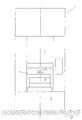
- a press 1 is shown, the Production of the workpieces 2 shown in FIG. 2b from the blanks 3 illustrated in FIG. 2a.
- the press has a stationary table 5, a ram 7 above it on a press stand 6 mounted on the table 5 and movable away from it is.
- the plunger 7 is of a not shown Drive device, such as one Eccentric gear, driven.
- a Forming tool 8 arranged to process the Blanks 3 is used.
- the forming tool 8 includes an individual in 3 to 5 shown lower tool 9 that the table 5 is arranged and one with the plunger 7 connected upper tool 11 is opposite. As from the further description is the lower tool 9 and the upper tool 11 formed so that the Press a blank 3 into one with each working stroke Workpiece 2 formed.
- Fig. 3 The resulting from Fig. 3 and also to the Forming tool 8 belonging upper tool 11 is relative simply trained and consists essentially of the on the plunger 7 attached stamp 13 with a corresponding recess 15 for receiving a molded part or a male 17 for the blank 3 set up is.
- the male 17 is in the area of the blank 3 cylindrical body on its outer peripheral surface is provided with an axial groove that the inner contour of the workpiece to be shaped shown in Fig. 2b 2 corresponds.
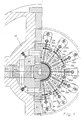
- the lower tool 9 is made of, for example 4 resulting annular frame 19, the one Opening 21 limited.
- the opening 21 is coaxial one defined by the rotationally symmetrical stamp 13 Arranged longitudinal central axis 22. Concentric to the Longitudinal central axis 22 is substantially within the Opening 21 arranged a cage 24 in which a set of Profile rollers 26 each rotatably mounted separately is.
- the profile rollers 26 also go, for example 4 and they are for better distinction each provided with a letter index.
- Each profile roller 26 is divided into two and has one can be brought into engagement with the blank 3 or the workpiece 2, roughly semicircular in side view Profile section 28 and one lying on the opposite side Support section 30 on that for better distinction are also provided with a letter index.
- the profile sections 28 are each in the circumferential direction with a grooved profile that matches that on the workpiece 2 external profile to be trained is complementary.
- Each profile section 28 has a total of three Circumferential ribs, between which two in the circumferential direction running grooves are.
- the profile sections 28 formed such that between two profile sections two adjacent profile rollers 26 a recess is formed, the one to the outside protruding rib of the workpiece 2 to be formed.
- the profile rollers 26 are rotatably mounted on bolts 32, which are held by the cage 24.
- the bolts 32 sit in guides 34 which relate to the cage 24 the longitudinal central axis 22 radially outwards or to the can be moved inside. In the axial direction they are Guides 34, however, essentially with respect to cage 24 kept free of play.
- Abutment serving bearing elements 35 arranged on a side of the profile rollers 26 facing a plane Have tread.
- the profile rollers 26 lie with them Support sections 30 on the treads.
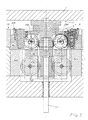
- the bearing elements 35 also have a penetrating the tread Groove on, each housed in a rack 37 is. 3 for a better illustration on the left hand side a past the rack 37 Section through the bearing element 35 and on the right side shown a section of the bearing element 35 cuts in the area of the rack 37 (d).
- the bearing elements are like the profile rollers 26 35 are identical to each other.
- the rack 37 is with a larger longitudinal play stored and on its back with a projection 39 provided with a biased by means of screws Spring means is engaged and from this to one Center position of the rack 37 is too biased.
- Spring means is engaged and from this to one Center position of the rack 37 is too biased.
- the both holding the spring means at each end Bolts allow the middle position to be adjusted.
- each bearing element 35 is beveled on the back and thus wedge-shaped educated. It is supported on a support ring 41, the one on its side facing the bearing element 35 inclined ring surface.
- the axial position of the Bearing element 35 with respect to the support ring 41 is about one at one end on the support ring 41 and at the other end adjusting screw supporting the respective bearing element 35 43 (d, h) set.
- An adjustment of the Adjustment screw 43 (d, h) has an adjustment of the radial position of the corresponding bearing element 35.
- the axial position of the cage 24 is controlled by a gear 45 set that below the profile rollers 26th is arranged.
- the gearbox contains a group of the Profile rollers 26 spaced apart and in the circumferential direction distributed gear wheels 47 (letter index for differentiation), which are rotatably mounted on the cage 24.
- the Gears 47 are stationary, in which Frame 19 arranged racks 51 in engagement.
- the gears 47 with an externally toothed or rack having plunger element 53 that concentrically the longitudinal central axis 22 is arranged.
- the plunger member 53 forming an inner rack goes in on its side facing the upper tool 11 a matrix element 55, referred to as a high-bringer, which is set up for the blank 3 or the workpiece 2 on its face.
- the matrix element 55 is for this purpose optionally with centering means, such as a hole and one in it insertable pin.
- the plunger element 53 stands with a so-called Air bolt 57 in connection, which is coaxial to the longitudinal central axis 22 arranged and by no further shown, preferably pneumatic drive device is arranged in the direction of the longitudinal central axis 22.
- the device 8a described so far works as follows:
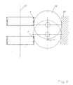
- the blank 3 lies at the beginning of its movement stroke not yet on the profile rollers 26.
- the blank 3 takes the cage 24 with half the ram speed, so that unroll the profile rollers 26 on the bearing elements 35 kick off.
- the diameter of the profile rollers 26 is dimensioned so that these clamp the blank 3 between them and axially Press in the running grooves in the outer circumferential surface.
- the forces that arise are primarily Radial forces supported on the bearing elements 35 become. Remaining axial forces are from the cage 24 recorded and applied by the gear 45. The However, axial forces are considerably smaller than the radial forces.
- the profile rollers 26 are in the in the figures illustrated embodiment in its diameter so dimensioned that with a full stroke of the Stamp 13 by only about 90 °, but in any case less turn as 180 °. They move in the course of this rotation 5 in the position shown, with the the section 3 engaged with the blank 3 the desired groove in the outer peripheral surface of the Introduces blank 3, so that the workpiece 2 obtained becomes.
- the upper tool 11 runs back to its upper dead position, after which the air pin 57 is operated. This lifts the plunger element 53 and that Matrix element 55 again, with the cage 24 in its top dead center runs back.
- the workpiece 3 is made the lower tool 9 pulled out, it now almost free of force or only with little radial force runs along the profile rollers 26. These are through the racks 37 turned back to their desired starting position.
- the Upper tool 11 For forming longitudinal grooves or similar Longitudinal structures in round or otherwise with respect to one Longitudinally shaped housing is made by a Press started with a forming tool 8, the Upper tool 11 a workpiece 2 by a corresponding one Roller arrangement of a lower tool 9 presses.
- the Lower tool 9 has a coaxial to upper tool 11 Opening 21 in which a cage 24 is axially displaceable sits.
- the cage 24 is with a roller group Mistake.
- the rollers are rotatably supported in the cage 24 and are based on radially external, stationary abutments 35 held in the lower tool 9.
- the Rollers are designed and shaped as profile rolls 26 the desired longitudinal structures into the workpiece 3, if this moves between the profile rollers 26 becomes.
- a gear 45 can be provided for longitudinal movement of the cage 24 be, for example, by the cage 24th rotatably mounted gears 47 is formed radially outside on stationary racks 51 and radially inside on a ram 53 provided with toothed racks support that is actuated by the workpiece 3. This Furnishing enables high product quality and high production output at low cost.
Landscapes
- Engineering & Computer Science (AREA)
- Mechanical Engineering (AREA)
- Forging (AREA)
Description
Claims (17)
- Vorrichtung (8) zur Herstellung von Profilen, insbesondere zur Herstellung von Parallelprofilen an rotationssymmetrischen Gehäusen (3),mit einem Oberwerkzeug (11), das an einem Stößel (7) einer Presse (1) befestigbar ist, der gegen eine Werkzeugaufnahme (5) bewegbar ist, und das mit einem zu verformenden Werkstück (3) in und außer Eingriff bringbar ist,mit einem Unterwerkzeug (9), das in Bezug auf den Stößel (7) ortsfest lagerbar ist und das eine Öffnung (21) aufweist, in die das Oberwerkzeug (11) hineinbewegbar ist und deren Achse (22) mit der Bewegungsrichtung des Oberwerkzeuges (11) übereinstimmt,mit einem Satz von Profilrollen (26), die in der Öffnung (21) des Unterwerkzeuges (9) angeordnet sind und deren Außenumfangsflächen mit Widerlagern (35) in Berührung stehen, die die Öffnung (21) begrenzen und die Profilrollen (26) radial nach außen abstützen, wobei die Profilrollen (26) mit ihren Drehachsen in Umfangsrichtung der Öffnung (21) angeordnet sind,mit einem Käfig (24), der in der Öffnung (21) angeordnet ist, an dem die Profilrollen (26) in Umfangsrichtung gehalten sind, der in Axialrichtung (22) der Öffnung (21) bewegbar ist und mittels dessen die Profilrollen (26) bezüglich der Axialrichtung (22) der Öffnung (21) aneinander gefesselt sind, wobei der Käfig (24) mit einem Getriebe (45) verbunden ist, das dazu eingerichtet ist, den Käfig (24) in Axialrichtung (22) und in dieselbe Bewegungsrichtung des Oberwerkzeuges, mit einer Geschwindigkeit anzutreiben, die halb so groß ist, wie die Geschwindigkeit des Oberwerkzeuges (11).
- Vorrichtung nach Anspruch 1, dadurch gekennzeichnet, daß das Getriebe (45) einen in der Öffnungen (21) angeordneten Satz formschlüssiger Getriebemittel (47) enthält, die an ihrer Außenseite mit der Wandung (51) der Öffnung (21) in Verbindung stehen und die an dem Käfig (24) mit in Umfangsrichtung zu der Öffnung (21) orientierten Drehachsen drehbar gelagert sind, und daß die Getriebemittel (47) an ihrer radial innen liegenden Seite mit einem in Axialrichtung (22) der Öffnung (21) bewegbar gelagert angeordneten Kraftübertragungselement (53) in Verbindung stehen.
- Vorrichtung nach Anspruch 3, dadurch gekennzeichnet, daß die formschlüssigen Getriebemittel (47) Zahnräder sind, die mit einer Verzahnung in kämmenden Eingriff stehen, die an dem von dem Oberwerkzeug (11) abliegenden Ende der Öffnung (21) angeordnet ist.
- Vorrichtung nach Anspruch 4, dadurch gekennzeichnet, daß das Kraftübertragungselement (53) an seiner Außenseite eine mit den Zahnrädern (47) in kämmenden Eingriff stehende Verzahnung aufweist.
- Vorrichtung nach Anspruch 3, dadurch gekennzeichnet, daß das Kraftübertragungselement (53) an seiner dem Oberwerkzeug (11) zugewandten Stirnseite zur Aufnahme eines zu verformenden Werkstückes (3) eingerichtet ist.
- Vorrichtung nach Anspruch 1, dadurch gekennzeichnet, daß die Profilrollen (26) an dem Käfig (24) radial verschiebbar gelagert sind.
- Vorrichtung nach Anspruch 1, dadurch gekennzeichnet, daß die Profilrollen (26) einen Durchmesser aufweisen, der wenigstens so groß ist, daß die Profilrollen (26) bei einem Pressenhub weniger als eine halbe Umdrehung vollführen.
- Vorrichtung nach Anspruch 1, dadurch gekennzeichnet, daß die Profilrollen (26) jeweils zweigeteilt sind und an ihrer bezüglich der Öffnung (21) des Unterwerkzeuges (9) radial innen liegenden Seite ein Profil aufweisen, das zu dem an dem Werkstück (3)auszubildenden Profil komplementär ist, sowie an ihrer radial außen liegenden Seite Profil aufweisen, das eine Linienberührung mit den Widerlagern (35) ermöglicht.
- Vorrichtung nach Anspruch 1, dadurch gekennzeichnet, daß die Widerlager (35) in ihrer radialen Einstellung justierbar sind.
- Vorrichtung nach Anspruch 1, dadurch gekennzeichnet, daß die Widerlager (35) in ihrer Neigung bezüglich der Axialrichtung der Öffnung (21) justierbar ausgebildet sind.
- Vorrichtung nach Anspruch 1, dadurch gekennzeichnet, daß an dem Unterwerkzeug (9) Mittel vorgesehen sind, um die Profilrollen (26) hinsichtlich ihrer Drehung bei einem Hub der Vorrichtung (8) in einem festgelegten Winkelbereich zu halten.
- Vorrichtung nach Anspruch 12, dadurch gekennzeichnet, daß die Profilrollen (26) an ihrer bezüglich der Öffnung (21) des Unterwerkzeuges (9) radial außen liegenden Seite mit einer Verzahnung versehen sind, die jeweils mit einer Zahnstange (37) in kämmendem Eingriff stehen.
- Vorrichtung nach Anspruch 13, dadurch gekennzeichnet, daß die Zahnstangen (37) axial verschiebbar gelagert sind.
- Vorrichtung nach Anspruch 14, dadurch gekennzeichnet, daß die Zahnstangen (37) durch Federmittel auf eine unverschobene Mittellage zu vorgespannt sind.
- Verfahren zur Herstellung von Profilen, insbesondere zur Herstellung von Parallelprofilen an rotationssymmetrischen Gehäusen, wobei bei dem Verfahren eine Vorrichtung nach Anspruch 1 zum Einsatz kommt, wobeidas zu verformende Werkstück zwangsbetätigt in eine Öffnung eines Werkzeuges eingeführt wird, in der mittels eines Käfigs gehaltene Profilrollen angeordnet sind, wobei die Rollen derart angeordnet sind, daß sie in Bewegungsrichtung des Werkstückes rollen können,das Werkstück mit den dem Werkstück zugewandten Umfangsabschnitten der Profilrollen in Eingriff gebracht wird, wobei sich die Profilrollen an ihren jeweils diametral gegenüberliegenden Umfangsbereichen innerhalb der Öffnung abstützen,das Werkstück weiter in die Öffnung gedrückt wird, wobei die Profilrollen einerseits an dem Werkstück und andererseits an entsprechenden Widerlagern in Werkstückrichtung abrollen und das Werkstück in seinem Außenbereich verformen.
- Verfahren nach Anspruch 16, dadurch gekennzeichnet, daß der die Rollen haltende Käfig von dem Werkstück über ein Getriebe angetrieben wird.
- Verfahren nach Anspruch 16, dadurch gekennzeichnet, daß das Produkt aus den auf die Rollen einwirkenden und von den Widerlagern aufzunehmenden Radialkräften und den Reibbeiwerten für die Wrkstoffpaarung der Rollen und der Widerlager größer ist als die zum Einführen des Werkstückes erforderliche Axialkraft.
Applications Claiming Priority (2)
| Application Number | Priority Date | Filing Date | Title |
|---|---|---|---|
| DE19531907 | 1995-08-30 | ||
| DE19531907A DE19531907A1 (de) | 1995-08-30 | 1995-08-30 | Vorrichtung und Verfahren zur Herstellung von Profilkörpern |
Publications (2)
| Publication Number | Publication Date |
|---|---|
| EP0761338A1 EP0761338A1 (de) | 1997-03-12 |
| EP0761338B1 true EP0761338B1 (de) | 2001-10-24 |
Family
ID=7770768
Family Applications (1)
| Application Number | Title | Priority Date | Filing Date |
|---|---|---|---|
| EP96113445A Expired - Lifetime EP0761338B1 (de) | 1995-08-30 | 1996-08-22 | Vorrichtung und Verfahren zur Herstellung von Profilkörpern |
Country Status (3)
| Country | Link |
|---|---|
| US (1) | US5794475A (de) |
| EP (1) | EP0761338B1 (de) |
| DE (2) | DE19531907A1 (de) |
Cited By (1)
| Publication number | Priority date | Publication date | Assignee | Title |
|---|---|---|---|---|
| DE102008038127B3 (de) * | 2008-08-18 | 2010-02-04 | Leib, Ulrich, Dr.-Ing. | Verfahren und Vorrichtung zur Herstellung von hochgenauen innen- und außenverzahnten, topfförmigen Blechteilen |
Families Citing this family (10)
| Publication number | Priority date | Publication date | Assignee | Title |
|---|---|---|---|---|
| CA2591958C (en) | 2004-12-23 | 2012-06-19 | Mueller Weingarten Ag | Method for producing longitudinal grooves in cylindrical workpieces |
| DE102006007501A1 (de) * | 2006-02-16 | 2007-08-23 | Müller Weingarten AG | Rollwerkzeug mit integrierter Ziehstufe |
| AT503037B1 (de) | 2006-05-04 | 2007-07-15 | Miba Sinter Austria Gmbh | Verfahren zum herstellen eines zahnrades |
| DE102006025034A1 (de) * | 2006-05-26 | 2007-11-29 | Müller Weingarten AG | Vorrichtung und Verfahren zur Herstellung von Profilkörpern |
| DE102008017608B3 (de) * | 2008-04-06 | 2009-04-30 | Aweba Werkzeugbau Gmbh Aue | Verfahren zur Herstellung eines innen- und außenverzahnten topfförmigen Blechteiles und eine Vorrichtung hierzu |
| DE102008047985A1 (de) * | 2008-09-18 | 2010-03-25 | Webo Werkzeugbau Oberschwaben Gmbh | Vorrichtung und Verfahren zur Herstellung von Längsnuten in zylindrischen Werkstücken |
| DE102013221391A1 (de) * | 2013-10-22 | 2015-04-23 | Allgaier Werke Gmbh | Rollierwerkzeug |
| DE102015009733B4 (de) | 2015-07-31 | 2024-11-28 | Transform Automotive LLC, Inc. | Verfahren zum Rollen von Lamellenträgern oder dergleichen und ein hierzu verwendeter Profilrollensatz |
| US20180036791A1 (en) * | 2016-08-04 | 2018-02-08 | Schaeffler Technologies AG & Co. KG | Tool and method for forming surface features onto a workpiece |
| DE102017119290A1 (de) | 2017-08-23 | 2019-02-28 | Aweba Werkzeugbau Gmbh Aue | Formwerkzeug mit positionierten Zahnprofil-Drückrollen |
Family Cites Families (7)
| Publication number | Priority date | Publication date | Assignee | Title |
|---|---|---|---|---|
| DE2439957A1 (de) * | 1974-08-20 | 1976-03-04 | Grob Kaltwalzmasch Ernst | Verfahren und vorrichtung zum kaltwalzen von parallelen profilen z.b. von zahnprofilen aus dem vollen material |
| US4178790A (en) * | 1978-05-22 | 1979-12-18 | Ex-Cell-O Corporation | Roll-through cold forming apparatus |
| DE2853957A1 (de) * | 1978-12-14 | 1980-07-03 | Karl Fischer | Kochgefaess sowie verfahren und vorrichtung zu seiner herstellung |
| FR2482483A1 (fr) * | 1980-05-14 | 1981-11-20 | Renault | Outil de faconnage par profilage, de cannelures ou de rainures sur des pieces cylindriques en tole |
| CH647430A5 (de) * | 1980-09-19 | 1985-01-31 | Grob Ernst Fa | Vorrichtung und verfahren zum kaltwalzen von profilen durch abwaelzen auf dem umfang eines dabei rotierenden werkstueckes. |
| JP2640835B2 (ja) * | 1988-07-28 | 1997-08-13 | マツダ株式会社 | 板金製スプライン体成形方法および成形工具 |
| CH686817A5 (de) * | 1992-03-04 | 1996-07-15 | Grob Ernst Fa | Vorrichtung und Verfahren zum Herstellen eines wenigstens innen gerade oder schraeg zur Werkstueckachse profilierten hohlen Werkstuecks. |
-
1995
- 1995-08-30 DE DE19531907A patent/DE19531907A1/de not_active Withdrawn
-
1996
- 1996-08-22 DE DE59607991T patent/DE59607991D1/de not_active Expired - Lifetime
- 1996-08-22 EP EP96113445A patent/EP0761338B1/de not_active Expired - Lifetime
- 1996-08-29 US US08/705,497 patent/US5794475A/en not_active Expired - Lifetime
Cited By (1)
| Publication number | Priority date | Publication date | Assignee | Title |
|---|---|---|---|---|
| DE102008038127B3 (de) * | 2008-08-18 | 2010-02-04 | Leib, Ulrich, Dr.-Ing. | Verfahren und Vorrichtung zur Herstellung von hochgenauen innen- und außenverzahnten, topfförmigen Blechteilen |
Also Published As
| Publication number | Publication date |
|---|---|
| EP0761338A1 (de) | 1997-03-12 |
| US5794475A (en) | 1998-08-18 |
| DE19531907A1 (de) | 1997-03-06 |
| DE59607991D1 (de) | 2001-11-29 |
Similar Documents
| Publication | Publication Date | Title |
|---|---|---|
| EP2756893B1 (de) | Materialbearbeitungsvorrichtung, insbesondere eine Umformmaschine | |
| DE2017709A1 (de) | Werkzeug zum Einrollen von Längsnuten in zylindrische Werkstücke | |
| EP2781280B1 (de) | Verfahren zur Herstellung einer Stauchniet-Verbindung mit einer rotativen Pendelbewegung | |
| DE3110221A1 (de) | Stanzpresse | |
| DE19639081C2 (de) | Vorrichtung zum Herstellen eines Werkstücks mit einer zylindrischen profilierten Wand | |
| DE102009044544B4 (de) | Umformvorrichtung und Einrichtverfahren zum Einbringen einer Innen- und Außenverzahnung in ein zylindrisches Werkstück | |
| DE2419854C3 (de) | Verfahren und Drückmaschine zum Herstellen einer mehrrilligen Keilriemenscheibe aus Blech | |
| EP2127777A1 (de) | Vorrichtung und Verfahren zum Herstellen oder Bearbeiten von Werkstücken aus einer Vorform, insbesondere zum Anformen von Innenprofilen oder Innenverzahnungen | |
| EP0761338B1 (de) | Vorrichtung und Verfahren zur Herstellung von Profilkörpern | |
| EP0163922A2 (de) | Automat für die hydroplastische Bearbeitung von Stirnrädern | |
| EP0611612B1 (de) | Drückwalzmschine | |
| EP0017660A1 (de) | Hydraulikpresse | |
| EP0955110B1 (de) | Verfahren zum Drückwalzen und Drückwalzvorrichtung | |
| EP0425994A2 (de) | Verfahren und Maschine zum Abstechen von Rohren und gegebenenfalls Anfasen der hierbei gebildeten Rohrstirnkanten | |
| DE3327258C2 (de) | ||
| DE2810273C2 (de) | Vorrichtung zur Regelung der Vorschubgeschwindigkeit des Dorns in einem kontinuierlichen, mit gehaltenem Dorn arbeitenden Walzwerk | |
| DE69211654T2 (de) | Vorrichtung und verfahren zum kaltformen von nuten in die wandung eines rotationskörpers | |
| EP3159068B1 (de) | Umformmaschine zum drücken/drückwalzen und verfahren zum drücken/drückwalzen | |
| DE2340125C3 (de) | Maschine zum Profilwalzen, insbesondere Kaltwalzen von Walzlageraußenringen | |
| EP0917917A1 (de) | Verfahren und Vorrichtung zum Kaltumformen von Hohlteilen | |
| EP3060359B2 (de) | Rollierwerkzeug | |
| EP2165785B1 (de) | Vorrichtung und Verfahren zur Herstellung von Längsnuten in zylindrischen Werkstücken | |
| DE102008038127B3 (de) | Verfahren und Vorrichtung zur Herstellung von hochgenauen innen- und außenverzahnten, topfförmigen Blechteilen | |
| DE19636567C2 (de) | Verfahren zum Drückwalzen eines Getriebeteiles mit einer Innenverzahnung | |
| EP3414030B1 (de) | Walzvorrichtung zum walzen von werkstücken mit verzahnung und zugehöriges verfahren |
Legal Events
| Date | Code | Title | Description |
|---|---|---|---|
| PUAI | Public reference made under article 153(3) epc to a published international application that has entered the european phase |
Free format text: ORIGINAL CODE: 0009012 |
|
| AK | Designated contracting states |
Kind code of ref document: A1 Designated state(s): CH DE FR GB IT LI SE |
|
| 17P | Request for examination filed |
Effective date: 19970826 |
|
| RAP1 | Party data changed (applicant data changed or rights of an application transferred) |
Owner name: SCHULER PRESSEN GMBH & CO. KG |
|
| 17Q | First examination report despatched |
Effective date: 20000329 |
|
| GRAG | Despatch of communication of intention to grant |
Free format text: ORIGINAL CODE: EPIDOS AGRA |
|
| GRAG | Despatch of communication of intention to grant |
Free format text: ORIGINAL CODE: EPIDOS AGRA |
|
| GRAH | Despatch of communication of intention to grant a patent |
Free format text: ORIGINAL CODE: EPIDOS IGRA |
|
| GRAH | Despatch of communication of intention to grant a patent |
Free format text: ORIGINAL CODE: EPIDOS IGRA |
|
| GRAA | (expected) grant |
Free format text: ORIGINAL CODE: 0009210 |
|
| AK | Designated contracting states |
Kind code of ref document: B1 Designated state(s): CH DE FR GB IT LI SE |
|
| REG | Reference to a national code |
Ref country code: CH Ref legal event code: EP |
|
| REF | Corresponds to: |
Ref document number: 59607991 Country of ref document: DE Date of ref document: 20011129 |
|
| REG | Reference to a national code |
Ref country code: CH Ref legal event code: NV Representative=s name: CABINET ROLAND NITHARDT CONSEILS EN PROPRIETE INDU |
|
| REG | Reference to a national code |
Ref country code: GB Ref legal event code: IF02 |
|
| GBT | Gb: translation of ep patent filed (gb section 77(6)(a)/1977) |
Effective date: 20020105 |
|
| ET | Fr: translation filed | ||
| PLBE | No opposition filed within time limit |
Free format text: ORIGINAL CODE: 0009261 |
|
| STAA | Information on the status of an ep patent application or granted ep patent |
Free format text: STATUS: NO OPPOSITION FILED WITHIN TIME LIMIT |
|
| 26N | No opposition filed | ||
| PGFP | Annual fee paid to national office [announced via postgrant information from national office to epo] |
Ref country code: GB Payment date: 20030729 Year of fee payment: 8 |
|
| PGFP | Annual fee paid to national office [announced via postgrant information from national office to epo] |
Ref country code: FR Payment date: 20030819 Year of fee payment: 8 |
|
| PGFP | Annual fee paid to national office [announced via postgrant information from national office to epo] |
Ref country code: SE Payment date: 20030826 Year of fee payment: 8 Ref country code: CH Payment date: 20030826 Year of fee payment: 8 |
|
| PG25 | Lapsed in a contracting state [announced via postgrant information from national office to epo] |
Ref country code: GB Free format text: LAPSE BECAUSE OF NON-PAYMENT OF DUE FEES Effective date: 20040822 |
|
| PG25 | Lapsed in a contracting state [announced via postgrant information from national office to epo] |
Ref country code: SE Free format text: LAPSE BECAUSE OF NON-PAYMENT OF DUE FEES Effective date: 20040823 |
|
| PG25 | Lapsed in a contracting state [announced via postgrant information from national office to epo] |
Ref country code: LI Free format text: LAPSE BECAUSE OF NON-PAYMENT OF DUE FEES Effective date: 20040831 Ref country code: CH Free format text: LAPSE BECAUSE OF NON-PAYMENT OF DUE FEES Effective date: 20040831 |
|
| EUG | Se: european patent has lapsed | ||
| GBPC | Gb: european patent ceased through non-payment of renewal fee |
Effective date: 20040822 |
|
| REG | Reference to a national code |
Ref country code: CH Ref legal event code: PL |
|
| PG25 | Lapsed in a contracting state [announced via postgrant information from national office to epo] |
Ref country code: FR Free format text: LAPSE BECAUSE OF NON-PAYMENT OF DUE FEES Effective date: 20050429 |
|
| REG | Reference to a national code |
Ref country code: FR Ref legal event code: ST |
|
| PG25 | Lapsed in a contracting state [announced via postgrant information from national office to epo] |
Ref country code: IT Free format text: LAPSE BECAUSE OF NON-PAYMENT OF DUE FEES;WARNING: LAPSES OF ITALIAN PATENTS WITH EFFECTIVE DATE BEFORE 2007 MAY HAVE OCCURRED AT ANY TIME BEFORE 2007. THE CORRECT EFFECTIVE DATE MAY BE DIFFERENT FROM THE ONE RECORDED. Effective date: 20050822 |
|
| PGFP | Annual fee paid to national office [announced via postgrant information from national office to epo] |
Ref country code: DE Payment date: 20120726 Year of fee payment: 17 |
|
| PG25 | Lapsed in a contracting state [announced via postgrant information from national office to epo] |
Ref country code: DE Free format text: LAPSE BECAUSE OF NON-PAYMENT OF DUE FEES Effective date: 20140301 |
|
| REG | Reference to a national code |
Ref country code: DE Ref legal event code: R119 Ref document number: 59607991 Country of ref document: DE Effective date: 20140301 |