EP0759111B1 - Schwingboden - Google Patents
Schwingboden Download PDFInfo
- Publication number
- EP0759111B1 EP0759111B1 EP96907428A EP96907428A EP0759111B1 EP 0759111 B1 EP0759111 B1 EP 0759111B1 EP 96907428 A EP96907428 A EP 96907428A EP 96907428 A EP96907428 A EP 96907428A EP 0759111 B1 EP0759111 B1 EP 0759111B1
- Authority
- EP
- European Patent Office
- Prior art keywords
- springy
- load distribution
- reinforcing ribs
- floor according
- range
- Prior art date
- Legal status (The legal status is an assumption and is not a legal conclusion. Google has not performed a legal analysis and makes no representation as to the accuracy of the status listed.)
- Expired - Lifetime
Links
- 230000003014 reinforcing effect Effects 0.000 claims abstract description 52
- 239000002023 wood Substances 0.000 claims description 14
- 239000000463 material Substances 0.000 claims description 9
- 239000010410 layer Substances 0.000 claims 3
- 238000004026 adhesive bonding Methods 0.000 claims 2
- 150000001875 compounds Chemical class 0.000 claims 2
- 230000015572 biosynthetic process Effects 0.000 claims 1
- 239000002365 multiple layer Substances 0.000 claims 1
- 230000002787 reinforcement Effects 0.000 description 10
- 238000010276 construction Methods 0.000 description 7
- 230000008901 benefit Effects 0.000 description 6
- 238000005516 engineering process Methods 0.000 description 4
- 238000011161 development Methods 0.000 description 3
- 230000018109 developmental process Effects 0.000 description 3
- 239000000969 carrier Substances 0.000 description 2
- 239000011093 chipboard Substances 0.000 description 2
- 238000009434 installation Methods 0.000 description 2
- 239000011120 plywood Substances 0.000 description 2
- 230000003068 static effect Effects 0.000 description 2
- 230000009286 beneficial effect Effects 0.000 description 1
- 230000015556 catabolic process Effects 0.000 description 1
- 230000000295 complement effect Effects 0.000 description 1
- 238000013016 damping Methods 0.000 description 1
- 230000000694 effects Effects 0.000 description 1
- 230000002349 favourable effect Effects 0.000 description 1
- 238000009408 flooring Methods 0.000 description 1
- 238000005259 measurement Methods 0.000 description 1
- 210000002346 musculoskeletal system Anatomy 0.000 description 1
- 239000002985 plastic film Substances 0.000 description 1
- 229920006255 plastic film Polymers 0.000 description 1
- 230000011218 segmentation Effects 0.000 description 1
- 125000006850 spacer group Chemical group 0.000 description 1
- 238000005728 strengthening Methods 0.000 description 1
Images



Classifications
-
- E—FIXED CONSTRUCTIONS
- E04—BUILDING
- E04F—FINISHING WORK ON BUILDINGS, e.g. STAIRS, FLOORS
- E04F15/00—Flooring
- E04F15/22—Resiliently-mounted floors, e.g. sprung floors
Definitions
- the invention relates to an elastic, multi-layer Schwingboden, such as a sports or multi-purpose hall floor, according to the preamble of the claim 1.
- a sports floor must be proportionate strict criteria regarding power loss meet, so risks when loading the musculoskeletal system of the athlete are kept small.
- the static and dynamic deformation behavior of the swinging floor largely through the Structure and support of the vibrating beams determined.
- these are double swing beams formed, in which two resilient plies stand vertically above each other and through spacers in longitudinal spacing in be kept at a predetermined distance.
- the lower webbing layer in turn is supported by support supports, which are also at a predetermined lateral distance from each other stand.
- load distribution plates will be So far in standard dimensions with a width between about 1.0 m to 3.0 m and lengths up to 4.5 m used, while usually the side distance of the substructure of the swinging floor forming double swinging beam is usually much smaller, for example is between 0.4 and 0.6 m.
- the invention is therefore based on the object elastic, multilayered swinging floor according to the generic term of claim 1 so that itself while maintaining a simple assembly the surface of the swinging floor is even Vibration and damping behavior sets.
- the invention is based on the knowledge that the deflection trough in the direction transverse to the longitudinal extension of the Vibration carrier tends to be larger than the other Direction of measurement, i.e. in the direction parallel to the vibrating beams.
- the load distribution layer manages to Deflection trough in the direction transverse to the swing beams not just to keep it smaller, but to keep it over to additionally influence the width of the segments that it becomes approximately the same in both measuring directions.
- the length of the load distribution segments can vary be kept very large as before, for example in Range up to 4.5 m.
- the area of the load distribution plate segments can therefore be compared to the previous used load distribution plates approximately on comparable Level are maintained so that the assembly effort when laying the Schwingêt not noticeably enlarged.
- the blind floor board layer is preferably corresponding the training according to claim 5 trained and integrated in the load distribution plates. With this Further training gives the possibility of assembly of the load distribution plate modules on the vibrating beams providing a good flush of the contiguous Modules. It is an advantage that Load distribution plates together with the underlying, end portions protruding from the mounting dimension the reinforcing ribs with the top flange of the To connect the vibrating support firmly, preferably to screw it together. In this way, it is enough to connect the load distribution layer with the vibrating beams only over every other reinforcement rib, whereby Assembly time is saved.
- the reinforcing ribs are at both ends cut at an angle, with the protruding end faces and the recessed end faces on one Side of the load distribution module parallel to each other run, but are cut in opposite directions, so that they complement each other when laying the modules Put the designed end faces together in a form-fitting manner.
- the vibrating beam can be wide of the top chord can be reduced.
- Position fixation can be used.
- the opposite cut End faces of the respective adjacent protruding and recessed reinforcement ribs a kind of centering function that the assembly designed safer and simpler.
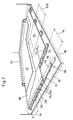
- An elastic, multilayered swinging base is supported on a concrete layer 120 with an overlying seal 122 onwards.
- the reference numeral 130 are double swing beams designated, the predetermined parallel distance PA are laid to each other and in assembly units of about 4 m, for example.
- the Double swing beams 130 are supported in turn Support bearing 114 on the base 120, 122.
- the Longitudinal distance of the support bearing 114 is designated LA.
- both upper belt board layer 110 and the lower belt board layer 112 trained throughout.
- the connection between upper and lower belt board layer 110, 112 takes place by means of a series of intermediate pieces 116, which at offset to the embodiment shown the support supports 114 are.
- the intermediate pieces 116 Like the support supports 114, they are cuboid Bodies formed and are preferably made of wood or. Wood material. They are both with the lower flange as well as firmly connected to the top chord, preferably screwed and / or clamped.
- the swinging floor is one Dummy floor board layer 124 which is a load distribution layer in the form of load distribution plates 132 wearing.
- the load distribution plates 132 are preferred made of chipboard or plywood.
- Above the load distribution layer in the form of the load distribution plates Finally, 132 rests with the interposition a thin plastic film 126 with the Reference number 131 designated top covering.
- the side Security bar is labeled 133. It forms the side closure of the swinging floor.
- the load distribution plates 132 are strip-shaped or subdivided, the width B132 of the resulting emerging load distribution plate segments at most is kept large as the parallel distance PA between adjacent swing beams 130.
- the lengths L132 of Load distribution plate segments 132 are preferably a multiple of the width B132. For example, it will in a length range between 3.0 and 4.1 m.
- This new subdivision of the load distribution layer 132 can the deflection trough, in particular the dimension "W500" according to DIN 18032 part 2 in the equalize both measuring directions I and II (see Figure 1).
- the deflection trough can be in measuring direction II, i.e. in the direction Reduce transverse to the longitudinal extent of the swing bracket 130 and adjust using dimension B132.
- FIG. 2 A slightly modified embodiment of the swinging floor is shown in Figure 2.
- load sharing layer 132 with the Blind floor board layer 134 combined into modules.
- FIG. 2 shows a schematic plan view of a Swing floor with load distribution plates laid on swing beams.
- the vibrating beams have the reference symbol 130 and are indicated by dash-dotted lines. These vibration carriers 130 are at a parallel distance PA of 500 mm for example.
- the support supports 14 are the swing beams 130 not shown in detail.
- the arrangement is in the Usually taken so that the lateral distance of the Support bearing 14 essentially the parallel distance PA laterally adjacent vibration carrier 130 corresponds.
- the adjacent vibration carriers 130 are laid in such a way that the support bearing of a swing beam in essentially offset to the center of the support supports stand adjacent vibrating beam.
- the width of the The vibrating beam is labeled B.
- a load distribution module 132 denotes the shape of an elongated rectangle has a width B132 and a length L132.
- the Width B132 corresponds to the parallel distance PA of neighboring Schwingong 130.
- the length corresponds to L132 at least dimension B132, but it is preferably a multiple thereof.
- a width of the preferred length dimension L132 is about 500 mm with a length of up to 4500 mm.
- FIG. 2 Another peculiarity of the load distribution layer according to Figure 2 is that the load distribution plates 132 on the bottom with a multitude of reinforcing ribs 134 are equipped.
- the reinforcement ribs 134 thus fulfill the function of a Blind floor board layer, so that, according to the invention, load distribution modules are used in which the Blind floor board layer integrated in the load distribution layer is.
- the reinforcing ribs 134 are made of wood or Wood material and they have a length L134 which the Width B132 corresponds to the load distribution plate 132. Adjacent reinforcing ribs 134 are in alternation with one another so offset that they alternate between different ones Pages around a predetermined mounting dimension MMV protrude or lag one assembly dimension MMZ.
- the reinforcing ribs can preferably be of variable thickness in the range between 12 and 30 mm or with variable width B134 in the range between 30 and 150 mm be trained.
- the clear lateral distance between adjacent reinforcing ribs 134 are preferably located in the range between 0 and 100 mm, depending on the load profile of the swing floor to be manufactured.
- the load distribution modules 132 are mounted on the following way:
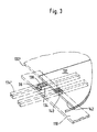
- Figures 2 and 3 show that the reinforcing ribs 134 on both sides on the top chords 110 support the swing arm 130.
- Lines in Figure 8 is a support surface 36 for the reinforcing rib 134 provided by the side of the Load distribution module lags.
- These load balancing modules are laid so that the End face of the reinforcement rib 134 is the reinforcement rib 134 'of the load distribution module 132', preferably a small assembly gap leaded.
- 138 and 140 hatched areas are supporting and connecting surfaces over which the connection the load distribution plates 132 with the top chord 110 takes place.
- These support and connecting surfaces 138, 140 are mutually on both sides of the butt line 142 adjacent load distribution plates 132, 132 'are arranged, and the connection is made with the help of connecting screws and / or connecting clips and / or connecting nails in a zigzag pattern in the essentially through the center of the support and connecting surfaces 138, 140 from the top of the load distribution plates 132, 132 'are struck here.
- the load distribution plates 132 with attached preferably screwed and / or clamped and / or glued-on reinforcing ribs 134 are used as pre-assembled modules delivered to the construction site and can quickly get there on the pre-aligned vibrating beam 130 can be installed.
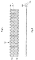
- FIGs 4 and 5 are details of the load distribution plate modules shown in Figures 2 and 3.
- the thickness D132 of the load distribution plate 132 only a fraction of the thickness D134 of the reinforcing ribs 134 matters. It is also from the illustration recognizable according to FIG. 4 that the according to FIG reinforcement rib on the far right side 134 * half across the face 144 protrudes and thus the impact to the adjacent load distribution plate 132 bridges.
- Figure 4 shows how the connection between the reinforcing ribs 134 and the load distribution plate 132 is realized.
- the reference numerals 146 are designated attachment points at which the Reinforcing ribs 134 with the load distribution plate 132 are screwed.
- the load distribution plates 232 have a bottom Variety of reinforcing ribs 234 equipped.
- the reinforcing ribs 234 thus fulfill the function a blind floor board layer, so that the blind floor board layer is integrated in the load distribution layer.
- the reinforcing ribs 234 are made of wood or Wood material and they have a length L234 which is essentially the width B232 of the load distribution plate 232 corresponds. Adjacent reinforcing ribs 234A, B are alternately offset from each other so that they alternate from different sides of module 232 um project a predetermined assembly dimension MMV or around Installation dimension MMZ back.
- the reinforcing ribs can be of variable thickness preferably in the range between 12 and 30 mm or with variable width B234 in the range between 30 and 150 mm be trained.
- the clear lateral distance between adjacent reinforcing ribs 234 are preferably located in the range between 0 and 100 mm, depending on the load profile of the swing floor to be manufactured.
- the load distribution plates 232 with attached, preferably screwed and / or clamped and / or glued-on reinforcing ribs 234 are used as pre-assembled modules delivered to the construction site and can quickly get there on the pre-aligned vibrating beam 230 can be installed.
- the thickness D232 of the load distribution plate 232 is only a fraction of the thickness D234 of the reinforcing ribs 234.
- Figure 8 shows how the connection between the reinforcing ribs 234 and the load distribution plate 232 is realized.
- Fastening points 246 are indicated at which the reinforcing ribs 234 with the load distribution plate 232 are screwed.
- Adjacent reinforcing ribs 234A, 234B are alternately offset from each other so that they alternate from different sides around a predetermined one Project assembly dimensions MMV or lag one assembly dimension MMZ.
- the reinforcing ribs 234, however, are not cut straight, but cut diagonally, so that end faces 260 arise that to the longitudinal edge 262 of the load distribution module 232 in one predetermined, oblique angle.
- Figure 9 and 10 are the adjacent reinforcing ribs, that alternate on one side and stand back, designated 234A and 234B, the End faces have been given the reference numbers 260A and 260B. It can be seen that the end faces 260A, 260B adjacent reinforcing ribs 234A, 234B in opposite directions are cut, but the angle that the corresponding end face 260 with the longitudinal edge 262 includes the same absolute amount, but different Has a sign.
- the assembly takes place - as shown in FIG. 10 - in such a way that when connecting a load distribution module 232 ' in addition to the load distribution module 232, the bottom side Continue reinforcing ribs 234 'and 234 in alignment. If the position is exact, the lateral ones come End faces 260 and 260 'almost flat against each other to lie, with a small assembly gap MS remains.
- the opposite cut of the end faces 260th adjacent reinforcing ribs 234 have a self-centering effect causes the advantages of assembly technology Has.
- the neighboring load distribution modules 232 ', 232 no longer moved along the edge 262 become.
- the areas 238 are hatched in FIG. Drawn 240, via which the connection of the load distribution plates 232 with the top chord 210.
- At 236 is the support surface over which there is a reinforcing rib 234 'of the neighboring module on the top chord 210 can support.
- the invention thus creates an elastic, multi-layer Schwingboden, for example in the design as a sports floor, with a variety of im lateral parallel distance to each other Vibration supports on which are aligned across them Blind bottom board layer load distribution plates support.
- the load distribution plates are of such a type subdivided into strips that load distribution plate segments with a maximum width of lateral distance between neighboring, below Result in vibrating beams.
- the swinging floor can further improve the Ease of installation a special design of the Have reinforcement ribs on the load distribution modules.
- the Reinforcing ribs are at both ends cut at an angle, with the protruding end faces and the recessed end faces on one side of the Load distribution module run parallel to each other, however are cut in opposite directions, so that they are flush and flush when laying the modules, i.e. form-fit each other. So that at predetermined bearing surface for the reinforcing ribs on the vibrating beam below, the width of the Swing beam or the width of the top chord of the Vibration carrier can be reduced. It also results a centering function due to the reinforcing ribs during assembly so that assembly inaccuracies are effective be excluded.
Landscapes
- Engineering & Computer Science (AREA)
- Architecture (AREA)
- Civil Engineering (AREA)
- Structural Engineering (AREA)
- Floor Finish (AREA)
Description
- Fig. 1
- eine zum Teil aufgebrochene perspektivische Ansicht eines elastischen, mehrlagigen Schwingbodens;
- Fig. 2
- eine schematische Draufsicht auf eine etwas modifizierte Ausführungsform des Schwingbodens;
- Fig. 3
- eine schematische, perspektivische Ansicht einer Einzelheit des in Figur 2 gezeigten Schwingbodens zur Verdeutlichung des Montage-bzw. Verlegeprinzips der Lastverteilungsplattensegmente auf dem Schwingträger;
- Fig. 4
- eine Ansicht der bei der Ausführungsform gemäß Figur 2 verwendeten Lastverteilungsplattensegmente von unten;
- Fig. 5
- die Ansicht des Lastverteilungsplattensegments gemäß Figur 4 bei einer Blickrichtung entsprechend "V" in Figur 4;
- Fig. 6 bis 8
- Ansichten des beim Schwingboden gemäß Fig. 1 verwendeten Lastverteilungsmoduls;
- Fig. 9
- eine schematische, perspektivische Ansicht einer Einzelheit des Schwingbodens zur Verdeutlichung des Montage- bzw. Verlegeprinzips der Lastverteilungsplattensegmente auf dem Schwingträger; und
- Fig. 10
- eine schematische Detailansicht im Bereich einer Trennfuge zweier benachbarter Lastverteilungsmodule zur Verdeutlichung der montagetechnischen Vorteile der vorliegenden Erfindung.
Claims (20)
- Elastischer mehrlagiger Schwingboden, wie z.B. Sportboden, mit einer Vielzahl von im seitlichen Parallelabstand zueinander liegenden Schwingträgern, vorzugsweise Doppelschwingträgern (130; 230).,auf denen sich über eine quer dazu ausgerichtete Blindbodenbrettlage (134; 234) Lastverteilungsplatten abstützen, dadurch gekennzeichnet, daß die Lastverteilungsplatten (132; 132'; 232; 232') derart streifenförmig untergliedert sind, daß sich Lastverteilungsplattensegmente mit einer maximalen Breite (B132; B232) des seitlichen Abstandes (PA) benachbarter, darunterliegender Schwingträger (130; 230) ergeben.
- Schwingboden nach Anspruch 1, dadurch gekennzeichnet, daß die Untergliederung längs der Mittellinie der darunterliegenden Schwingträger (130; 230) vorgenommen ist.
- Schwingboden nach Anspruch 2, dadurch gekennzeichnet, daß die Lastverteilungsplatten (132; 232) mit Komponenten der Blindbodenbrettlage (134; 134'; 234; 234') zu Modulen (132; 132'; 232; 232') verbunden sind.
- Schwingboden nach Anspruch 3, dadurch gekennzeichnet, daß die Breite (B132; B232) der Module im wesentlichen dem Parallelabstand (PA) benachbarter Schwingträger(130; 230) entspricht.
- Schwingboden nach einem der Ansprüche 1 bis 4, dadurch gekennzeichnet, daß die Lastverteilungsplatte (132; 232) auf ihrer Unterseite eine Vielzahl von Verstärkungsrippen (134; 234) trägt, die quer zur Längserstreckung der Lastverteilungsplatte (132; 232) verlaufen und abwechselnd von den beiden Seitenrändern (142; 242) um ein vorbestimmtes Montagemaß (MMV und MMZ) vorstehen bzw. zurückstehen, wodurch sich ein verzahnendes Ineinandergreifen der Verstärkungsrippen (134; 134'; 234; 234') benachbarter Lastverteilungsplatten (132; 132'; 232; 232') ergibt.
- Schwingboden nach einem der Ansprüche 1 bis 5, dadurch gekennzeichnet, daß die Verstärkungsrippen (134; 234) an ihren beiden Enden jeweils schräg angeschnitten sind, wobei die vorstehenden Endflächen (260B) und die zurückgesetzten Endflächen (260A) jeweils auf einer Seite des Lastverteilungsmoduls (132; 232) jeweils zueinander parallel verlaufen, jedoch gegensinnig angeschnitten sind, so daß sie sich beim Verlegen der Module (132; 232; 132'; 232') formschlüssig aneinanderlegen.
- Schwingboden nach einem der Ansprüche 1 bis 6, dadurch gekennzeichnet, daß die Lastverteilungsplatte (132; 232) aus einem Holzwerkstoff oder einem Verbund von vorzugsweise geschichteten Holzwerkstoffen besteht.
- Schwingboden nach einem der Ansprüche 5 bis 7, dadurch gekennzeichnet, daß die Verstärkungsrippen (134; 134'; 234; 234') aus Holz oder Holzwerkstoff bestehen und mit der Lastverteilungsplatte (132; 132'; 232; 232') verschraubt und/oder verklammert und/oder verleimt sind.
- Schwingboden nach Anspruch 8, dadurch gekennzeichnet, daß die Verstärkungsrippen (134; 234) eine Länge (L134; L234) im Bereich zwischen 250 und 1000 mm, eine Breite (B134; B234) im Bereich zwischen 30 und 150 mm und eine Stärke im Bereich zwischen 12 und 30 mm haben.
- Schwingboden nach einem der Ansprüche 5 bis 9, dadurch gekennzeichnet, daß die Verstärkungsrippen (134; 234) einen seitlichen Abstand bis zu etwa 100 mm voneinander haben.
- Schwingboden nach einem der Ansprüche 1 bis 10, dadurch gekennzeichnet, daß die Lastverteilungsplatten (132; 232) eine Breite (B132; B232) im Bereich zwischen 250 und 1000 mm, eine Länge (L132; L232) im Bereich zwischen 400 und 4500 mm und eine Stärke im Bereich zwischen 6 und 25 mm haben.
- Schwingboden nach einem der Ansprüche 5 bis 11, dadurch gekennzeichnet, daß die Module (132; 232) mit den Schwingträgern (130; 230) im Bereich der seitlichen Vorsprünge (138; 238) der Verstärkungsrippen (134; 234) verbunden, vorzugsweise verschraubt, verklammert oder vernagelt sind.
- Schwingboden nach einem der Ansprüche 1 bis 12, dadurch gekennzeichnet, daß die Lastverteilungsplatten (132; 232) jeweils Bestandteil eines Lastverteilungsplattenmoduls sind, dessen Breite (B132; B232) im wesentlichen dem Parallelabstand der Schwingträger von Mitte zu Mitte entspricht und in dem die Gurtbrettlage integriert ist.
- Schwingboden nach Anspruch 13, dadurch gekennzeichnet, daß die Lastverteilungsplatte (132; 232) auf ihrer Unterseite eine Vielzahl von Verstärkungsrippen (134; 234) trägt, die quer zur Längserstreckung der Lastverteilungsplatte (132; 232) verlaufen und abwechselnd von beiden Seitenrändern (142) um ein vorbestimmtes Montagemaß (MMV und MMZ) vorstehen bzw. zurückstehen, wodurch sich ein verzahnendes Ineinandergreifen der Verstärkungsrippen (134; 134'; 234; 234') benachbarter Lastverteilungsplatten (132; 132'; 232; 232') ergibt.
- Schwingboden nach einem der Ansprüche 13 oder 14, dadurch gekennzeichnet, daß die Verstärkungsrippen (134; 234) an ihren beiden Enden jeweils schräg angeschnitten sind, wobei die vorstehenden Endflächen (260B) und die zurückgesetzten Endflächen (260A) jeweils auf einer Seite des Lastverteilungsmoduls (132; 232) jeweils zueinander parallel verlaufen, jedoch gegensinnig angeschnitten sind, so daß sie sich beim Verlegen der Module (132; 232; 132'; 232') formschlüssig aneinanderlegen.
- Schwingboden nach einem der Ansprüche 13 bis 15, dadurch gekennzeichnet, daß die Lastverteilungsplatte (132; 232) aus einem Holzwerkstoff oder einem Verbund von vorzugsweise geschichteten Holzwerkstoffen besteht.
- Schwingboden nach einem der Ansprüche 14 bis 16, dadurch gekennzeichnet, daß die Verstärkungsrippen (134; 134'; 234; 234') aus Holz oder Holzwerkstoff bestehen und mit der Lastverteilungsplatte (132; 132'; 232; 232') verschraubt und/oder verklammert und/oder verleimt sind.
- Schwingboden nach Anspruch 17, dadurch gekennzeichnet, daß die Verstärkungsrippen (134; 234) eine Länge (L134; L234) im Bereich zwischen 250 und 1000 mm, eine Breite (B134; B234) im Bereich zwischen 30 und 150 mm und eine Stärke im Bereich zwischen 12 und 30 mm haben.
- Schwingboden nach einem der Ansprüche 14 bis 18, dadurch gekennzeichnet, daß die Verstärkungsrippen (134; 234) einen seitlichen Abstand bis zu etwa 100 mm voneinander haben.
- Schwingboden nach einem der Ansprüche 13 bis 19, dadurch gekennzeichnet, daß die Lastverteilungsplatten (132; 232) eine Breite (B132; B232) im Bereich zwischen 250 und 1000 mm, eine Länge (L132; L232) im Bereich zwischen 400 und 4500 mm und eine Stärke im Bereich zwischen 6 und 25 mm haben.
Applications Claiming Priority (5)
| Application Number | Priority Date | Filing Date | Title |
|---|---|---|---|
| DE19508463 | 1995-03-09 | ||
| DE19508463A DE19508463A1 (de) | 1995-03-09 | 1995-03-09 | Schwingboden |
| DE19532607 | 1995-09-04 | ||
| DE19532607A DE19532607A1 (de) | 1995-03-09 | 1995-09-04 | Schwingboden |
| PCT/EP1996/001036 WO1996028626A1 (de) | 1995-03-09 | 1996-03-11 | Schwingboden |
Publications (2)
| Publication Number | Publication Date |
|---|---|
| EP0759111A1 EP0759111A1 (de) | 1997-02-26 |
| EP0759111B1 true EP0759111B1 (de) | 2001-07-11 |
Family
ID=26013209
Family Applications (1)
| Application Number | Title | Priority Date | Filing Date |
|---|---|---|---|
| EP96907428A Expired - Lifetime EP0759111B1 (de) | 1995-03-09 | 1996-03-11 | Schwingboden |
Country Status (3)
| Country | Link |
|---|---|
| EP (1) | EP0759111B1 (de) |
| AT (1) | ATE203083T1 (de) |
| WO (1) | WO1996028626A1 (de) |
Family Cites Families (4)
| Publication number | Priority date | Publication date | Assignee | Title |
|---|---|---|---|---|
| DE1907190A1 (de) * | 1969-02-13 | 1970-08-27 | Hoess Klaus Dieter | Elastischer Fussboden |
| DE8329011U1 (de) * | 1983-10-07 | 1984-01-26 | Hamberger Industriewerke Gmbh, 8200 Rosenheim | Schwingtraeger fuer einen sporthallenboden |
| DE3838712A1 (de) * | 1988-11-15 | 1990-05-17 | Osterwald Sportboden Gmbh | Schwingboden |
| FI347U1 (fi) * | 1992-06-24 | 1992-10-28 | Vaeaenaenen Oy H | Elastisk golvkonstruktion |
-
1996
- 1996-03-11 AT AT96907428T patent/ATE203083T1/de not_active IP Right Cessation
- 1996-03-11 EP EP96907428A patent/EP0759111B1/de not_active Expired - Lifetime
- 1996-03-11 WO PCT/EP1996/001036 patent/WO1996028626A1/de not_active Ceased
Also Published As
| Publication number | Publication date |
|---|---|
| EP0759111A1 (de) | 1997-02-26 |
| WO1996028626A1 (de) | 1996-09-19 |
| ATE203083T1 (de) | 2001-07-15 |
Similar Documents
| Publication | Publication Date | Title |
|---|---|---|
| DE2221761C3 (de) | Schwingboden | |
| DE3707305A1 (de) | Elastische platte fuer schienengleiche bahnuebergaenge | |
| DE202004015275U1 (de) | Paneel, insbesondere Fußbodenpaneel | |
| WO2004018798A2 (de) | Fussboden aus einzelnen elementen | |
| DE68917889T2 (de) | Befestigung für Schienen. | |
| WO1998000617A2 (de) | Bauteilvorrichtung für decken, wände, bedachungen oder dgl. | |
| EP0716198B1 (de) | Vorrichtung zum Befestigen von Fassadenplatten | |
| EP1538276B1 (de) | Fussbodenpaneel | |
| AT401791B (de) | Verbundplatte mit wenigstens einer deckschicht aus holz | |
| DE202006006672U1 (de) | Einrichtung zur Befestigung von Brettern | |
| EP0916779A1 (de) | System zur Herstellung von Stelzen für Belagsaufbauten aus Platten auf Terrassen, Balkonen oder dergleichen | |
| DE202024101335U1 (de) | Vorrichtung zum Verspannen von Bauplatten | |
| EP0878595B1 (de) | Platte zur Unterstützung einer Deckenschalung | |
| DE19532606B4 (de) | Flächenelastischer Schwingboden und dafür vorgesehener Schwingträger | |
| AT401788B (de) | Fassade | |
| EP0383240B1 (de) | Hohlraum Montage Boden | |
| EP0759111A1 (de) | Schwingboden | |
| CH717142A2 (de) | Verbindungsvorrichtung zum Verbinden von Dielen oder Platten mit Trägern. | |
| DE19743807A1 (de) | Kurvenelement für eine Skateanlage (Bowl) | |
| DE69612704T2 (de) | Verfahren zur Bedeckung eines Schiffsdecks, vorgefertigte Bedeckungseinheit und Verfahren zu ihrer Herstellung | |
| DE19532607A1 (de) | Schwingboden | |
| DE29707871U1 (de) | Dachtritteinheit | |
| DE102021100421A1 (de) | Terrassenmodul und modulares Terrassensystem | |
| EP2348166A2 (de) | Holzbautafel | |
| DE29515021U1 (de) | Sportboden, insbesondere für Turn-, Sport- und Mehrzweckhallen |
Legal Events
| Date | Code | Title | Description |
|---|---|---|---|
| PUAI | Public reference made under article 153(3) epc to a published international application that has entered the european phase |
Free format text: ORIGINAL CODE: 0009012 |
|
| 17P | Request for examination filed |
Effective date: 19960919 |
|
| AK | Designated contracting states |
Kind code of ref document: A1 Designated state(s): AT CH DE LI |
|
| 17Q | First examination report despatched |
Effective date: 19980511 |
|
| GRAG | Despatch of communication of intention to grant |
Free format text: ORIGINAL CODE: EPIDOS AGRA |
|
| GRAG | Despatch of communication of intention to grant |
Free format text: ORIGINAL CODE: EPIDOS AGRA |
|
| GRAH | Despatch of communication of intention to grant a patent |
Free format text: ORIGINAL CODE: EPIDOS IGRA |
|
| GRAH | Despatch of communication of intention to grant a patent |
Free format text: ORIGINAL CODE: EPIDOS IGRA |
|
| GRAH | Despatch of communication of intention to grant a patent |
Free format text: ORIGINAL CODE: EPIDOS IGRA |
|
| GRAA | (expected) grant |
Free format text: ORIGINAL CODE: 0009210 |
|
| AK | Designated contracting states |
Kind code of ref document: B1 Designated state(s): AT CH DE LI |
|
| REF | Corresponds to: |
Ref document number: 203083 Country of ref document: AT Date of ref document: 20010715 Kind code of ref document: T |
|
| REG | Reference to a national code |
Ref country code: CH Ref legal event code: NV Representative=s name: ISLER & PEDRAZZINI AG Ref country code: CH Ref legal event code: EP |
|
| REF | Corresponds to: |
Ref document number: 59607257 Country of ref document: DE Date of ref document: 20010816 |
|
| PGFP | Annual fee paid to national office [announced via postgrant information from national office to epo] |
Ref country code: CH Payment date: 20020326 Year of fee payment: 7 |
|
| PGFP | Annual fee paid to national office [announced via postgrant information from national office to epo] |
Ref country code: AT Payment date: 20020327 Year of fee payment: 7 |
|
| PLBE | No opposition filed within time limit |
Free format text: ORIGINAL CODE: 0009261 |
|
| STAA | Information on the status of an ep patent application or granted ep patent |
Free format text: STATUS: NO OPPOSITION FILED WITHIN TIME LIMIT |
|
| PGFP | Annual fee paid to national office [announced via postgrant information from national office to epo] |
Ref country code: DE Payment date: 20020527 Year of fee payment: 7 |
|
| 26N | No opposition filed | ||
| PG25 | Lapsed in a contracting state [announced via postgrant information from national office to epo] |
Ref country code: AT Free format text: LAPSE BECAUSE OF NON-PAYMENT OF DUE FEES Effective date: 20030311 |
|
| PG25 | Lapsed in a contracting state [announced via postgrant information from national office to epo] |
Ref country code: LI Free format text: LAPSE BECAUSE OF NON-PAYMENT OF DUE FEES Effective date: 20030331 Ref country code: CH Free format text: LAPSE BECAUSE OF NON-PAYMENT OF DUE FEES Effective date: 20030331 |
|
| PG25 | Lapsed in a contracting state [announced via postgrant information from national office to epo] |
Ref country code: DE Free format text: LAPSE BECAUSE OF NON-PAYMENT OF DUE FEES Effective date: 20031001 |
|
| REG | Reference to a national code |
Ref country code: CH Ref legal event code: PL |