EP0756559B1 - Verfahren zum justieren eines füllstrahles - Google Patents
Verfahren zum justieren eines füllstrahles Download PDFInfo
- Publication number
- EP0756559B1 EP0756559B1 EP96904713A EP96904713A EP0756559B1 EP 0756559 B1 EP0756559 B1 EP 0756559B1 EP 96904713 A EP96904713 A EP 96904713A EP 96904713 A EP96904713 A EP 96904713A EP 0756559 B1 EP0756559 B1 EP 0756559B1
- Authority
- EP
- European Patent Office
- Prior art keywords
- filling
- speed
- pump
- flow
- container
- Prior art date
- Legal status (The legal status is an assumption and is not a legal conclusion. Google has not performed a legal analysis and makes no representation as to the accuracy of the status listed.)
- Expired - Lifetime
Links
- 238000000034 method Methods 0.000 title claims abstract description 25
- 238000005429 filling process Methods 0.000 claims abstract description 7
- 239000000945 filler Substances 0.000 claims abstract 8
- 239000007788 liquid Substances 0.000 claims description 21
- 238000005259 measurement Methods 0.000 claims description 7
- 230000000630 rising effect Effects 0.000 claims description 5
- 230000001105 regulatory effect Effects 0.000 claims description 3
- 238000005086 pumping Methods 0.000 claims description 2
- 230000001960 triggered effect Effects 0.000 claims description 2
- 230000004888 barrier function Effects 0.000 claims 2
- 238000012423 maintenance Methods 0.000 claims 1
- 238000012544 monitoring process Methods 0.000 claims 1
- 239000004816 latex Substances 0.000 description 3
- 229920000126 latex Polymers 0.000 description 3
- 238000003756 stirring Methods 0.000 description 3
- 230000001174 ascending effect Effects 0.000 description 2
- 239000011230 binding agent Substances 0.000 description 2
- 239000000463 material Substances 0.000 description 2
- 238000001208 nuclear magnetic resonance pulse sequence Methods 0.000 description 2
- 230000002787 reinforcement Effects 0.000 description 2
- 230000005540 biological transmission Effects 0.000 description 1
- 230000001419 dependent effect Effects 0.000 description 1
- 239000006185 dispersion Substances 0.000 description 1
- 238000011156 evaluation Methods 0.000 description 1
- 230000035699 permeability Effects 0.000 description 1
- 230000036962 time dependent Effects 0.000 description 1
Images


Classifications
-
- G—PHYSICS
- G05—CONTROLLING; REGULATING
- G05D—SYSTEMS FOR CONTROLLING OR REGULATING NON-ELECTRIC VARIABLES
- G05D7/00—Control of flow
- G05D7/06—Control of flow characterised by the use of electric means
- G05D7/0617—Control of flow characterised by the use of electric means specially adapted for fluid materials
- G05D7/0629—Control of flow characterised by the use of electric means specially adapted for fluid materials characterised by the type of regulator means
- G05D7/0676—Control of flow characterised by the use of electric means specially adapted for fluid materials characterised by the type of regulator means by action on flow sources
- G05D7/0682—Control of flow characterised by the use of electric means specially adapted for fluid materials characterised by the type of regulator means by action on flow sources using a plurality of flow sources
-
- B—PERFORMING OPERATIONS; TRANSPORTING
- B65—CONVEYING; PACKING; STORING; HANDLING THIN OR FILAMENTARY MATERIAL
- B65B—MACHINES, APPARATUS OR DEVICES FOR, OR METHODS OF, PACKAGING ARTICLES OR MATERIALS; UNPACKING
- B65B3/00—Packaging plastic material, semiliquids, liquids or mixed solids and liquids, in individual containers or receptacles, e.g. bags, sacks, boxes, cartons, cans, or jars
- B65B3/26—Methods or devices for controlling the quantity of the material fed or filled
- B65B3/30—Methods or devices for controlling the quantity of the material fed or filled by volumetric measurement
-
- B—PERFORMING OPERATIONS; TRANSPORTING
- B65—CONVEYING; PACKING; STORING; HANDLING THIN OR FILAMENTARY MATERIAL
- B65B—MACHINES, APPARATUS OR DEVICES FOR, OR METHODS OF, PACKAGING ARTICLES OR MATERIALS; UNPACKING
- B65B57/00—Automatic control, checking, warning, or safety devices
- B65B57/10—Automatic control, checking, warning, or safety devices responsive to absence, presence, abnormal feed, or misplacement of articles or materials to be packaged
- B65B57/14—Automatic control, checking, warning, or safety devices responsive to absence, presence, abnormal feed, or misplacement of articles or materials to be packaged and operating to control, or stop, the feed of articles or material to be packaged
- B65B57/145—Automatic control, checking, warning, or safety devices responsive to absence, presence, abnormal feed, or misplacement of articles or materials to be packaged and operating to control, or stop, the feed of articles or material to be packaged for fluent material
-
- G—PHYSICS
- G05—CONTROLLING; REGULATING
- G05D—SYSTEMS FOR CONTROLLING OR REGULATING NON-ELECTRIC VARIABLES
- G05D11/00—Control of flow ratio
- G05D11/02—Controlling ratio of two or more flows of fluid or fluent material
- G05D11/13—Controlling ratio of two or more flows of fluid or fluent material characterised by the use of electric means
- G05D11/131—Controlling ratio of two or more flows of fluid or fluent material characterised by the use of electric means by measuring the values related to the quantity of the individual components
- G05D11/132—Controlling ratio of two or more flows of fluid or fluent material characterised by the use of electric means by measuring the values related to the quantity of the individual components by controlling the flow of the individual components
-
- G—PHYSICS
- G02—OPTICS
- G02B—OPTICAL ELEMENTS, SYSTEMS OR APPARATUS
- G02B27/00—Optical systems or apparatus not provided for by any of the groups G02B1/00 - G02B26/00, G02B30/00
- G02B27/01—Head-up displays
- G02B27/0101—Head-up displays characterised by optical features
- G02B2027/0132—Head-up displays characterised by optical features comprising binocular systems
Definitions
- the invention relates to a method for adjusting the filling jet of flow-controlled, automatically operating filling machines with which liquids of different viscosities and densities are metered and filled with a free-flowing, directed filling jet into vessels, the liquid being pumped into a filling pipe by means of a filling pump. It is known to meter liquids of different viscosity and density by means of volume-controlled filling machines and to fill them into containers.
- US Pat. No. 4,460,026 discloses a liquid measurement with a liquid filling device which has a plurality of reservoir elements in certain positions. The reservoir elements are formed from body and neck parts and are connected to a container outlet pipe. The method according to US Pat. No.
- 4,460,026 has the disadvantage that metering and measuring processes are carried out in a separate part of the device and result in high measurement inaccuracies due to transmission errors.
- Another, distinct disadvantage of flow-controlled filling machines is a time-dependent filling program.
- the time dependency of the filling i.e. the pre-setting of the filling time, regardless of the viscosity and density, as well as the changes that occur during the filling process, lead to significant dosing errors, which either have to be corrected via constant readjustment of the filling time or lead to a subsequent filling of the containers. If the dosing and measuring process is interrupted, a subsequent adjustment of the time program is necessary until the required amount has been set.
- DD PS 297 123 discloses a sensor arrangement in which the sensors are arranged on the filling pipe at such intervals that the basic volume can be measured. The evaluation of the transit time difference is used to compensate for viscosity influences.
- a disadvantage of the arrangement used to carry out the method is that the speed of the media to be filled, depending on the viscosity and the shear rate, can vary greatly in arrangement. If the filling jet exits the filling pipe at a too high speed, it does not hit the vessel opening, but goes beyond it. If the speed is too low, the filling jet on the filling tube folds down and the medium runs down the filling tube or the container. Another disadvantage of this arrangement is that the overflow arrangement necessary for uniform dosing is not continuously filled and dosing errors result.
- the arrangement of the DD PS 297 123 is another disadvantage, which can be seen in the fact that after the filling process the pump motors are switched off, causing the medium to come to a rest position and changing its viscosity. When restarting the pump motors and restarting the dosing, extensive adjustment work is necessary to achieve continuous dosing accuracy.
- the invention is based on the object of a method according to the preamble of claim 1, or of claim 4 to create an even, clean feed of the volume flow of the medium through the filling pipe into the containers provided Vessels is achieved.
- the object is achieved in that the speed of the the liquid jet emerging from the filling pipe is set as a setpoint and in one Calculator is saved. With the setpoints stored in this way, the actual values the speed of a volume flow emerging from a pump Adjustment of the speed in the area of an outer volume sensor the filling jet emerging from the filling jet is subjected to a comparison.
- the finding The actual values of the volume flow are carried out by means of speed sensors internal speed sensors arranged, but downstream of the pumps The delivery capacity of the respective pump is changed until the Size of the stored setpoint of the speed of the filling jet with the measured Volume flow rate matched has been. Only then does the dosing and filling process via the volume sensors begin.
- the invention is advantageously designed if a continuous Measurement of the flow velocity of the emerging from the level pump Volume flow Q is made while the filling media bath is filled and the level container is kept continuously overflowing, the continuity of the overfilling by comparing an actual value of the volume flow with a fixed one Setpoint takes place via which the level pump sends a control signal for change their speed and thus their capacity is given.
- a continuous Measurement of the flow velocity of the emerging from the level pump Volume flow Q is made while the filling media bath is filled and the level container is kept continuously overflowing, the continuity of the overfilling by comparing an actual value of the volume flow with a fixed one Setpoint takes place via which the level pump sends a control signal for change their speed and thus their capacity is given.
- the level pump With one on the Pressure line of the level pump arranged sensor becomes the speed Xqv of the volume flow Q measured continuously and still with an analog Target speed value compared.
- the analog value is used as a signal to decrease or increase the speed of the level pump and thus cause
- a control impulse is triggered by value deviations and to change the Level of the container, the permeability of the valve outlet assigned to it changed.
- the invention is formed in that the level of the level of the buffer tank by a speed sensor arranged on the filling pipe is measured, the at speed differences in the volume flow Q Setpoint is activated.
- the volume sensor 17 is arranged in the filling tube 12 and is located in the direction of the volume flow in front of the volume sensor 18 provided at the outlet opening.
- a flow rate sensor 1 is arranged on the pressure line 19 at the highest point.
- the outlet end of the ascending filling tube 12 is designed in such a way that the filling jet of the medium to be filled flows freely and safely into the filling opening of the container to be filled and ensures a clean and drip-free filling if the filling medium has a predetermined target speed at the outlet.
- This target speed is achieved depending on the medium with different speeds of the filling pump 15; 23, ie with different output frequencies of the frequency converter 10.
- the target speed for filling 750 ml cans with latex binder, for example, is reached at an output frequency of approx. 28 Hz.
- an output frequency of approx. 38 Hz is required to achieve the same target speed.
- the flow rate sensor 1 for measuring the flow rate Qv is arranged on the pressure line 19.
- the sensor 1 continuously measures the flow velocity Qv.
- the measured value Xqv as the actual value of the flow velocities Qv is read into a Qv controller 2 and compared with a target value Wqv. If the target and actual values match, there is no change in a frequency converter 3 and no speed change in the level pump drive 4.
- a voltage signal Uqv is output to the frequency converter 3 as a manipulated variable of the Qv control and the speed of the level pump drive 4 is changed until the required flow rate is set on the volume sensor 17. Then the voltage output signal Uqv is parameterized in the amplifier 5, output as a manipulated variable to the frequency converter FU 2 and thus effective at the filling pump drive 11 at the start of filling.
- the regime of the control program does not allow changes in speed during a filling, likewise changes in frequency can only be made during the filling pauses.
- the steps of the method are set such that the level pump 16 generates a speed Xqv of 96 cm / s for a specific filling medium with a known viscosity and density.
- the setpoint specification, speed setpoint Wqv is 1.5 m / s.
- a voltage adjustment is carried out in the Qv controller 2 according to FIG. 3.
- a voltage value of, for example, 5 V is output to the frequency converter FU 1 and the output frequency is increased so that the speed of the level pump 16 is increased to the required final speed of, for example, 900 rpm.
- a measured voltage value of e.g. B. 5 V is parameterized in the amplifier 5 and output to the frequency converter 6.
- the reinforcement or parameterization is necessary because the filling pipe 12 of the filling pump 15 has a height of 30 to 50 cm to the end of the filling pipe.
- the filling pump 15 also compensates for the apparent increase in the geodetic head in the filling pipe 12 at higher densities of the liquid in such a way that the required flow rate Qv is always filled. This compensation is necessary because a volume flow Q of at least 1 l / s is to be generated with a selected pump output and a known filling tube cross section.
- the final speed of the filling pump drive 11 is reached after approximately 0.1 s in the frequency converter 6 selected, for example.
- the volume sensor 17 may only be activated when the filling pump 15 has safely reached the required speed for the required target speed.
- the level pump 16 is started after the volume filling system is switched on when the filling process of the buffer container 13 is completed.
- the volume flow generated by the level pump 16 fills the level container 14 arranged in the buffer container 13.
- the volume flow generated by the level pump 16 causes the product to be filled to flow continuously on all sides over the edges of the level container 14 arranged in the buffer container 13.
- the level container 14 is arranged in this way that the overflowing product can flow off on all sides over its edges.
- the distance to the bounding walls of the buffer container 13 should not be less than 1 cm in order not to impede a free, all-round overflow of the medium, even with higher viscosities.
- the volume flow generated by the level pump 16 is conducted via a pressure line 19 to the bottom of the level container 14.
- An analog speed sensor 1 is arranged on the pressure line 19.
- the sensor 1 is designed for measuring the flow velocities in the range of 0-300 cm / s.
- the speed sensor 1 in accordance with FIG. 3 continuously the actual value of the flow speed Xqv, which is compared in the Qv controller 2 with the target value specification of the flow speed Wqv.
- the measured value Xqv is an analog voltage value, it can assume a voltage value of 0 - 10 V depending on the speed.
- a flow velocity is assigned to all analog voltage quantities.
- the level pump 16 generates for a certain filling medium with a known viscosity and density, for. B. a speed Xqv of 96 cm / s.
- the setpoint specification, speed setpoint Wqv, is 1.5 m / s. 3, a voltage adjustment takes place in the Qv controller 2, a voltage value of z. B. 5 V to the frequency converter FU 1 and the output frequency increased so that the speed of the level pump 16 to the required final speed of z. B. 900 rpm. is increased.
- a measured voltage value of e.g. B. 5 V is parameterized in the amplifier 5 and output to the frequency converter 6.
- the reinforcement or parameterization is necessary because the filling pipe 12 of the filling pump 15 has a height of 30-50 cm to the end of the filling pipe.
- the filling pump 15 also compensates for the apparent increase in the geodetic head in the filling pipe at higher densities of the liquid in such a way that the required flow rate Qv is always filled. This compensation is necessary because a volume flow Q of at least 1 l / s is generated with a selected pump output and an existing filling pipe cross section.
- the final speed of the filling pump drive 11 is reached after approximately 0.1 s in the frequency converter 6 selected, for example.
- the volume sensor 17 may only be activated when the filling pump 15 is operating safely in the area of the stationary flow.
- the volume sensor 17 is arranged above the fill level of the level container 14 in such a way that the measuring section for the entire basic volume is only activated between the volume sensors 17, 18 when changes in the velocity of the volume flow Q are excluded.
- the arrangement according to FIGS. 1 and 3 is chosen when viscous filling media are filled with a shear gradient. Dispersions have a pronounced shear gradient. Latex binders should be mentioned as an example.
- the viscosity is reduced from an initial value of, for example, 10,000 m Psc by stirring to a viscosity value of approximately 1,000 m Psc. If the stirring is interrupted, the viscosity value increases quickly.
- the pump rotor of the pumps 15, 16 is acted upon at a speed immediately after the pump has stopped, which speed is selected so that it remains below its effective speed.
- the difference in height of the filling material in the buffer container 13, between the level pump 16 and the overflow edge of the level container 14 in the buffer container 13, is small.
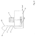
- the level difference between the level container 14 and the filling level in the buffer container 13 is generally 2 to 3 cm. A higher volume flow Q can thus be generated here with the identical level pump 16 at lower speeds. If media are filled that do not have a shear gradient, the overflow arrangement according to FIG. 1 can be dispensed with, since there are no changes in viscosity due to stirring. The associated process regime is to be explained in more detail in FIGS. 2 and 4. 2, the filling pump 23 is arranged directly in the buffer container 21. First, a speed sensor 8 and above that the volume sensors 17, 18 are arranged on the filling pipe 22 in the ascending direction of the volume flow. As shown in Fig. 4, the flow rate sensor 8 measures the increase in the volume flow Q which is caused by the increase in the pump speed.
- the measured flow velocity is compared with the setpoint Wqv and the manipulated variable Uqv formed is output directly to the frequency converter 10 on the filling pump drive 11 '. If the target speed Wqv is reached, the output frequency of the frequency converter 10 is limited and the pump speed is not increased.
- the distances between the flow velocity measuring sensor 8 and the volume sensor 17 are selected so that the stationary flow is reached after a target / actual value comparison and adjustment of the target value and adjustment of the pump speed before the volume sensor 17 is activated. It should be noted that the level in the buffer tank 21 is kept constant by means of a separate level control. This regulates that a necessary filling speed is reached and level fluctuations that would lead to a change in the flow speed Qv are excluded.
- the trailing filling pump 23 generates an increasing filling flow, which is measured by the sensor 8. If the volume sensor 17 is dispensed with and the flow speed measured by the sensor 8 is used to regulate the pump speed, the pump speed is increased until the target / actual value comparison shows that the filling flow is the target speed, which is free of dripping and splashing Filling enables, has achieved. The setpoint reached is stored and held and is no longer changed. The analog measured value of the flow velocity is converted into a pulse sequence proportional to the flow. Speed fluctuations due to small changes in level in the filling container 13 are detected by changing the pulse train and automatically compensated. If the filling medium emerges from the filling head, the sensor 18 is switched. This switching signal is the start signal of the pulse count for volume measurement. After counting the pulse sequence required for the target volume, the filling pump drive 11 is stopped.
Landscapes
- Engineering & Computer Science (AREA)
- Physics & Mathematics (AREA)
- General Physics & Mathematics (AREA)
- Automation & Control Theory (AREA)
- Mechanical Engineering (AREA)
- Basic Packing Technique (AREA)
- Feeding, Discharge, Calcimining, Fusing, And Gas-Generation Devices (AREA)
- Display Devices Of Pinball Game Machines (AREA)
- Rod-Shaped Construction Members (AREA)
- Flow Control (AREA)
- Percussion Or Vibration Massage (AREA)
- Treatment Of Water By Ion Exchange (AREA)
Description
Es ist bekannt, Flüssigkeiten unterschiedlicher Viskosität und Dichte mittels volumengesteuerter Füllautomaten zu dosieren und in Behälter einzufüllen. Die US PS 4 460 026 offenbart eine Flüssigkeitsmessung mit einem Flüssigkeitsabfüllgerät, das mehrere Reservoirelemente in bestimmten Positionen aufweist. Die Reservoirelemente sind aus Rumpf- und Halsteilen gebildet und mit einem Behälterauslaßrohr in Verbindung gebracht. Das Verfahren entsprechend der US PS 4 460 026 weist den Nachteil auf, daß Dosier- und Meßvorgänge in einem separaten Teil der Vorrichtung durchgeführt werden und durch Übermittlungsfehler hohe Meßungenauigkeiten zur Folge haben. Ein weiterer, prägnanter Nachteil förderstromgesteuerter Füllautomaten besteht in einem zeitabhängigen Füllprogramm. Die Zeitabhängigkeit des Füllens, d. h. das Voreinstellen der Füllzeit, unabhängig von der Viskosität und Dichte sowie deren beim Abfüllprozeß auftretenden Veränderungen, führen zu bedeutenden Dosierfehlern, die entweder über eine ständige Nachjustierung der Füllzeit korrigiert werden müssen oder zu einem nachträglichen Auffüllen der Gefäße führen. Ist der Dosier- und Meßvorgang einmal unterbrochen, ist eine nachträgliche Justierung des Zeitprogramms erforderlich, bis die erforderliche Menge eingestellt worden ist. Die DD PS 297 123 offenbart eine Sensoranordnung, bei der die Sensoren am Füllrohr in solchen Abständen angeordnet sind, daß eine Messung des Grundvolumens vorgenommen werden kann. Die Auswertung der Laufzeitdifferenz wird zur Kompensation von Viskositätseinflüssen genutzt. Ein Nachteil der zur Durchführung des Verfahrens gelangenden Anordnung besteht darin, daß die Geschwindigkeit der einzufüllenden Medien, in der Anordnung abhängig von der Viskosität und dem Schergefälle, große Unterschiede aufweisen kann. Bei einer zu großen Geschwindigkeit des Austritts des Füllstrahles aus dem Füllrohr trifft dieser nicht in die Gefäßöffnung, sondern er geht darüber hinaus. Ist die Geschwindigkeit zu gering, klappt der Füllstrahl am Füllrohr ab, und das Medium läuft am Füllrohr bzw. am Behälter herunter. Ein weiterer Nachteil dieser Anordnung besteht darin, daß die für eine gleichmäßige Dosierung notwendige Überlaufanordnung nicht kontinuierlich gefüllt wird und Dosierfehler zur folge hat. Der Anordnung der DD PS 297 123 ist ein weiterer Nachteil eigen, welcher darin zu sehen ist, daß nach Beendigung des Füllvorganges die Pumpenmotore abgeschaltet werden, wodurch das Medium in eine Ruhelage gerät und seine Viskosität verändert. Beim Wiederanlaufen der Pumpenmotoren und bei einem Neubeginn der Dosierung sind umfangreiche Justierarbeiten notwendig, um eine kontinuierliche Dosiergenauigkeit zu erreichen.
- Fig. 1:
- Die Durchführung des Verfahrens mit einen Füllautomaten beim Einfüllen von Medien mit einem Schergefälle
- Fig. 2:
- Die Durchführung des Verfahrens mit einem Füllautomaten beim Einfüllen von Medien ohne Schergefälle
- Fig. 3:
- Eine Darstellung des Verfahrensablaufes gem. Fig. 1
- Fig. 4:
- Eine Darstellung des Verfahrensablaufes gem. Fig. 2
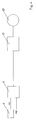
Auf der Druckleitung 19 ist am höchsten Punkt ein Strömungsgeschwindigkeitssensor 1 angeordnet.
Das Auslaßende des aufsteigenden Füllrohres 12 ist so gestaltet, daß der Füllstrahl des abzufüllenden Mediums frei und sicher in die Füllöffnung des zu füllenden Gebindes fließt und ein sauberes und nachtropffreies Abfüllen gewährleistet, wenn das Füllmedium am Austritt eine vorgegebene Sollgeschwindigkeit aufweist.
Diese Sollgeschwindigkeit wird medienabhängig mit unterschiedlichen Drehzahlen der Füllpumpe 15;23, d.h. mit verschiedenen Ausgangsfrequenzen des Frequenzumrichters 10 erreicht. Die Sollgeschwindigkeit für das Befüllen von z.B. 750 ml Dosen mit Latex-Bindemittel wird bei einer Ausgangsfrequenz von ca. 28 Hz erreicht. Für das Befüllen der gleichen Dosengröße mit Latex - Weiß wird, um die benötigte gleiche Sollgeschwindigkeit zu erreichen, eine Ausgangsfrequenz von ca. 38 Hz benötigt. Diese Werte sind noch abhängig davon, ob die Farbe gerade fertig wurde und intensiv gerührt worden ist,und bei welcher Lagertemperatur bzw. wie lange die Farbe bzw. das Abfüllgut gelagert wurde. Dies sind alles Einflußfaktoren, denen zum Erreichen einer vorgegebenen Sollgeschwindigkeit nur durch eine automatische Anpassung der Pumpendrehzahl begegnet werden kann. Andernfalls ist es nötig, vor dem Beginn des Abfüllens die Geschwindigkeit des Füllstrahles manuell einzuregeln. Dieser Einregelvorgang ist zeitaufwendig und Produktverluste durch Bedien- und Eingabefehler sind nicht auszuschließen.
Deshalb wird in Übereinstimmung mit Fig. 3 nach Fig. 1 auf der Druckleitung 19 der Strömungsgeschwindigkeitssensor 1 zur Messung der Strömungsgeschwindigkeit Qv angeordnet. Der Sensor 1 mißt die Strömungsgeschwindigkeit Qv ständig. Der Meßwert Xqv als Ist-Wert der Strömungsgeschwindigkeiten Qv wird in einen Qv-Regler 2 eingelesen und mit einem Soll-Wert Wqv verglichen. Stimmen die Soll- und Ist-Werte überein, erfolgt keine Veränderung in einem Frequenzumrichter 3 und keine Drehzahländerung in Niveaupumpenantrieb 4.
Weichen die Soll- und Ist-Werte voneinander ab, wird ein Spannungssignal Uqv als Stellgröße der Qv-Regelung an den Frequenzumrichter 3 ausgegeben und die Drehzahl des Niveaupumpenantriebes 4 so lange verändert, bis die benötigte Strömungsgeschwindigkeit am Volumensensor 17 eingestellt ist. Dann wird das Spannungsausgangssignal Uqv im Verstärker 5 parametriert, als Stellgröße an den Frequenzumrichter FU 2 ausgegeben und damit beim Füllstart am Füllpumpenantrieb 11 wirksam. Drehzahlveränderungen während einer Füllung werden durch das Regime des Steuerprogrammes nicht zugelassen, gleichfalls können Frequenzveränderungen nur während der Füllpausen vorgenommen werden. Dazu ist das Verfahren in seinen Schritten so eingestellt, daß die Niveaupumpe 16 für ein bestimmtes Füllmedium mit bekannter Viskosität und Dichte, z.B. eine Geschwindigkeit Xqv von 96 cm/s erzeugt. Die Sollwertvorgabe, Geschwindigkeitssollwert Wqv ist 1,5 m/s.
Im Qv-Regler 2 erfolgt nach Fig. 3 ein Spannungsabgleich. Dabei wird ein Spannungswert von z.B. 5 V an den Frequenzumrichter FU 1 ausgegeben und die Ausgangsfrequenz so vergrößert, daß die Drehzahl der Niveaupumpe 16 auf die erforderliche Enddrehzahl von z.B. 900 U/min erhöht wird. Ein gemessener Spanrungswert von z. B. 5 V wird im Verstärker 5 parametriert und an den Frequenzumrichter 6 ausgegeben. Die Verstärkung bzw. Parametrierung ist erforderlich, weil das Füllrohr 12 der Füllpumpe 15 eine Höhe von 30 bis 50 cm bis zum Füllrohrende aufweist. Die Füllpumpe 15 gleicht auch die scheinbare Zunahme der geodätischen Förderhöhe im Füllrohr 12 bei höheren Dichten der Flüssigkeit derart aus, daß immer mit der benötigten Strömungsgeschwindigkeit Qv gefüllt wird. Dieser Ausgleich ist erforderlich, weil bei einer gewählten Pumpenleistung und einem bekannten Füllrohrquerschnitt ein Volumenstrom Q von mindestens 1 l/s erzeugt werden soll. Die Enddrehzahl des Füllpumpenantriebs 11 wird beim beispielsweise gewählten Frequenzumrichter 6 nach ca. 0,1 s erreicht. Der Volumensensor 17 darf erst dann aktiviert werden, wenn die Füllpumpe 15 sicher die erforderliche Drehzahl für die benötigte Sollgeschwindigkeit erreicht hat.
Die Niveaupumpe 16 erzegt für ein bestimmtes Füllmedium mit bekannter Viskosität und Dichte, z. B. eine Geschwindigkeit Xqv Von 96 cm/s. Die Sollwertvorgabe, Geschwindigkeitssollwert Wqv, ist 1,5 m/s.
Im Qv-Regler 2 erfolgt nach Fig. 3 ein Spannungsabgleich, dabei wird ein Spannungswert von z. B. 5 V an den Frequenzumrichter FU 1 ausgegeben und die Ausgangsfrequenz so vergrößert, daß die Drehzahl der Niveaupumpe 16 auf die erforderliche Enddrehzahl von z. B. 900 U/min. erhöht wird. Ein gemessener Spannungswert von z. B. 5 V wird im Verstärker 5 parametriert und an den Frequenzumrichter 6 ausgegeben. Die Verstärkung bzw. Parametrierung ist erforderlich, weil das Füllrohr 12 der Füllpumpe 15 eine Höhe von 30 - 50 cm bis zum Füllrohrende aufweist. Die Füllpumpe 15 gleicht auch die scheinbare Zunahme der geodätischen Förderhöhe im Füllrohr bei höheren Dichten der Flüssigkeit derart aus, daß immer mit der benötigten Strömungsgeschwindigkeit Qv gefüllt wird. Dieser Ausgleich ist erforderlich, weil bei einer gewählten Pumpenleistung und einem vorhandenen Füllrohrquerschnitt ein Volumenstrom Q von mindestens 1 l/s erzeugt wird. Die Enddrehzahl des Füllpumpenantriebs 11 wird beim beispielsweise gewählten Frequenzumrichter 6 nach ca. 0,1 s erreicht. Der Volumensensor 17 darf erst dann aktiviert werden, wenn die Füllpumpe 15 sicher im Bereich der stationären Strömung arbeitet. Deshalb wird der Volumensensor 17 so über dem Füllstand des Niveaubehälters 14 angeordnet, daß mit Sicherheit die Meßstrecke für das gesamte Grundvolumen erst dann zwischen den Volumensensoren 17;18 aktiviert wird, wenn Geschwindigkeitsveränderungen des Volumenstrom Q ausgeschlossen sind.
Die Anordnung nach den Figuren 1 und 3 wird dann gewählt, wenn viskose Füllmedien mit Schergefälle abgefüllt werden. Dispersionen weisen ein ausgeprägtes Schergefälle auf. Als Beispiel soll Latex-Bindemittel genannt werden.
Die Höhendifferenz des Füllgutes im Pufferbehälter 13, zwischen Niveaupumpe 16 und der Überlaufkante des Niveaubehälters 14 im Pufferbehälter 13, ist gering. Der Niveauunterschied zwischen Niveaubehälter 14 und dem Füllgutniveau im Pufferbehälter 13 beträgt im allgemeinen 2 bis 3 cm. Hier kann also mit der baugleichen Niveaupumpe 16 mit geringeren Drehzahlen ein höherer Volumenstrom Q erzeugt werden.
Werden Medien abgefüllt, die kein Schergefälle besitzen, kann auf die Überlaufanordnung nach Fig. 1 verzichtet werden, da hierbei durch Rühren keine Viskositätveränderungen auftreten.
In den Figuren 2 und 4 soll das zugehörige Verfahrensregime näher erläutert werden.
Gemäß Fig. 2 wird die Füllpumpe 23 direkt im Pufferbehälter 21 angeordnet. An Füllrohr 22 sind in aufsteigender Richtung des Volumenstromes zuerst ein Geschwindigkeitssensor 8 und darüber die Volumensensoren 17;18 angeordnet.
Wie in Fig. 4 dargestellt, mißt der Strömungsgeschwindigkeitssensor 8 den Anstieg des Volumenstromes Q, der durch die Erhöhung der Pumppendrehzahl bewirkt wird. Im Qv-Regler 9 wird die gemessene Strömungsgeschwindigkeit mit dem Sollwert Wqv verglichen und die gebildete Stellgröße Uqv wird unmittelbar an den Frequenzumrichter 10 am Füllpumpenantrieb 11' ausgegeben. Ist die Sollgeschwindigkeit Wqv erreicht, erfolgt eine Begrenzung der Ausgangsfrequenz des Frequenzumrichters 10 und damit keine Erhöhung der Pumpendrehzahl. Die Abstände zwischen dem die Strömugsgeschwindigkeit messenden Sensors 8 und dem Volumensensor 17 sind so gewählt, daß die stationäre Strömung nach einem Soll-/Ist-Werte-Vergleich und Einregelung des Sollwertes sowie Verstellung der Pumpendrehzah erreicht ist, bevor der Volumensensor 17 aktiviert wird. Dabei ist zu beachten, daß über eine separate Niveauregelung die Konstanthaltung des Niveaus im Pufferbehälter 21 gewährleistet ist. Damit wird geregelt, daß eine notwendige Füllgeschwindigkeit erreicht wird und Niveauschwankungen, die zu einer Veränderung der Strömungsgeschwindigkeit Qv führen würden, ausgeschlossen sind. Die nachlaufende Füllpumpe 23 erzeugt einen ansteigenden Füllstrom, der vom Sensor 8 gemessen wird. Wird auf den Volumensensor 17 verzichtet und die vom Sensor 8 gemessene Strömungsgeschwindigkeit zur Einregelung der Pumpendrehzahl benutzt, so wird die Pumpendrehzahl so lange erhöht, bis der Soll-Ist-Wert-Vergleich ergibt, daß der Füllstrom die Sollgeschwindigkeit, die ein nachtropf- und spritzfreies Füllen ermöglicht, erreicht hat. Der erreichte Sollwert wird eingespeichert und gehalten und nicht mehr verändert. Der analoge Meßwert der Strömungsgeschwindigkeit wird in eine durchflußproportionale Impulsfolge umgewandelt. Geschwindigkeitsschwankungen durch geringe Niveauänderungen im Füllbehälter 13 werden durch Änderung der Impulsfolge erfaßt und automatisch kompensiert. Tritt das Füllmedium aus dem Füllkopf aus, wird der Sensor 18 geschaltet. Dieses Schaltsignal ist das Startsignal der Impulszählung zur Volumenmessung. Nach der Zählung der für das Sollvolumen erforderlichen Impulsfolge wird der Füllpumpenantrieb 11 gestoppt.
- 1
- Geschwindigkeitssensor
- 2
- Regler Qv
- 3
- Frequenzumrichter
- 4
- Pumpenantrieb
- 5
- Verstärker
- 6
- Frequenzumrichter
- 8
- Geschwindigkeitssensor
- 9
- Regler
- 10
- Frequenzumrichter
- 11;11'
- Füllpumpenantrieb
- 12;22
- Füllrohr
- 13;21
- Pufferbehälter
- 14
- Niveau behälter
- 15;23
- Füllpumpe
- 16
- Niveaupumpe
- 17
- Volumensensor
- 18
- Volumensensor
- 19
- Druckleitung
- 20
- Pumpenläufer
- Q
- Volumenstrom
- Qv
- Strömungsgeschwindigkeit
- Xqv
- Istwert der Strömungsgeschwindigkeit
- Wqv
- Sollwert der Strömungsgeschwindigkeit
- Uqv
- Stellgröße Qv-Regelung (Spannung: 0 ... 10 V)
- FU 1
- Frequenzumrichter Niveaupumpe
- M 1
- Elektroantrieb Niveaupumpe
- FU 2
- Frequenzumrichter Füllpumpe
- M 2
- Elektroantrieb Füllpumpe
Claims (9)
- Verfahren zum Justieren des Füllstrahles förderstromgesteuerter, automatisch arbeitender Füllmaschinen, mit denen Flüssigkeiten unterschiedlicher Viskosität und Dichte dosiert und mit einem frei verlaufenden, gerichteten Füllstrahl in Gefäße gefüllt werden, die Flüssigkeit mittels einer Füllpumpe (15) in ein Füllrohr (12) gepumpt wird, wobei die Flüssigkeit in dem Füllrohr (12) aufsteigend, zwischen darin angeordneten Sensoren zur Bestimmung eines Grundvolumens in Zeitabschnitten gemessen, die Zuführung einer gleichmäßigen Flüssigkeitsmenge für den aufsteigenden Zulauf im Füllrohr (12) durch das Einordnen eines Überlaufes aus einem Niveaubehälter (14) erhalten, und die Zeit zum Ausfüllen des Füllrohres (12), beginnend beim Füllstart in Zeiteinheiten eingeteilt, beim Austritt aus dem Füllrohr (12) beendet wird, wobei die Basis zum Ausfüllen des Volumens des Füllrohres (12) durch die Überlaufanordnung des Niveaubehälters (14), verbunden mit einer stetigen Messung der Viskosität der Flüssigkeit, immer konstant gehalten wird, und aus dem, in einem Pufferbehälter (13) angeordneten Niveaubehälter (14) das Füllrohr (12) ragt, wobei der Niveaubehälter (14) sowie die Füllpumpe (15) einem gemeinsamen Füllmedienbad zugeordnet werden, der Niveaubehälter (14) zum Erzielen eines kontinuierlichen Kreislaufes stetig überfüllt gehalten wird, sowie am aufragenden Ende des Füllrohres (12) eine durch die Sensoren (17;18) gebildete Schranke, über ein Steuersignal mit einer Steuervorrichtung in Verbindung gebracht ist, die über ein Ausgangssignal vor einem Schaltverstärker vorgesehen und verstärkend mit der Füllpumpe verbunden wird, die Steuervorrichtung mit einem Positionssensor (17) über ein Steuersignal in eine Wirkverbindung gebracht wird, und der Niveaubehälter (14) in dem Pufferbehälter (13) angeordnet, die Möglichkeit eröffnet, mit einer Niveaupumpe (16) einen ständigen Kreislauf druckseitig mit dem Niveaubehälter (14) und saugseitig am Pufferbehälter (13) in Verbindung zu erhalten und im Füllrohr (12) in einem bestimmten Abschnitt die zwei Sensoren (17;18) übereinander angeordnet gleichzeitig durch den Abschnitt zwischen den beiden Sensoren (17;18) ein bestimmtes Füllvolumen festgelegt wird, dadurch gekennzeichnet, daß die Geschwindigkeit des aus dem Füllrohr (12) austretenden Füllstrahles als Sollwert festgelegt sowie gespeichert wird und die Ist-Werte der Geschwindigkeit eines aus der Niveaupumpe (16) austretenden Volumenstromes mit einem Geschwindigkeitssensor (1) gemessen und miteinander zur Justierung der Geschwindigkeit des austretenden Füllstrahles einem Vergleich unterzogen werden, wobei die Förderleistung der Niveaupumpe (16) solange verändert wird, bis die Größe des gespeicherten Soll-Wertes der Geschwindigkeit des Füllstrahles am Volumensensor (17;18), mit der am Geschwindigkeitssensor (1) gemessenen Geschwindigkeit des Volumenstromes in Übereinstimmung gebracht worden ist und erst danach der Füllvorgang in die Gefäße eingeleitet wird.
- Verfahren nach Anspruch 1, dadurch gekennzeichnet, daß eine kontinuierliche Messung der Strömungsgeschwindigkeit des aus der Niveaupumpe (16) austretenden Volumenstromes vorgenommen wird, während das Füllmedienbad gefüllt und der Niveaubehälter (14) stetig überfließend gefüllt gehalten wird, wobei die Stetigkeit des Volumenstromes konstant gehalten wird, daß mit einem auf der Druckleitung der Niveaupumpe (16) angeordneten Sensor (1) die vorhandene Geschwindigkeit Qv des Volumenstromes Xqv kontinuierlich gemessen, und mit einem analogen Wert der Sollgeschwindigkeit verglichen wird und als Signal zum Vermindern oder Erhöhen der Drehzahl der Niveaupumpe (16) zur Veränderung der Strömungsgeschwindigkeit von der Steuerung an einen Frequenzumrichter (10) des Niveaupumpenantriebes (4) gegeben wird.
- Verfahren nach Anspruch 1 und 2, dadurch gekennzeichnet, daß das Signal zum Verändern der Drehzahl als analoges Signal dem Frequenzumrichter (10) mitgeteilt wird.
- Verfahren zum Justieren des Füllstrahles förderstromgesteuerter, automatisch arbeitender Füllmaschinen, mit denen Flüssigkeiten unterschiedlicher Viskosität und Dichte dosiert und mit einem frei verlaufenden, gerichteten Füllstrahl in Gefäße gefüllt werden, die Flüssigkeit mittels einer Füllpumpe (23) in ein Füllrohr (22) gepumpt wird, wobei die Basis zum Ausfüllen den Volumens des Füllrohres durch eine Niveauregelung in einem Pufferbehälter (21) immer konstant gehalten wird und die Flüssigkeit in dem Füllrohr (22) aufsteigend, zwischen darin angeordneten Sensoren zur Bestimmung eines Grundvolumens in Zeitabschnitten gemessen, und die Zeit zum Ausfüllen des Füllrohres (22), beginnend beim Füllstart in Zeiteinheiten eingeteilt, beim Austritt aus dem Füllrohr (22) beendet wird, und dazu am aufragenden Ende des Füllrohres (22) eine durch die Sensoren (17;18) gebildete Schranke, über ein Steuersignal mit einer Steuervorrichtung in Verbindung gebracht ist, die über ein Ausgangssignal vor einem Schaltverstärker vorgesehen und verstärkend mit der Füllpumpe (23) verbunden wird, die Steuervorrichtung mit einem Sensor (17) über ein Steuersignal in eine Wirkverbindung gebracht wird, und im Füllrohr (22) in einem bestimmten Abschnitt die zwei Sensoren (17;18) übereinander angeordnet sind, wobei gleichzeitig durch den Abschnitt zwischen den beiden Sensoren (17;18) ein bestimmtes Füllvolumen festgelegt wird, dadurch gekennzeichnet, daß die Niveauregelung im Pufferbehälter (21), sowie die Konstanthaltung des Füllstandes, mittels, eines den Füllstand des Pufferbehälters (21) kontinuierlich abtastenden, berührungslos arbeitenden Geschwindigkeitssensors (8) vorgenommen wird, der die gemessenenen Werte einem Sollwertvergleich zuführt, der bei Feststellung von Wertabweichungen einen Steuerimpuls auslöst, mit dem die Pumpendrehzahl verändert und die Fördermenge sowie -geschwindigkeit dem Sollbedarf angepaßt werden.
- Verfahren nach den Ansprüchen 1 und 2, dadurch gekennzeichnet, daß nach der Feststellung von Wertabweichungen des Volumenstromes ein Steuerimpuls ausgelöst und zur Veränderung des Füllstandes des Behälters (14), ein Ventildurchlaß in seiner Durchlaßfähigkeit verändert wird.
- Verfahren nach Anspruch 4, dadurch gekennzeichnet, daß der Füllstand des Pufferbehälters (21) durch einen am Füllrohr (22) angeordneten Geschwindigkeitssensor (8) gemessen, und die Geschwindigkeitsdifferenz des Volumenstromes zum Füllstand des Behälters (21) in ein Verhältnis gebracht und ausgeglichen wird.
- Verfahren nach Anspruch 1;3 und 5, dadurch gekennzeichnet, daß mit dem als analogen Geschwindigkeitssensor (1) ausgebildeten Sensor nach der Messung der Strömungsgeschwindigkeit Qv des Volumenstromes Q, im zugeordneten analogen Regler, ein Vergleich des gemessenen Wertes der Strömungsgeschwindigkeit Qv mit dem Soll-Wert Wqv vorgenommen wird, wonach die Stellgröße Uqv als Dauersignal ausgegeben und dem Sollwert der Strömungsgeschwindigkeit, für das Halten einer konstanten Drehzahl des Pumpenantriebes (4), angeglichen wird.
- Verfahren nach Anspruch 1;3 und 7, dadurch gekennzeichnet, daß zur Verminderung der Viskosität der Flüssigkeiten mit einem Schergefälle und der Einhaltung ihrer konstanten Viskosität, die Flüssigkeit zwischen dem Pufferbehälter (13) und dem Niveaubehälter (14) in einem angepaßten Zeitabstand vor dem Füllvorgang und in den Füllpausen kontinuierlich umgepumpt wird.
- Verfahren nach Anspruch 4 dadurch gekennzeichnet, daß zur Einhaltung einer konstanten Viskosität, bei Vorliegen eines Endwertes des Schergefälles der Flüssigkeit, der Pumpenantrieb (11) der Füllpumpe (23) des Pufferbehälters (21) aktiviert und ohne zu Pumpen in Bewegung gehalten wird.
Applications Claiming Priority (3)
| Application Number | Priority Date | Filing Date | Title |
|---|---|---|---|
| DE19507831 | 1995-02-22 | ||
| DE19507831 | 1995-02-22 | ||
| PCT/DE1996/000337 WO1996026110A1 (de) | 1995-02-22 | 1996-02-20 | Verfahren zum justieren eines füllstrahles |
Publications (2)
| Publication Number | Publication Date |
|---|---|
| EP0756559A1 EP0756559A1 (de) | 1997-02-05 |
| EP0756559B1 true EP0756559B1 (de) | 1998-12-09 |
Family
ID=7755791
Family Applications (1)
| Application Number | Title | Priority Date | Filing Date |
|---|---|---|---|
| EP96904713A Expired - Lifetime EP0756559B1 (de) | 1995-02-22 | 1996-02-20 | Verfahren zum justieren eines füllstrahles |
Country Status (8)
| Country | Link |
|---|---|
| US (1) | US5794668A (de) |
| EP (1) | EP0756559B1 (de) |
| JP (1) | JPH10503999A (de) |
| AT (1) | ATE174279T1 (de) |
| AU (1) | AU697630B2 (de) |
| CA (1) | CA2188532A1 (de) |
| DE (2) | DE19608355A1 (de) |
| WO (1) | WO1996026110A1 (de) |
Cited By (1)
| Publication number | Priority date | Publication date | Assignee | Title |
|---|---|---|---|---|
| DE102005033292A1 (de) * | 2005-07-16 | 2007-01-25 | I.N.T.-Rickert Gmbh | Vorrichtung zum Auftragen von Kleb- oder Dichtstoffen |
Families Citing this family (3)
| Publication number | Priority date | Publication date | Assignee | Title |
|---|---|---|---|---|
| DE102008049937A1 (de) | 2008-10-02 | 2010-04-29 | Khs Ag | Vorrichtung sowie Verfahren zum Behandeln von Behältern |
| CN111251491B (zh) * | 2018-12-03 | 2022-02-22 | 宁波优禾新材料科技有限公司 | 用于色母粒生产的设备 |
| CN121292352B (zh) * | 2025-12-12 | 2026-03-17 | 苏州文通智能设备有限公司 | 一种多合一旋转式酱料灌装系统 |
Family Cites Families (5)
| Publication number | Priority date | Publication date | Assignee | Title |
|---|---|---|---|---|
| US4460026A (en) * | 1982-02-16 | 1984-07-17 | Hurley Byron H | Liquid filling apparatus and method |
| US5012955A (en) * | 1989-10-30 | 1991-05-07 | Abc/Sebrn Techcorp. | Syrup dispensing system |
| DE4006186C2 (de) * | 1990-02-28 | 1996-09-26 | Ewald Hennel | Verfahren zur Regelung der Drehzahl einer von einem drehzahlgeregelten Elektromotor angetriebenen Pumpe |
| DD297123B5 (de) * | 1990-08-07 | 1994-08-11 | Wolfgang Dipl-Ing Schroeder | Verfahren und Einrichtung zum dosierten Einfuellen fliessfaehiger Medien in Gefaesse |
| US5316444A (en) * | 1993-04-29 | 1994-05-31 | Wicnienski Michael F | Pump control and method of pumping |
-
1996
- 1996-02-20 EP EP96904713A patent/EP0756559B1/de not_active Expired - Lifetime
- 1996-02-20 AT AT96904713T patent/ATE174279T1/de not_active IP Right Cessation
- 1996-02-20 US US08/732,415 patent/US5794668A/en not_active Expired - Fee Related
- 1996-02-20 DE DE19608355A patent/DE19608355A1/de not_active Withdrawn
- 1996-02-20 AU AU64613/96A patent/AU697630B2/en not_active Ceased
- 1996-02-20 DE DE59600945T patent/DE59600945D1/de not_active Expired - Fee Related
- 1996-02-20 CA CA002188532A patent/CA2188532A1/en not_active Abandoned
- 1996-02-20 WO PCT/DE1996/000337 patent/WO1996026110A1/de not_active Ceased
- 1996-02-20 JP JP8525307A patent/JPH10503999A/ja active Pending
Cited By (2)
| Publication number | Priority date | Publication date | Assignee | Title |
|---|---|---|---|---|
| DE102005033292A1 (de) * | 2005-07-16 | 2007-01-25 | I.N.T.-Rickert Gmbh | Vorrichtung zum Auftragen von Kleb- oder Dichtstoffen |
| DE102005033292B4 (de) * | 2005-07-16 | 2007-07-26 | I.N.T.-Rickert GmbH Ingenieurbüro für neue Technologien | Vorrichtung zum Auftragen von Kleb- oder Dichtstoffen |
Also Published As
| Publication number | Publication date |
|---|---|
| DE59600945D1 (de) | 1999-01-21 |
| WO1996026110A1 (de) | 1996-08-29 |
| CA2188532A1 (en) | 1996-08-29 |
| DE19608355A1 (de) | 1996-08-29 |
| ATE174279T1 (de) | 1998-12-15 |
| US5794668A (en) | 1998-08-18 |
| EP0756559A1 (de) | 1997-02-05 |
| AU6461396A (en) | 1996-09-11 |
| JPH10503999A (ja) | 1998-04-14 |
| AU697630B2 (en) | 1998-10-15 |
Similar Documents
| Publication | Publication Date | Title |
|---|---|---|
| DE69201928T2 (de) | Verfahren zur gewichtsmässigen Dosierung beim Füllen von Behältern. | |
| DE60017373T2 (de) | Präzisions-abgabevorrichtung für flüssigkeiten | |
| DE102011122268B3 (de) | Verfahren und Vorrichtung zum Dosieren eines fluiden Mediums | |
| EP0334213A2 (de) | Verfahren zur kontinuierlichen Herstellung eines fliessfähigen Gemisches | |
| DE3942496A1 (de) | Verfahren zum dosierten auftragen eines fluessigen bindemittels, insbesondere von bitumen, auf eine oberflaeche | |
| EP0756559B1 (de) | Verfahren zum justieren eines füllstrahles | |
| DE69724431T2 (de) | Befüllvorrichtung | |
| EP0756558B1 (de) | Verfahren und einrichtung zum dosieren fliessfähiger medien | |
| DE4041727C2 (de) | ||
| DE2922483A1 (de) | Verfahren und vorrichtung zur volumetrischen messung von fluessigkeiten | |
| EP2801462B1 (de) | Verfahren und Vorrichtung zur gesteuerten Entnahme von flüssigen Materialien aus mehreren Vorlagebehältern | |
| EP1884466B1 (de) | Abfüll-Anlage für fliessfähige Massen | |
| WO1992002787A1 (de) | Verfahren und einrichtung zum volumendosierten einfüllen fliessfähiger medien in gefässe | |
| DE1907906B2 (de) | Verfahren zum Aufrechterhalten eines gleichen und dauernden Flüssigkeitsstromes zu und von einem mit Unterbrechung arbeitenden Gerät und eine Vorrichtung zum Durchführen dieses Verfahrens | |
| EP0482151B1 (de) | Flüssigkeits-auftragsanlage | |
| DE1720113B2 (de) | Vorrichtung zur selbsttätigen Herstellung einer Mischung verschiedener Flüssigkeiten | |
| DE19519432C2 (de) | Verfahren und Vorrichtung zum Versprühen einer Flüssigkeit | |
| DE730397C (de) | Verfahren zur Herstellung eines stroemenden Fluessigkeitsgemisches, welches zwei oder mehrere Fluessigkeiten in konstantem Mengenverhaeltnis enthaelt | |
| DE102020112076B4 (de) | Pegelhaltung | |
| DE102010004068B4 (de) | Verfahren und Befüllvorrichtung zum Befüllen einer Kartusche mit zumindest einem Material | |
| EP0179189A2 (de) | Verfahren und Vorrichtung zur Dosierung und Mischung zweier Fluidkomponenten | |
| DE19725908C2 (de) | Verfahren und Vorrichtung zum Dosieren fließfähgiger Medien | |
| DE4130413C2 (de) | Anlage zum Mischen und/oder Homogenisieren flüssiger Komponenten | |
| DE1186644B (de) | Einrichtung zum selbsttaetigen Regeln des Mischungsverhaeltnisses mehrerer Fluessigkeitsmengen | |
| DE102023116960A1 (de) | Verfahren zum Betreiben eines Betonpumpensystems, Betonpumpensystem, Computerprogrammprodukt |
Legal Events
| Date | Code | Title | Description |
|---|---|---|---|
| PUAI | Public reference made under article 153(3) epc to a published international application that has entered the european phase |
Free format text: ORIGINAL CODE: 0009012 |
|
| AK | Designated contracting states |
Kind code of ref document: A1 Designated state(s): AT BE CH DE FR GB IT LI SE |
|
| 17P | Request for examination filed |
Effective date: 19970227 |
|
| 17Q | First examination report despatched |
Effective date: 19970527 |
|
| GRAG | Despatch of communication of intention to grant |
Free format text: ORIGINAL CODE: EPIDOS AGRA |
|
| GRAG | Despatch of communication of intention to grant |
Free format text: ORIGINAL CODE: EPIDOS AGRA |
|
| GRAG | Despatch of communication of intention to grant |
Free format text: ORIGINAL CODE: EPIDOS AGRA |
|
| GRAH | Despatch of communication of intention to grant a patent |
Free format text: ORIGINAL CODE: EPIDOS IGRA |
|
| GRAH | Despatch of communication of intention to grant a patent |
Free format text: ORIGINAL CODE: EPIDOS IGRA |
|
| GRAA | (expected) grant |
Free format text: ORIGINAL CODE: 0009210 |
|
| AK | Designated contracting states |
Kind code of ref document: B1 Designated state(s): AT BE CH DE FR GB IT LI SE |
|
| PG25 | Lapsed in a contracting state [announced via postgrant information from national office to epo] |
Ref country code: IT Free format text: LAPSE BECAUSE OF FAILURE TO SUBMIT A TRANSLATION OF THE DESCRIPTION OR TO PAY THE FEE WITHIN THE PRESCRIBED TIME-LIMIT;WARNING: LAPSES OF ITALIAN PATENTS WITH EFFECTIVE DATE BEFORE 2007 MAY HAVE OCCURRED AT ANY TIME BEFORE 2007. THE CORRECT EFFECTIVE DATE MAY BE DIFFERENT FROM THE ONE RECORDED. Effective date: 19981209 Ref country code: GB Free format text: LAPSE BECAUSE OF NON-PAYMENT OF DUE FEES Effective date: 19981209 Ref country code: FR Free format text: LAPSE BECAUSE OF FAILURE TO SUBMIT A TRANSLATION OF THE DESCRIPTION OR TO PAY THE FEE WITHIN THE PRESCRIBED TIME-LIMIT Effective date: 19981209 |
|
| REF | Corresponds to: |
Ref document number: 174279 Country of ref document: AT Date of ref document: 19981215 Kind code of ref document: T |
|
| REG | Reference to a national code |
Ref country code: CH Ref legal event code: EP |
|
| REF | Corresponds to: |
Ref document number: 59600945 Country of ref document: DE Date of ref document: 19990121 |
|
| PG25 | Lapsed in a contracting state [announced via postgrant information from national office to epo] |
Ref country code: AT Free format text: LAPSE BECAUSE OF NON-PAYMENT OF DUE FEES Effective date: 19990220 |
|
| PG25 | Lapsed in a contracting state [announced via postgrant information from national office to epo] |
Ref country code: BE Free format text: LAPSE BECAUSE OF NON-PAYMENT OF DUE FEES Effective date: 19990228 |
|
| PG25 | Lapsed in a contracting state [announced via postgrant information from national office to epo] |
Ref country code: SE Free format text: LAPSE BECAUSE OF FAILURE TO SUBMIT A TRANSLATION OF THE DESCRIPTION OR TO PAY THE FEE WITHIN THE PRESCRIBED TIME-LIMIT Effective date: 19990309 |
|
| EN | Fr: translation not filed | ||
| GBV | Gb: ep patent (uk) treated as always having been void in accordance with gb section 77(7)/1977 [no translation filed] |
Effective date: 19981209 |
|
| BERE | Be: lapsed |
Owner name: AFUEMA ABFULLMASCHINEN G.M.B.H. Effective date: 19990228 |
|
| PLBE | No opposition filed within time limit |
Free format text: ORIGINAL CODE: 0009261 |
|
| STAA | Information on the status of an ep patent application or granted ep patent |
Free format text: STATUS: NO OPPOSITION FILED WITHIN TIME LIMIT |
|
| 26N | No opposition filed | ||
| PG25 | Lapsed in a contracting state [announced via postgrant information from national office to epo] |
Ref country code: LI Free format text: LAPSE BECAUSE OF NON-PAYMENT OF DUE FEES Effective date: 20000229 Ref country code: CH Free format text: LAPSE BECAUSE OF NON-PAYMENT OF DUE FEES Effective date: 20000229 |
|
| REG | Reference to a national code |
Ref country code: CH Ref legal event code: PL |
|
| PGFP | Annual fee paid to national office [announced via postgrant information from national office to epo] |
Ref country code: DE Payment date: 20010427 Year of fee payment: 6 |
|
| PG25 | Lapsed in a contracting state [announced via postgrant information from national office to epo] |
Ref country code: DE Free format text: LAPSE BECAUSE OF NON-PAYMENT OF DUE FEES Effective date: 20020903 |