EP0756347A2 - Brennstoffzelle mit Elektrolyten aus festem Oxid - Google Patents
Brennstoffzelle mit Elektrolyten aus festem Oxid Download PDFInfo
- Publication number
- EP0756347A2 EP0756347A2 EP96112130A EP96112130A EP0756347A2 EP 0756347 A2 EP0756347 A2 EP 0756347A2 EP 96112130 A EP96112130 A EP 96112130A EP 96112130 A EP96112130 A EP 96112130A EP 0756347 A2 EP0756347 A2 EP 0756347A2
- Authority
- EP
- European Patent Office
- Prior art keywords
- gas
- cell
- substrate
- passage
- passages
- Prior art date
- Legal status (The legal status is an assumption and is not a legal conclusion. Google has not performed a legal analysis and makes no representation as to the accuracy of the status listed.)
- Granted
Links
Images


Classifications
-
- H—ELECTRICITY
- H01—ELECTRIC ELEMENTS
- H01M—PROCESSES OR MEANS, e.g. BATTERIES, FOR THE DIRECT CONVERSION OF CHEMICAL ENERGY INTO ELECTRICAL ENERGY
- H01M8/00—Fuel cells; Manufacture thereof
- H01M8/24—Grouping of fuel cells, e.g. stacking of fuel cells
- H01M8/241—Grouping of fuel cells, e.g. stacking of fuel cells with solid or matrix-supported electrolytes
- H01M8/2425—High-temperature cells with solid electrolytes
-
- H—ELECTRICITY
- H01—ELECTRIC ELEMENTS
- H01M—PROCESSES OR MEANS, e.g. BATTERIES, FOR THE DIRECT CONVERSION OF CHEMICAL ENERGY INTO ELECTRICAL ENERGY
- H01M8/00—Fuel cells; Manufacture thereof
- H01M8/02—Details
- H01M8/0202—Collectors; Separators, e.g. bipolar separators; Interconnectors
- H01M8/0258—Collectors; Separators, e.g. bipolar separators; Interconnectors characterised by the configuration of channels, e.g. by the flow field of the reactant or coolant
- H01M8/0263—Collectors; Separators, e.g. bipolar separators; Interconnectors characterised by the configuration of channels, e.g. by the flow field of the reactant or coolant having meandering or serpentine paths
-
- H—ELECTRICITY
- H01—ELECTRIC ELEMENTS
- H01M—PROCESSES OR MEANS, e.g. BATTERIES, FOR THE DIRECT CONVERSION OF CHEMICAL ENERGY INTO ELECTRICAL ENERGY
- H01M8/00—Fuel cells; Manufacture thereof
- H01M8/02—Details
- H01M8/0202—Collectors; Separators, e.g. bipolar separators; Interconnectors
- H01M8/0258—Collectors; Separators, e.g. bipolar separators; Interconnectors characterised by the configuration of channels, e.g. by the flow field of the reactant or coolant
- H01M8/0265—Collectors; Separators, e.g. bipolar separators; Interconnectors characterised by the configuration of channels, e.g. by the flow field of the reactant or coolant the reactant or coolant channels having varying cross sections
-
- H—ELECTRICITY
- H01—ELECTRIC ELEMENTS
- H01M—PROCESSES OR MEANS, e.g. BATTERIES, FOR THE DIRECT CONVERSION OF CHEMICAL ENERGY INTO ELECTRICAL ENERGY
- H01M8/00—Fuel cells; Manufacture thereof
- H01M8/10—Fuel cells with solid electrolytes
- H01M8/12—Fuel cells with solid electrolytes operating at high temperature, e.g. with stabilised ZrO2 electrolyte
- H01M8/1231—Fuel cells with solid electrolytes operating at high temperature, e.g. with stabilised ZrO2 electrolyte with both reactants being gaseous or vaporised
-
- H—ELECTRICITY
- H01—ELECTRIC ELEMENTS
- H01M—PROCESSES OR MEANS, e.g. BATTERIES, FOR THE DIRECT CONVERSION OF CHEMICAL ENERGY INTO ELECTRICAL ENERGY
- H01M8/00—Fuel cells; Manufacture thereof
- H01M8/24—Grouping of fuel cells, e.g. stacking of fuel cells
- H01M8/2404—Processes or apparatus for grouping fuel cells
-
- H—ELECTRICITY
- H01—ELECTRIC ELEMENTS
- H01M—PROCESSES OR MEANS, e.g. BATTERIES, FOR THE DIRECT CONVERSION OF CHEMICAL ENERGY INTO ELECTRICAL ENERGY
- H01M8/00—Fuel cells; Manufacture thereof
- H01M8/24—Grouping of fuel cells, e.g. stacking of fuel cells
- H01M8/241—Grouping of fuel cells, e.g. stacking of fuel cells with solid or matrix-supported electrolytes
- H01M8/2425—High-temperature cells with solid electrolytes
- H01M8/2432—Grouping of unit cells of planar configuration
-
- H—ELECTRICITY
- H01—ELECTRIC ELEMENTS
- H01M—PROCESSES OR MEANS, e.g. BATTERIES, FOR THE DIRECT CONVERSION OF CHEMICAL ENERGY INTO ELECTRICAL ENERGY
- H01M8/00—Fuel cells; Manufacture thereof
- H01M8/24—Grouping of fuel cells, e.g. stacking of fuel cells
- H01M8/2457—Grouping of fuel cells, e.g. stacking of fuel cells with both reactants being gaseous or vaporised
-
- H—ELECTRICITY
- H01—ELECTRIC ELEMENTS
- H01M—PROCESSES OR MEANS, e.g. BATTERIES, FOR THE DIRECT CONVERSION OF CHEMICAL ENERGY INTO ELECTRICAL ENERGY
- H01M8/00—Fuel cells; Manufacture thereof
- H01M8/10—Fuel cells with solid electrolytes
- H01M8/12—Fuel cells with solid electrolytes operating at high temperature, e.g. with stabilised ZrO2 electrolyte
- H01M2008/1293—Fuel cells with solid oxide electrolytes
-
- H—ELECTRICITY
- H01—ELECTRIC ELEMENTS
- H01M—PROCESSES OR MEANS, e.g. BATTERIES, FOR THE DIRECT CONVERSION OF CHEMICAL ENERGY INTO ELECTRICAL ENERGY
- H01M2300/00—Electrolytes
- H01M2300/0017—Non-aqueous electrolytes
- H01M2300/0065—Solid electrolytes
- H01M2300/0068—Solid electrolytes inorganic
- H01M2300/0071—Oxides
- H01M2300/0074—Ion conductive at high temperature
-
- Y—GENERAL TAGGING OF NEW TECHNOLOGICAL DEVELOPMENTS; GENERAL TAGGING OF CROSS-SECTIONAL TECHNOLOGIES SPANNING OVER SEVERAL SECTIONS OF THE IPC; TECHNICAL SUBJECTS COVERED BY FORMER USPC CROSS-REFERENCE ART COLLECTIONS [XRACs] AND DIGESTS
- Y02—TECHNOLOGIES OR APPLICATIONS FOR MITIGATION OR ADAPTATION AGAINST CLIMATE CHANGE
- Y02E—REDUCTION OF GREENHOUSE GAS [GHG] EMISSIONS, RELATED TO ENERGY GENERATION, TRANSMISSION OR DISTRIBUTION
- Y02E60/00—Enabling technologies; Technologies with a potential or indirect contribution to GHG emissions mitigation
- Y02E60/30—Hydrogen technology
- Y02E60/50—Fuel cells
Definitions
- This invention relates to the structure of a power generation cell of a solid oxide fuel cell.
- a solid oxide fuel cell (hereinafter referred to as "SOFC") basically has a structure which is consisted of an electrolyte having selective permeability of oxide ion, an air electrode and a fuel electrode.
- the electrolyte is disposed between the air electrode and the fuel electrode, and the individual electrodes are supplied with a gas containing oxygen or hydrogen to generate a power.
- the solid oxide electrolyte is required to be a dense sintered body which is required to be superior in permeability of only oxide ion but have no permeability of the gas.
- YSZ yttria-stabilized zirconia
- the fuel electrode uses a cermet of nickel (or nickel oxide) with YSZ
- the air electrode uses LaSrMnO 3 based substance as an electrically-conductive composite oxide having a perovskite type structure.
- Conductivities of the three components are approximately 1000, 100, and 0.1 (S/cm), respectively, in the decreasing order of the fuel electrode, the air electrode, and the electrolyte.
- the electrolyte is particularly small in conductivity, it is basically desired that the electrolyte is formed to a thin film as possible in view of the improvement of the power generation characteristics.
- the production method of the single cell and connection of a plurality of cells should be sufficiently taken into consideration. As a result, presently, a variety of structures are selected in the cell production.
- Fig. 7A and Fig. 7B show examples of cell structures of conventional SOFC produced in the past.
- Fig. 7A shows a flat plate type cell 77 in which an electrolyte 71 is sandwiched between a fuel electrode 72 and an air electrode 73.
- the electrolyte 71 has a thickness of 300 - 500 ⁇ m
- the electrodes 72 and 73 have thicknesses of up to 100 ⁇ m
- the entire cell has a thickness of about 500 - 700 ⁇ m.
- the numeral 74 indicates an interconnector
- 75 is a fuel gas passage
- 76 is an oxidant gas passage.
- FIG. 7B shows a partially enlarged figure of an example of a tubular type cell using the method.
- This cell 77 has a structure in which the air electrode 73, the electrolyte 71, and the fuel electrode 72 are wound round in this order on the outer periphery of a support tube 78 having a hollow part as the oxidant gas passage 76.
- the fuel gas passage 75 is disposed on the periphery of the cell 77.
- the numeral 74 indicates the interconnector.
- the electrolyte can be formed substantially thin, which, as described above, meets the requirement of SOFC cell that the electrolyte film be formed thin. Further, since the cell is supported by the support tube, it has a high strength and stacking is easy. However, in this cell, as a problem inherent to the shape of the cell, since current during power generation flows along the electrode layer, there is a large voltage drop in this portion, and high power generation characteristics are not achieved.
- a method which uses a hollow flat plate-formed porous electrode as a cell substrate.
- Fig. 7C shows a cell of this type (Japanese Patent Application Laid-open No. 168729/1994).
- the cell substrate comprises the porous electrode having a conductivity, the current during power generation can be flowed perpendicular to the cell, and power generation characteristics better than the tubular type can be expected.
- the cell of Fig. 7B Japanese Patent Application Laid-open No. 168729/1994.
- the gas flow passage provided in the electrode as the substrate is formed in two stages, gas supplied to the passage of one stage is preheated as it passes through there, after being turned back at the innermost of the substrate, and reaches the gas passage immediately beneath the power generation portion, where a reaction takes place.
- gas supplied to the passage of one stage is preheated as it passes through there, after being turned back at the innermost of the substrate, and reaches the gas passage immediately beneath the power generation portion, where a reaction takes place.
- a longer dwell time in the supply passage is advantageous to achieve sufficient preheating.
- the supply passage and the discharge passage have the same cross-sectional forms, flow rates of the individual supplied gas are the same in the individual passages.
- gas preheat is insufficient only in the supply passage, and preheat is continued after passing through the return back portion and after reaching the discharge passage, where the power generation reaction should be made.
- a predetermined temperature is attained in the discharge passage, decreasing the surface area of the power generation portion effectively acting upon the power generation reaction, resulting in a reduced amount of power generation reaction as a whole.
- the present invention relates to a self supporting film type SOFC which uses a hollow flat plate type substrate as a cell substrate comprising the electrode material and having therein a gas flow passage, discloses details of the structure of the single cell and the stack.
- a primary object of the present invention is to improve thin film formation of the electrolyte and gas sealability and easily achieve a high performance SOFC.
- the present invention provides a solid oxide fuel cell comprising an electrode, a solid electrolyte, and an interconnector, wherein a single cell comprises the electrolyte formed on a first main surface of a cell substrate formed of a first electrode material, a second electrode is formed on top of the electrolyte, and the interconnector is formed on a second main surface differing from the surface formed with the electrolyte, the cell substrate is porous, flat-formed, and has therein a plurality of flow passages of the gas corresponding to the first electrode material, the flow passage of the gas is formed in multiple stages in the substrate, forming a plurality of gas flow passages as supply passages and a plurality of gas flow passages as return passages, these supply passages and return passages communicate with each other at a gas turn back portion in the substrate, and openings of the supply passage and the return passage are located on a side surface of the substrate.
- the gas flow passage provided in the cell substrate may have a structure so that the flow rate in the supply passage of the gas supplied to the cell substrate is slower than the flow rate of the gas in the return passage.
- a total cross sectional area of the gas supply passage provided in the cell substrate may be larger than a total cross sectional area of the return passage.
- the number of stages of the gas flow passage used for the supply passage may be more than that of the return passage.
- Small holes communicating the individual flow passages may be provided in a partition wall between the gas flow passages of the supply passage and the return passage.
- Each single cell may be mounted in the state of face contact in series through a material having a gas permeability and a conductivity and, in this state, encased in a shell having a gas supply chamber for supplying gas to the supply passage in the cell substrate, a discharge chamber of the gas returned from the return passage, and a power generation chamber supplied with the gas corresponding to the second electrode, of the gas flow passages, the supply passage may be opened to the gas supply chamber, the return passage may be opened to the gas discharge chamber, and the single cell unit may be disposed in the power generation chamber supplied with the gas corresponding to the second electrode.
- (La 1-x Sr x )yMnO 3 may be used as the first electrode material constituting the cell substrate, nickel zirconia cermet as the second electrode material, and a zirconium oxide doped with yttrium oxide as the electrolyte.
- a major feature of the present invention is that a hollow flat plate type substrate in which a plurality of passages used for supply and discharge of a gas being formed of the electrode materials are disposed in multi-stages, and on the surface of which are formed layers of the electrolyte and other electrodes.
- a type in which a tubular pipe comprising an inactive substance is used as a support tube, and electrolyte and electrodes are formed on the surface and a type in which three layers are formed in a flat form as a flat plate type cell.
- a cell substrate in which a plurality of gas supply and return passages are provided in stages in the substrate as in the present invention, and openings thereof are disposed on one side.
- the gas supply port and discharge port to the substrate are disposed on the same side surface. As a result, when a stack is formed, this substrate is mounted, only the side where the openings are present is gas sealed, and the gases flowed in and outside the substrate can be separated.
- this substrate is mounted, only the side where the openings are present is gas sealed, and the gases flowed in and outside the substrate can be separated.
- multi-stage gas passage provided in a hollow flat porous electrode are used for gas supply and discharge, in this case, since the gas flow rate in the supply passage is reduced compared to the return passage, when the sectional shapes of the supply and return passages are the same, a more number of stages are used for the supply passage than for the return passage, or when the number of stages of the supply passage is equal to that of return passage, the sectional area of the supply passage is made larger than that of the return passage. This allows sufficient preheat of the gas in the supply passage and, after passing through the turn back portion and when the return passage is reached, supply of sufficiently preheated gas.
- some of the gas can be diffused in the substrate as porous sintered body and supplied into the return passage to generate a power, thereby achieving uniform power generation reaction of the entire substrate in conjunction with the power generation reaction occurring after the turn back portion of the return passage.
- FIG. 1A, Fig. 1B, Fig. 1C, and Fig. 1D show an embodiment of the structure of a single cell of the solid oxide fuel cell according to the present invention, of which Fig. 1A is a perspective view, Fig. 1B is an A-A' cross sectional view, Fig. 1C is a B-B' cross sectional view, and Fig. 1D is a C-C' cross sectional view.
- a single cell 5 of the present invention comprises a power generation portion in which individual layers of a solid oxide electrolyte 2 and a second electrode 3 are formed on one surface of an electrode substrate 1 of such a structure, and an interconnector 4 is provided on the opposite side to the surface on which the power generation portion is formed.
- the substrate air electrode
- the second electrode is based on a nickel zirconia cermet
- the electrolyte is based on YSZ.
- the interconnector 4 is made of a LaCrO 3 based substance which is stable under an oxidation-reduction environment.
- the numeral 6 indicates a gas supply passage
- 7 is a gas return passage
- 8 is a gas turn back portion in the substrate
- 9 is a support for supporting the upper and lower parts of the substrate.
- Fig. 2A, Fig. 2B and Fig. 3 show other embodiments of a single cell of the solid oxide fuel cell according to the present invention.
- inlets of the gas supply passage 6 and gas discharge passage 7 into the substrate are narrowed in order to enhance the gas separation effect at the supply port of the gas supply passage 6 into the substrate and the discharge port of the gas discharge passage 7.
- the gas passages 6 and 7 are formed in three stages and, in this example, the lower two stages are used as the supply passage (gas supply passage 6), and the upper stage is used as the return passage (gas discharge passage 7).
- selection of the number of these passages is flexible and, considering a gas preheating effect, the number of supply passage and the return passage can be appropriately selected.
- the single cell 5 is formed in this structure to ensure the cell strength. Therefore, the electrolyte may be as thin as several to several tens of ⁇ m, thereby substantially reducing the resistance of the electrolyte which is largely concerned with the cell performance.
- the substrate is formed of an electrode material of high conductivity, is not simply hollow shaped, but is provided therein with a support. Therefore, since the current flows through the support of the substrate, the resistance can be prevented from increasing. As a result, even if the thickness of the hollow substrate is increased to about 1 cm, a decrease in resistance due to the thin film formation of the electrolyte is greater than an increase in resistance of the substrate due to the increase in the thickness, which is not a problem in view of the entire cell.
- the gas supplied to the individual electrodes are perfectly separated between the inside and outside of the electrode substrate. Cross leak of the individual gases can be positively prevented by providing a seal on one side of the cell.
- the gas flow passages in the substrate are formed in multiple stages, the individual passages are supply and return passages, and since these passages communicate with each other at the innermost of the substrate, after the gas reaches the innermost of the substrate, it is turned back to be supplied to the reaction section, and the gas can be preheated during this period.
- the gas supply port and the discharge port are located on the same side surface, but are not positioned on the same straight line. Therefore, separation of the individual gas can be effectively achieved by sealing the side surface where the gas supply port and the gas discharge port exist.
- the electrolyte which is to be formed to a thin film cannot be formed thin in order to ensure the cell strength, which is a main cause of resistance of the entire cell. Further, sealing is required on the four sides around the cell.
- the present invention has not such a problem.
- the electrolyte can be formed to a thin film in the prior art tubular type cell, the power generation current flows in the horizontal direction in the electrode layer, which results in an increase in resistance.
- the current is flowed in the direction vertical to the substrate by using a hollow flat substrate, thereby preventing a specific current flow occurring in the tubular type with no degradation of the power generation characteristics.
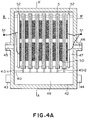
- FIG. 4A, Fig. 4B, Fig. 4C, Fig. 4D, and Fig. 4E show combination examples of the power generation module in the present invention.
- a module using the single cells as shown in Fig. 2A and Fig. 2B will be described.
- the numeral 40 indicates a cell holding plate
- 40-1 is a gas supply slit
- 40-2 is a gas discharge slit
- 41 is a cell supporting plate
- 42 is a shell
- 43 is an oxidant gas supply port
- 44 is an oxidant gas discharge port
- 45 is a fuel gas supply port
- 46 is a fuel gas discharge port
- 47 is a power generation chamber
- 48 is an oxidant gas supply chamber
- 49 is an oxidant gas discharge chamber
- 50 is a conductive spacer
- 51 is a conductor
- 52 is a seal.
- the fuel gas supply port 45 and the fuel gas discharge port 46 or the oxidant gas supply port 43, the oxidant gas discharge port 44 are shown on the right and left side surfaces of the shell 42, they are located on the front (or backside) surface of the paper in view of improvement of contact of the gas with the fuel electrode or the gas with the air electrode.
- the single cell 5 is positioned by the cell supporting plate 41 and the cell holding plate 40 and, in this state, encased in the shell 42.
- the cell holding plate 40 for holding the single cell 5 is provided with the gas supply slit 40-1 and the gas discharge slit 40-2, whereby making gas supply to the substrate and discharge of gas unused in the reaction.
- the fuel gas is supplied from the fuel gas supply port 45 to the power generation chamber 47, and unreacted fuel and water vapor as a reaction product are discharged from the fuel gas discharge port 46 to the outside.
- conductive spacers 50 comprising a material which is superior in gas permeability such as nickel felt are disposed between the single cells, and the individual cells are assembled in a face contact state. Therefore, the individual cells are electrically connected in series, and the fuel gas can be efficiently supplied to the power generation section without hindering diffusion of the gas between the individual cells to generate a power.
- the power generation module is installed under the temperature condition of 900 to 1000°C, and each gas is supplied.
- the oxidant gas is supplied from the oxidant gas supply port 43, reaches and passes inside of each single cell 5 through the gas supply slit 40-1, preheated during this time, after passing through the turn back portion, and reaches the cell formation section, where the reaction takes place, and then the residual gas reaches the oxidant gas discharge chamber 49. Therefore, of the gas passages provided in the substrate, the portion before the turn back portion acts as a gas preheating portion.
- the fuel gas is supplied from the fuel gas supply port 45 provided on the side surface of the shell 42 to the inside of the power generation chamber 47, where power generation is carried out.
- the supplied fuel gas flows into gaps of the porous conductive spacers 50 disposed between the individual cells where it reacts, diffusion of the fuel gas to the electrode is carried out without disturbance.
- the fuel gas which is not consumed by the reaction in this portion is discharged from the fuel gas discharge port 46 to the outside of the shell 42.
- a major advantage of the module using the single cell of the above-described structure is that the supplied gas can be preheated within the substrate. That is, since the gas passage is formed in stages in the substrate, in the supply passage no reaction takes place until reaching the innermost portion of the substrate, and after passing through the turn back portion the entire surface is supplied with the gas to start the reaction. Therefore, as in gas supply method of the prior art flat plate type cell, since gas supply to the entire surface of the cell is made simultaneously, the power generation reaction in the cell can be uniformized. Further, the gas before being used for power generation is preheated when it flows in the substrate, since the gas absorbs heat at this time, thereby preventing local heating in the substrate and positively contributing to the uniform temperature distribution in the module.
- Fig. 8A, Fig. 8B, and Fig. 8C show the single cell cross sectional structure of another embodiment of the solid oxide fuel cell according to the present invention.
- Fig. 8A, Fig. 8B, and Fig. 8C show a case where the cross sectional area of the supply passage is larger than that of the return passage, and the flow passages differ in shape between the supply passage and return passage.
- An example where the individual passages are the same in shape, and a plurality of stages of gas passage are used in the supply passage is as already shown in Fig. 3.
- Fig. 9 shows a cross sectional view taken parallel to the flow passage of the substrate shown in Fig. 8A, gas flow in the passage, and gas diffusion condition in the substrate.
- the gas flowing into the supply passage while being preheated in the supply passage, reaches the return passage through the turn back portion and, at the same time, part of the gas partly diffuses to the return passage side after flowing in to begin the reaction there.
- small holes 91 can be provided in the partition between the supply passage and the return passage, thereby promoting gas diffusion from the supply passage to the return passage.
- the supplied gas can be supplied to the entire surface after it is passed through the turn back portion in the substrate, thereby starting the efficient reaction.
- This is similar to the gas supply method of the prior art flat plate type cell.
- the power generation reaction rate is high at the portion after passing through the turn back portion and flowing into the return passage, there may be a danger of occurrence of local heating at this portion.
- the gas in the supply passage is sufficiently preheated, and gas diffusion is partially made from the supply passage to the return passage to promote power generation reaction, thereby suppressing local heating in the substrate.
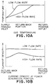
- Fig. 10A and Fig. 10B individually show the increasing condition of the gas temperature in the supply passage and the return passage (Fig. 10A), and changes in the generation current density along the gas flow passage on the surface of the power generation section (Fig. 10B), when the gas flow rate in the supply passage is decreased or not.
- gas preheating is sufficiently made by reducing the gas flow rate in the supply passage.
- the generation current density is high as a whole, with a small bias in the distribution.
- the generation current value is low as a whole and, as a result, the total power generation amount is decreased.
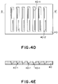
- a substrate having therein gas passages is produced from the electrode material, and on one side of which the electrolyte and the other electrode are formed.
- a hollow substrate was first produced from the electrode material, then the electrolyte and the other electrode were formed thereon.
- (La 1-x Sr x )MnO 3 having a perovskite structure was adopted which is generally used as an air electrode material of SOFC, of which powders of La 0.8 Sr 0.2 MnO 3 and La 0.9 Sr 0.1 MnO 3 having a diameter 1 - 3 ⁇ m were used.
- the substrate was produced by an extrusion method, and the power generation cell was formed on the sintered body.
- Extrusion molding can be easily carried out by using a die having the same as the cross section of the substrate.
- the thus produced molding was partially processed and then sintered to obtain a substrate same as the objective one.
- the partial processing is the same as processing of the portion corresponding to the tip and the inside of the base portion of the substrate.
- the inside at both the tip and base was partially cut (the hatched parts in Fig. 5A to Fig. 5C), where a part comprising the same material was mounted to be integrated (Fig. 5C).
- Extrusion molding requires a clayey material, and to obtain such a material, the raw material powder was mixed with the following additives.
- Raw material powder 100 Binder up to 5 Plasticizer 2 - 5 Solvent 10 - 15
- a methyl cellulose type water-soluble polymer (METOLOSE 60SH-4000 manufactured by Shin-Etsu Chemical) was used.
- the viscosity of the material for example, when the amount of water is low, the extrusion pressure becomes high, which may cause cracking during molding, or when the water content is high, it may become difficult to maintain the hollow structure.
- the mixing ratio After trials as to the mixing ratio, it was possible to produce a satisfactory molding with the above-described mixing ratio.
- an interconnector was formed by a plasma spray method.
- the spray machine used was of an air plasma spray type, and a La 0.9 Ca 0.1 CrO 3 powder was sprayed to form a film with a thickness at around 100 ⁇ m having a gas permeability on the order of 10 -7 (cc ⁇ cm/sec ⁇ (g/cm 2 )cm 2 ).
- the electrolyte and fuel electrode thin films were formed by an EVD method.
- an EVD apparatus an "electrochemical deposition apparatus" (Japanese Patent Application Laid-open No. 73546/1994) was used to form the films using yttrium chloride and zirconium chloride as raw materials at a temperature of 900°C and a reaction pressure of 1 Torr.
- a composition of zirconium oxide mixed with 8 mol % of yttrium oxide to stabilize the crystal structure (YSZ) was used. The thickness of the film-formed YSZ was about 20 ⁇ m.
- a fuel electrode was formed on the YSZ film.
- a nickel metal powder in the form of a slurry was coated on the YSZ film, and then subjected to EVD under the same conditions.
- a sheet-formed molding of each material is formed by a doctor blade method, and these sheets are appropriately laminated and thermally fused to form a green body of the hollow substrate, which is then sintered.
- the doctor blade method requires a high-viscosity slurry, and the slurry was obtained by the following mixing ratio (by weight).
- Raw material powder 100 Binder 10 - 15 Plasticizer 5 - 10 Solvent 200
- the binder poly vinyl butyral was used, di-n-butyl phthalate was used as the plasticizer, and iso-propyl alcohol was used as the solvent.
- the reason why the amounts of the binder and the plasticizer have some ranges is that the particle size and surface area differ depending on the materials used, and the properties and shrinkage of the slurry become different, which are to be appropriately adjusted. It is important in co-firing that the shrinkage of the green sheet of the subject material is made as uniform as possible and, for this purpose, the mixing ratio of the slurry is adjusted.
- a method for producing the hollow substrate of the present invention by heat pressing of the sheets is schematically shown in Fig. 6.
- Such a pressed body of the sheets was burned out and then sintered to obtain a single cell comprising the substrate and the electrolyte and electrodes formed.
- the burn out and sintering conditions were almost the same as those for the extrusion molded body described above.
- an about 100 ⁇ m thick interconnector comprising La 0.9 Ca 0.1 CrO 3 was formed on the sintered body using the plasma spray apparatus shown above. Further, the side of the substrate with insufficient interconnector formation was coated with glass paste to ensure gas sealability of the substrate.
- an electrode substrate is produced which has a structure having a plurality of passages for permeating the gas, the passages being formed in multiple stages in the inside to form supply passages and return passages, on the surface of which the electrolyte and other electrodes are formed to yield a cell. These cells are face contacted through conductors and encased in a shell to form a module.
- the tubular type has an advantage that the cell strength is high since the power generation section is formed on the surface of the support, and the electrolyte can be formed substantially thin.
- the current of power generation flows along the electrode layer , there is a large voltage drop in this portion, and high power generation characteristic cannot be achieved.
- the cell support comprises a porous electrode having a conductivity, and it can be expected to have power generation characteristics superior to the tubular type.
- the electrode used as the support is provided with gas passages formed in two stages, a gas supplied to one of the stages is preheated during passing there and, after turned back at the innermost of the support, reaches the gas passage just beneath the power generation section where the reaction is started.
- a longer dwell time in the supply passage is advantageous to achieve sufficient preheating, from the shape of the gas passages shown here, since the supply passage and the return passage are the same in cross sectional shape, the flow rates of the supplied gas in the individual passages are the same, gas preheating is insufficient only in the supply passage.
- Preheating is continued even after passing through the turn back portion and reaching the return passage where the power generation reaction is to be carried out. Therefore, the predetermined temperature is reached in this return passage, which results in a reduction in the power generation section area effectively acting for the power generation reaction, and there is a defect in that the power generation amount is decreased as a whole.
- the two types of gas required for the reaction are completely separated between inside and outside of the substrate until the reaction is completed, and because sealing is necessary for only one portion of the cell, the module can be assembled without gas leakage from the periphery of the cell as seen in the prior art flat plate type cell. Further, inside the module, connection of the individual single cells is achieved by an elastic porous conductor. Therefore, electrical connection between cells can be assured even if the flatness is not high as required in the prior art cell, and the module can be easily assembled.
- gas passages of a plurality of stages for gas supply and discharge are provided in the hollow flat plate-formed porous electrode, in this case, to reduce the flow rate of the gas in the supply passage as compared to the gas flow rate in the return passage, the number of stages of the gas passage used in the supply passage is greater than that of the return passage, or the supply passage is made larger in cross sectional area compared with the return passage. This allows sufficient preheating of the gas in the supply passage, a sufficiently preheated gas can be supplied at the time the gas passes through the turn back portion and reaches the return passage.
- part of the gas can be diffused in the substrate as the porous sintered body and supplied to the return passage to generate a power, which, in combination with the power generation reaction occurring at the turn back portion of the passage, enables uniform power generation reaction in whole substrate and then enables uniform temperature distribution in whole substrate, thereby preventing the substrate from being damaged by a thermal stress due to a temperature distribution.
- efficient gas preheating and partial gas supply by diffusion uniform power generation reaction over the entire substrate and an increased generation amount can be achieved.
- small holes communicating with the individual passage can be provided in the partition wall between the supply passage and return passage, and uniformization of power generation reaction by gas diffusion is possible even when the outer dimensions of the substrate are large and the flow passage is long.
- a solid oxide fuel cell including an electrode, a solid electrolyte, and an interconnector (4), wherein a single cell (5) includes the electrolyte (2) formed on a first main surface of a cell substrate (1) formed of a first electrode material, a second electrode (3) is formed on top of the electrolyte, and the interconnector is formed on a second main surface differing from the surface formed with the electrolyte, the cell substrate is porous, flat-formed, and has therein a plurality of flow passages of the gas corresponding to the first electrode material, the flow passage of the gas is formed in multiple stages in the substrate, forming a plurality of gas flow passages as supply passages (6) and a plurality of gas flow passages as return passages (7), these supply passage and return passage communicate with each other at a gas turn back portion (8) in the substrate, and openings of the supply passage and the return passage are located on a side surface of the substrate.
Landscapes
- Life Sciences & Earth Sciences (AREA)
- Engineering & Computer Science (AREA)
- Manufacturing & Machinery (AREA)
- Sustainable Development (AREA)
- Sustainable Energy (AREA)
- Chemical & Material Sciences (AREA)
- Chemical Kinetics & Catalysis (AREA)
- Electrochemistry (AREA)
- General Chemical & Material Sciences (AREA)
- Fuel Cell (AREA)
Applications Claiming Priority (2)
| Application Number | Priority Date | Filing Date | Title |
|---|---|---|---|
| JP212364/95 | 1995-07-28 | ||
| JP21236495 | 1995-07-28 |
Publications (3)
| Publication Number | Publication Date |
|---|---|
| EP0756347A2 true EP0756347A2 (de) | 1997-01-29 |
| EP0756347A3 EP0756347A3 (de) | 1997-03-12 |
| EP0756347B1 EP0756347B1 (de) | 1999-03-24 |
Family
ID=16621335
Family Applications (1)
| Application Number | Title | Priority Date | Filing Date |
|---|---|---|---|
| EP96112130A Expired - Lifetime EP0756347B1 (de) | 1995-07-28 | 1996-07-26 | Brennstoffzelle mit Elektrolyten aus festem Oxid |
Country Status (3)
| Country | Link |
|---|---|
| US (1) | US5786105A (de) |
| EP (1) | EP0756347B1 (de) |
| DE (1) | DE69601838T2 (de) |
Cited By (16)
| Publication number | Priority date | Publication date | Assignee | Title |
|---|---|---|---|---|
| EP1199760A1 (de) * | 1999-05-31 | 2002-04-24 | Central Research Institute of Electric Power Industry | Einzelmodul einer flachen festelektrolyt-brennstoffbatterie und diese entahltende zellenstapel |
| EP1309027A2 (de) * | 2001-10-30 | 2003-05-07 | Nissan Motor Co., Ltd. | Brennstoffzelle |
| EP1439592A2 (de) * | 2002-12-10 | 2004-07-21 | General Electric Company | Methode und Vorrichtung zum Zusammenfügen einer Festoxid-Brennstoffzelle |
| US6783880B2 (en) * | 2000-02-02 | 2004-08-31 | Haldor Topsoe A/S | Porous planar electrode support in a solid oxide fuel cell |
| WO2007134209A3 (en) * | 2006-05-11 | 2008-07-03 | Alan Devoe | Solid oxide fuel cell device comprising an elongated substrate with a hot and a cold portion |
| WO2008141171A3 (en) * | 2007-05-10 | 2009-06-25 | Alan Devoe | Fuel cell device and system |
| WO2009111771A1 (en) * | 2008-03-07 | 2009-09-11 | Alan Devoe | Fuel cell device and system |
| WO2010062639A1 (en) * | 2008-10-28 | 2010-06-03 | Alan Devoe | Fuel cell device and system |
| CN101887955A (zh) * | 2009-05-15 | 2010-11-17 | 通用汽车环球科技运作公司 | 通过基于光聚合物的过程形成的隔板 |
| US7838137B2 (en) | 2005-11-08 | 2010-11-23 | Alan Devoe | Solid oxide fuel cell device and system |
| US8153318B2 (en) | 2006-11-08 | 2012-04-10 | Alan Devoe | Method of making a fuel cell device |
| US8227128B2 (en) | 2007-11-08 | 2012-07-24 | Alan Devoe | Fuel cell device and system |
| US8597852B2 (en) | 2003-10-03 | 2013-12-03 | Lg Fuel Cell Systems Inc. | Fuel cell stack having a plurality of modules |
| US9023555B2 (en) | 2012-02-24 | 2015-05-05 | Alan Devoe | Method of making a fuel cell device |
| US9209474B2 (en) | 2009-03-06 | 2015-12-08 | Alan Devoe | Fuel cell device |
| US9437894B2 (en) | 2012-02-24 | 2016-09-06 | Alan Devoe | Method of making a fuel cell device |
Families Citing this family (29)
| Publication number | Priority date | Publication date | Assignee | Title |
|---|---|---|---|---|
| US6379485B1 (en) * | 1998-04-09 | 2002-04-30 | Siemens Westinghouse Power Corporation | Method of making closed end ceramic fuel cell tubes |
| DE69939061D1 (de) * | 1998-06-12 | 2008-08-21 | Aep Invest Inc | Keramikbrennstoffzelle |
| US7163713B2 (en) * | 1999-07-31 | 2007-01-16 | The Regents Of The University Of California | Method for making dense crack free thin films |
| KR100344936B1 (ko) * | 1999-10-01 | 2002-07-19 | 한국에너지기술연구원 | 연료극 지지체식 원통형 고체산화물 연료전지 및 그 제조방법 |
| US6387559B1 (en) * | 2000-07-18 | 2002-05-14 | Motorola, Inc. | Direct methanol fuel cell system and method of fabrication |
| DE10040282A1 (de) * | 2000-08-14 | 2002-03-07 | Robert Heggemann | Brennstoffzelle |
| DK1432861T4 (da) * | 2001-09-26 | 2012-02-13 | Fiberweb Simpsonville Inc | Apparat og fremgangsmåde til fremstilling af en ikke-vævet bane af filamenter |
| US6716549B2 (en) | 2001-12-27 | 2004-04-06 | Avista Laboratories, Inc. | Fuel cell having metalized gas diffusion layer |
| US20040035867A1 (en) * | 2002-06-27 | 2004-02-26 | S.C. Johnson Home Storage, Inc. | Container including detachable cup and built-in warming tray |
| US7282283B2 (en) * | 2002-09-28 | 2007-10-16 | Motorola, Inc. | Method and device for limiting crossover in fuel cell systems |
| US7056608B2 (en) | 2003-02-14 | 2006-06-06 | Relion, Inc. | Current collector for use in a fuel cell |
| US7014934B2 (en) * | 2003-03-18 | 2006-03-21 | Ford Motor Company | Tubular flat plate fuel cells and method of making the same |
| US6939636B2 (en) * | 2003-04-28 | 2005-09-06 | Relion, Inc. | Air cooled fuel cell module |
| US7308510B2 (en) * | 2003-05-07 | 2007-12-11 | Intel Corporation | Method and apparatus for avoiding live-lock in a multinode system |
| RU2337431C2 (ru) * | 2003-06-09 | 2008-10-27 | Сэнт-Гобэн Керамикс Энд Пластик, Инк. | Поддерживаемый батареей твердооксидный топливный элемент |
| DE112004001144T5 (de) * | 2003-06-26 | 2006-05-24 | Dai Nippon Printing Co., Ltd. | Festoxid-Brennstoffzelle |
| US7358005B2 (en) * | 2003-09-18 | 2008-04-15 | General Electric Company | Methods and apparatus for isolating solid oxide fuel cells |
| KR100717130B1 (ko) | 2005-09-30 | 2007-05-11 | 한국과학기술연구원 | 고체산화물 연료전지용 페이스트, 이를 이용한 연료극지지형 고체산화물 연료전지 및 그 제조 방법 |
| KR101154217B1 (ko) * | 2006-01-09 | 2012-06-18 | 생-고뱅 세라믹스 앤드 플라스틱스, 인코포레이티드 | 다공성 전극들을 갖는 연료 전지 부품 |
| CA2785959C (en) * | 2006-04-05 | 2013-10-29 | Saint-Gobain Ceramics & Plastics, Inc. | A sofc stack having a high temperature bonded ceramic interconnect and method for making same |
| CN102647957B (zh) | 2009-09-11 | 2015-04-29 | Gi动力公司 | 具有张开头部的锚固器 |
| US8834553B2 (en) | 2009-09-11 | 2014-09-16 | Gi Dynamics, Inc. | Anchors with biodegradable constraints |
| US9147890B2 (en) * | 2010-05-11 | 2015-09-29 | Ford Global Technologies, Llc | Fuel cell with embedded flow field |
| JP6317222B2 (ja) * | 2014-09-22 | 2018-04-25 | 日本特殊陶業株式会社 | 固体酸化物形燃料電池スタック |
| DE112018001112T5 (de) | 2017-12-13 | 2019-11-14 | Ngk Insulators, Ltd. | Brennstoffzelle und brennstoffzellenvorrichtung |
| JP6586541B1 (ja) | 2018-07-12 | 2019-10-02 | 日本碍子株式会社 | 電気化学セル、及びセルスタック装置 |
| JP6605084B1 (ja) * | 2018-07-12 | 2019-11-13 | 日本碍子株式会社 | セルスタック装置 |
| JP6605101B1 (ja) | 2018-09-07 | 2019-11-13 | 日本碍子株式会社 | マニホールド、及びセルスタック装置 |
| US11380910B2 (en) | 2018-11-06 | 2022-07-05 | Ngk Insulators, Ltd. | Fuel cell and cell stack device |
Citations (2)
| Publication number | Priority date | Publication date | Assignee | Title |
|---|---|---|---|---|
| EP0442743A1 (de) * | 1990-02-15 | 1991-08-21 | Ngk Insulators, Ltd. | Festoxidbrennstoffzelle |
| US5405712A (en) * | 1992-08-13 | 1995-04-11 | Ykk Corporation | Solid oxide fuel cell generator |
Family Cites Families (8)
| Publication number | Priority date | Publication date | Assignee | Title |
|---|---|---|---|---|
| EP0180538A1 (de) * | 1984-10-23 | 1986-05-07 | Mitsubishi Jukogyo Kabushiki Kaisha | Festelektrolytbrennstoffzelle und Verfahren zu ihrer Herstellung |
| JP2528986B2 (ja) * | 1990-02-15 | 1996-08-28 | 日本碍子株式会社 | 固体電解質型燃料電池 |
| US5292599A (en) * | 1991-09-27 | 1994-03-08 | Ngk Insulators, Ltd. | Cell units for solid oxide fuel cells and power generators using such cell units |
| JPH06196196A (ja) * | 1992-11-09 | 1994-07-15 | Fuji Electric Co Ltd | 固体電解質型燃料電池 |
| JP2826243B2 (ja) * | 1992-12-01 | 1998-11-18 | 日本電信電話株式会社 | 固体電解質型燃料電池およびその製造方法 |
| JPH06338336A (ja) * | 1993-05-31 | 1994-12-06 | Nippon Telegr & Teleph Corp <Ntt> | 導電性不均一中空平板 |
| JPH076776A (ja) * | 1993-06-16 | 1995-01-10 | Nippon Telegr & Teleph Corp <Ntt> | 固体電解質型燃料電池のスタック |
| US5549983A (en) * | 1996-01-22 | 1996-08-27 | Alliedsignal Inc. | Coflow planar fuel cell stack construction for solid electrolytes |
-
1996
- 1996-07-26 EP EP96112130A patent/EP0756347B1/de not_active Expired - Lifetime
- 1996-07-26 DE DE69601838T patent/DE69601838T2/de not_active Expired - Fee Related
- 1996-07-26 US US08/686,530 patent/US5786105A/en not_active Expired - Fee Related
Patent Citations (2)
| Publication number | Priority date | Publication date | Assignee | Title |
|---|---|---|---|---|
| EP0442743A1 (de) * | 1990-02-15 | 1991-08-21 | Ngk Insulators, Ltd. | Festoxidbrennstoffzelle |
| US5405712A (en) * | 1992-08-13 | 1995-04-11 | Ykk Corporation | Solid oxide fuel cell generator |
Non-Patent Citations (3)
| Title |
|---|
| PATENT ABSTRACTS OF JAPAN vol. 018, no. 493 (E-1606), 14 September 1994 & JP-A-06 168729 (NIPPON TELEGR & TELEPH CORP), 14 June 1994, * |
| PATENT ABSTRACTS OF JAPAN vol. 94, no. 012 & JP-A-06 338336 (NIPPON TELEGR & TELEPH CORP), 6 December 1994, * |
| PATENT ABSTRACTS OF JAPAN vol. 95, no. 001 & JP-A-07 006776 (NIPPON TELEGR & TELEPH CORP), 10 January 1995, * |
Cited By (60)
| Publication number | Priority date | Publication date | Assignee | Title |
|---|---|---|---|---|
| US7759016B2 (en) | 1999-05-31 | 2010-07-20 | Central Research Institute Of Electric Power Industry | Unit cell of flat solid oxide fuel cell and fuel cell stack comprising the same |
| EP1199760A4 (de) * | 1999-05-31 | 2004-09-29 | Central Res Inst Elect | Einzelmodul einer flachen festelektrolyt-brennstoffbatterie und diese entahltende zellenstapel |
| EP1199760A1 (de) * | 1999-05-31 | 2002-04-24 | Central Research Institute of Electric Power Industry | Einzelmodul einer flachen festelektrolyt-brennstoffbatterie und diese entahltende zellenstapel |
| US6783880B2 (en) * | 2000-02-02 | 2004-08-31 | Haldor Topsoe A/S | Porous planar electrode support in a solid oxide fuel cell |
| EP1309027A2 (de) * | 2001-10-30 | 2003-05-07 | Nissan Motor Co., Ltd. | Brennstoffzelle |
| EP1309027A3 (de) * | 2001-10-30 | 2004-06-09 | Nissan Motor Co., Ltd. | Brennstoffzelle |
| US7157169B2 (en) | 2001-10-30 | 2007-01-02 | Nissan Motor Co., Ltd. | Fuel cell |
| EP1439592A2 (de) * | 2002-12-10 | 2004-07-21 | General Electric Company | Methode und Vorrichtung zum Zusammenfügen einer Festoxid-Brennstoffzelle |
| EP1439592A3 (de) * | 2002-12-10 | 2007-10-24 | General Electric Company | Methode und Vorrichtung zum Zusammenfügen einer Festoxid-Brennstoffzelle |
| US9350031B2 (en) | 2003-10-03 | 2016-05-24 | Lg Fuel Cell Systems Inc. | Fuel cell stack having a plurality of modules |
| US8597852B2 (en) | 2003-10-03 | 2013-12-03 | Lg Fuel Cell Systems Inc. | Fuel cell stack having a plurality of modules |
| US7838137B2 (en) | 2005-11-08 | 2010-11-23 | Alan Devoe | Solid oxide fuel cell device and system |
| US9673459B2 (en) | 2005-11-08 | 2017-06-06 | Alan Devoe | Solid oxide fuel cell device |
| US7842429B2 (en) | 2005-11-08 | 2010-11-30 | Alan Devoe | Solid oxide fuel cell device and system |
| US7883816B2 (en) | 2005-11-08 | 2011-02-08 | Alan Devoe | Solid oxide fuel cell device and system, method of using and method of making |
| US7981565B2 (en) | 2005-11-08 | 2011-07-19 | Alan Devoe | Solid oxide fuel cell device and system |
| US10096846B2 (en) | 2005-11-08 | 2018-10-09 | Alan Devoe | Solid oxide fuel cell device |
| US10673081B2 (en) | 2005-11-08 | 2020-06-02 | Alan Devoe | Solid oxide fuel cell device |
| US8293415B2 (en) | 2006-05-11 | 2012-10-23 | Alan Devoe | Solid oxide fuel cell device and system |
| US9859582B2 (en) | 2006-05-11 | 2018-01-02 | Alan Devoe | Solid oxide fuel cell device and system |
| US10559839B2 (en) | 2006-05-11 | 2020-02-11 | Alan Devoe | Solid oxide fuel cell device and system |
| US8029937B2 (en) | 2006-05-11 | 2011-10-04 | Alan Devoe | Solid oxide fuel cell device and system |
| US8932776B2 (en) | 2006-05-11 | 2015-01-13 | Alan Devoe | Solid oxide fuel cell device and system |
| WO2007134209A3 (en) * | 2006-05-11 | 2008-07-03 | Alan Devoe | Solid oxide fuel cell device comprising an elongated substrate with a hot and a cold portion |
| US8153318B2 (en) | 2006-11-08 | 2012-04-10 | Alan Devoe | Method of making a fuel cell device |
| US8293417B2 (en) | 2006-11-08 | 2012-10-23 | Alan Devoe | Solid oxide fuel cell device |
| US9123937B2 (en) | 2006-11-08 | 2015-09-01 | Alan Devoe | Solid oxide fuel cell device |
| US9397346B2 (en) | 2006-11-08 | 2016-07-19 | Alan Devoe | Solid oxide fuel cell device |
| US8609290B2 (en) | 2006-11-08 | 2013-12-17 | Alan Devoe | Solid oxide fuel cell device |
| US9362572B2 (en) | 2007-05-10 | 2016-06-07 | Alan Devoe | Fuel cell device and system |
| US8257884B2 (en) | 2007-05-10 | 2012-09-04 | Alan Devoe | Method of making a fuel cell device |
| WO2008141171A3 (en) * | 2007-05-10 | 2009-06-25 | Alan Devoe | Fuel cell device and system |
| US8409764B2 (en) | 2007-05-10 | 2013-04-02 | Alan Devoe | Fuel cell device and system |
| US10312530B2 (en) | 2007-05-10 | 2019-06-04 | Alan Devoe | Fuel cell device and system |
| CN101897064A (zh) * | 2007-05-10 | 2010-11-24 | A·德沃 | 燃料电池装置和系统 |
| US8278013B2 (en) | 2007-05-10 | 2012-10-02 | Alan Devoe | Fuel cell device and system |
| JP2014038867A (ja) * | 2007-05-10 | 2014-02-27 | Alan Devoe | 燃料電池装置及びシステム |
| US8309266B2 (en) | 2007-05-10 | 2012-11-13 | Alan Devoe | Fuel cell device and system |
| US8293429B2 (en) | 2007-05-10 | 2012-10-23 | Alan Devoe | Method of making a fuel cell device |
| US8614026B2 (en) | 2007-11-08 | 2013-12-24 | Alan Devoe | Fuel cell device and system |
| US8227128B2 (en) | 2007-11-08 | 2012-07-24 | Alan Devoe | Fuel cell device and system |
| US10153496B2 (en) | 2007-11-08 | 2018-12-11 | Alan Devoe | Fuel cell device and system |
| US8962209B2 (en) | 2008-03-07 | 2015-02-24 | Alan Devoe | Fuel cell device and system |
| US9343753B2 (en) | 2008-03-07 | 2016-05-17 | Alan Devoe | Fuel cell device and system |
| EP2677582A1 (de) * | 2008-03-07 | 2013-12-25 | Alan Devoe | Brennstoffzellenvorrichtung und System |
| WO2009111771A1 (en) * | 2008-03-07 | 2009-09-11 | Alan Devoe | Fuel cell device and system |
| US8343684B2 (en) | 2008-03-07 | 2013-01-01 | Alan Devoe | Fuel cell device and system |
| US10734659B2 (en) | 2008-10-28 | 2020-08-04 | Alan Devoe | Fuel cell device and system |
| US8470493B2 (en) | 2008-10-28 | 2013-06-25 | Alan Devoe | Fuel cell device and system |
| WO2010062639A1 (en) * | 2008-10-28 | 2010-06-03 | Alan Devoe | Fuel cell device and system |
| US10062911B2 (en) | 2008-10-28 | 2018-08-28 | Alan Devoe | Fuel cell device and system |
| US9209474B2 (en) | 2009-03-06 | 2015-12-08 | Alan Devoe | Fuel cell device |
| CN101887955B (zh) * | 2009-05-15 | 2013-04-03 | 通用汽车环球科技运作公司 | 通过基于光聚合物的过程形成的隔板 |
| CN101887955A (zh) * | 2009-05-15 | 2010-11-17 | 通用汽车环球科技运作公司 | 通过基于光聚合物的过程形成的隔板 |
| US10320012B2 (en) | 2011-11-30 | 2019-06-11 | Alan Devoe | Fuel cell device |
| US9716286B2 (en) | 2012-02-24 | 2017-07-25 | Alan Devoe | Method of making a fuel cell device |
| US10355300B2 (en) | 2012-02-24 | 2019-07-16 | Alan Devoe | Method of making a fuel cell device |
| US9577281B1 (en) | 2012-02-24 | 2017-02-21 | Alan Devoe | Method of making a fuel cell device |
| US9437894B2 (en) | 2012-02-24 | 2016-09-06 | Alan Devoe | Method of making a fuel cell device |
| US9023555B2 (en) | 2012-02-24 | 2015-05-05 | Alan Devoe | Method of making a fuel cell device |
Also Published As
| Publication number | Publication date |
|---|---|
| US5786105A (en) | 1998-07-28 |
| EP0756347B1 (de) | 1999-03-24 |
| DE69601838T2 (de) | 1999-10-14 |
| EP0756347A3 (de) | 1997-03-12 |
| DE69601838D1 (de) | 1999-04-29 |
Similar Documents
| Publication | Publication Date | Title |
|---|---|---|
| EP0756347B1 (de) | Brennstoffzelle mit Elektrolyten aus festem Oxid | |
| JP5197890B2 (ja) | 固体酸化物形燃料電池セルおよび燃料電池セルスタック装置ならびに燃料電池モジュール、燃料電池装置 | |
| US6551735B2 (en) | Honeycomb electrode fuel cells | |
| JP3137177B2 (ja) | 固体電解質型燃料電池 | |
| EP2224520B1 (de) | Horizontal gestreifter festoxid-brennstoffbatteriezellenstapel und brennstoffbatterie | |
| JP2004511070A (ja) | 固体酸化物形燃料電池構成部品及び固体酸化物形燃料電池構成部品の製造方法 | |
| JP3102809B2 (ja) | 中空薄板式固体電解質燃料電池 | |
| CN101300709A (zh) | 带有整体密封和支撑物的陶瓷膜,及包括其的电化学电池和电化学电池堆 | |
| WO2009123389A1 (en) | Electrode supports and monolith type unit cells for solid oxide fuel cells and manufacturing methods of stacks using the same | |
| US6534211B1 (en) | Fuel cell having an air electrode with decreased shrinkage and increased conductivity | |
| JP5105840B2 (ja) | 平板型燃料電池のインターコネクタ及びその製法、平板型燃料電池、平板型燃料電池スタック並びにその製法 | |
| JPH08287926A (ja) | 固体電解質型燃料電池の製造方法 | |
| JP3166888B2 (ja) | 固体電解質型燃料電池のスタック | |
| JPH1074528A (ja) | 固体電解質型燃料電池およびその製造方法 | |
| JP2826243B2 (ja) | 固体電解質型燃料電池およびその製造方法 | |
| CN113488689B (zh) | 固体氧化物燃料电池堆及其制备方法 | |
| JP3966950B2 (ja) | 電気化学セル用支持体、電気化学セルおよびその製造方法 | |
| JPH09180732A (ja) | 固体電解質型燃料電池基板とその基板を用いたセル作製方法 | |
| JPH1186886A (ja) | 固体電解質型燃料電池 | |
| JP3063952B2 (ja) | 中空平板状固体電解質型燃料電池 | |
| JPH06349515A (ja) | 固体電解質型燃料電池およびその運転方法 | |
| JPH02168568A (ja) | 固体電解質型燃料電池 | |
| JPH11126617A (ja) | 固体電解質型燃料電池とその製造方法 | |
| JP2802196B2 (ja) | 燃料電池用支持体の製造方法 | |
| JPH1167244A (ja) | 中空構造の固体電解質型燃料電池及びその製造方法 |
Legal Events
| Date | Code | Title | Description |
|---|---|---|---|
| PUAI | Public reference made under article 153(3) epc to a published international application that has entered the european phase |
Free format text: ORIGINAL CODE: 0009012 |
|
| PUAL | Search report despatched |
Free format text: ORIGINAL CODE: 0009013 |
|
| 17P | Request for examination filed |
Effective date: 19960726 |
|
| AK | Designated contracting states |
Kind code of ref document: A2 Designated state(s): DE FR |
|
| AK | Designated contracting states |
Kind code of ref document: A3 Designated state(s): DE FR |
|
| 17Q | First examination report despatched |
Effective date: 19970702 |
|
| GRAG | Despatch of communication of intention to grant |
Free format text: ORIGINAL CODE: EPIDOS AGRA |
|
| GRAG | Despatch of communication of intention to grant |
Free format text: ORIGINAL CODE: EPIDOS AGRA |
|
| GRAH | Despatch of communication of intention to grant a patent |
Free format text: ORIGINAL CODE: EPIDOS IGRA |
|
| GRAH | Despatch of communication of intention to grant a patent |
Free format text: ORIGINAL CODE: EPIDOS IGRA |
|
| GRAA | (expected) grant |
Free format text: ORIGINAL CODE: 0009210 |
|
| AK | Designated contracting states |
Kind code of ref document: B1 Designated state(s): DE FR |
|
| REF | Corresponds to: |
Ref document number: 69601838 Country of ref document: DE Date of ref document: 19990429 |
|
| ET | Fr: translation filed | ||
| PLBE | No opposition filed within time limit |
Free format text: ORIGINAL CODE: 0009261 |
|
| STAA | Information on the status of an ep patent application or granted ep patent |
Free format text: STATUS: NO OPPOSITION FILED WITHIN TIME LIMIT |
|
| 26N | No opposition filed | ||
| PGFP | Annual fee paid to national office [announced via postgrant information from national office to epo] |
Ref country code: FR Payment date: 20060719 Year of fee payment: 11 |
|
| PGFP | Annual fee paid to national office [announced via postgrant information from national office to epo] |
Ref country code: DE Payment date: 20060828 Year of fee payment: 11 |
|
| PG25 | Lapsed in a contracting state [announced via postgrant information from national office to epo] |
Ref country code: DE Free format text: LAPSE BECAUSE OF NON-PAYMENT OF DUE FEES Effective date: 20080201 |
|
| REG | Reference to a national code |
Ref country code: FR Ref legal event code: ST Effective date: 20080331 |
|
| PG25 | Lapsed in a contracting state [announced via postgrant information from national office to epo] |
Ref country code: FR Free format text: LAPSE BECAUSE OF NON-PAYMENT OF DUE FEES Effective date: 20070731 |