EP0442743A1 - Festoxidbrennstoffzelle - Google Patents
Festoxidbrennstoffzelle Download PDFInfo
- Publication number
- EP0442743A1 EP0442743A1 EP91301211A EP91301211A EP0442743A1 EP 0442743 A1 EP0442743 A1 EP 0442743A1 EP 91301211 A EP91301211 A EP 91301211A EP 91301211 A EP91301211 A EP 91301211A EP 0442743 A1 EP0442743 A1 EP 0442743A1
- Authority
- EP
- European Patent Office
- Prior art keywords
- gas
- cell unit
- chamber
- combustion chamber
- dense
- Prior art date
- Legal status (The legal status is an assumption and is not a legal conclusion. Google has not performed a legal analysis and makes no representation as to the accuracy of the status listed.)
- Granted
Links
Images


Classifications
-
- H—ELECTRICITY
- H01—ELECTRIC ELEMENTS
- H01M—PROCESSES OR MEANS, e.g. BATTERIES, FOR THE DIRECT CONVERSION OF CHEMICAL ENERGY INTO ELECTRICAL ENERGY
- H01M8/00—Fuel cells; Manufacture thereof
- H01M8/24—Grouping of fuel cells, e.g. stacking of fuel cells
- H01M8/241—Grouping of fuel cells, e.g. stacking of fuel cells with solid or matrix-supported electrolytes
- H01M8/2425—High-temperature cells with solid electrolytes
-
- H—ELECTRICITY
- H01—ELECTRIC ELEMENTS
- H01M—PROCESSES OR MEANS, e.g. BATTERIES, FOR THE DIRECT CONVERSION OF CHEMICAL ENERGY INTO ELECTRICAL ENERGY
- H01M8/00—Fuel cells; Manufacture thereof
- H01M8/10—Fuel cells with solid electrolytes
- H01M8/12—Fuel cells with solid electrolytes operating at high temperature, e.g. with stabilised ZrO2 electrolyte
- H01M8/1231—Fuel cells with solid electrolytes operating at high temperature, e.g. with stabilised ZrO2 electrolyte with both reactants being gaseous or vaporised
-
- Y—GENERAL TAGGING OF NEW TECHNOLOGICAL DEVELOPMENTS; GENERAL TAGGING OF CROSS-SECTIONAL TECHNOLOGIES SPANNING OVER SEVERAL SECTIONS OF THE IPC; TECHNICAL SUBJECTS COVERED BY FORMER USPC CROSS-REFERENCE ART COLLECTIONS [XRACs] AND DIGESTS
- Y02—TECHNOLOGIES OR APPLICATIONS FOR MITIGATION OR ADAPTATION AGAINST CLIMATE CHANGE
- Y02E—REDUCTION OF GREENHOUSE GAS [GHG] EMISSIONS, RELATED TO ENERGY GENERATION, TRANSMISSION OR DISTRIBUTION
- Y02E60/00—Enabling technologies; Technologies with a potential or indirect contribution to GHG emissions mitigation
- Y02E60/30—Hydrogen technology
- Y02E60/50—Fuel cells
Definitions
- This invention relates to a solid oxide fuel cell.
- the fuel cell is an equipment capable of directly converting chemical energy possessed by fuel to electric energy. Since the fuel cell is free from the limitation of Carnot's cycle, it is an extremely promising technique in that the fuel cell essentially has a high energy conversion efficiency, and various fuels (naphtha, natural gas, methanol, coal reformed gas, heavy oil, etc.) may be used, and the public nuisance is less, and the power generating efficiency is not influenced by the scale of the equipment.
- the solid oxide fuel cell (hereinafter abbreviated as SOFC) operates at a high temperature of 1000°C or more, the activity of the electrode is very high, and the use of a noble metal catalyst such as expensive platinum is not completely required.
- the SOFC since the SOFC has a low polarization and a relatively high output voltage, the energy conversion efficiency is considerably higher than that in the other fuel cell.
- the SOFC since the SOFC is constructed with solid materials, it is stable and has a long use life.
- a cell unit for SOFC is generally comprised of an air electrode, a solid electrolyte and a fuel electrode.
- a flat plate type SOFC cell unit is large in the effective cell area per unit volume and has a bright future. It is known that a plurality of such flat plate type SOFC cell units are arranged in parallel with each other and rigidly and closely fixed to each other to form a power generation chamber, whereby an oxidizing gas and a fuel gas are supplied from one side of the power generation chamber and a burnt exhaust gas is discharged from the other side thereof.
- the cell units are rigidly and closely fixed to each other to form an airtight power generation chamber, these units are at a mutually sealed and restrained state, so that a large thermal stress occurs in an edge portion of the cell unit at a high temperature in the operation .
- electrode reaction is active in the vicinity of a supply port for the oxidizing gas and fuel gas, while electrode reaction is inactive in the vicinity of a discharge port for the exhaust gas and the temperature at this port is low, so that a large temperature gradient is caused in the power generation chamber, whereby a large thermal stress is also created.
- These thermal stresses are apt to produce cracks in the brittle fuel cell unit, and consequently the power generation efficiency lowers and the breakage of an assembly of these cell units proceeds.
- the pushing stress becomes larger and hence cracks are also apt to be produced in the brittle cell unit.
- an object of the invention to provide a solid oxide fuel cell having a high reliability and an improved durability in which the occurrence of cracks is prevented by mitigating thermal stress created in the cell unit and the power generation at each position of the fuel cell unit is made uniform by making small the temperature gradient over a region ranging from the gas supply side of the cell unit to the end portion of the power generation chamber side and the structure of the cell unit is high in the strength and stable to gas.
- a solid oxide fuel cell comprising: an electrode body, preferably plate-like, of porous ceramic having a plurality of gas flowing passages therein; a dense interconnector formed on at least one main surface of the plate-like electrode body; a dense solid electrolyte film formed on at least other main surface of the plate-like electrode body; an electrode film formed on the dense solid electrolyte film and having a polarity opposite to a polarity of the plate-like electrode body; a gas supply chamber for supplying an oxidizing gas or a fuel gas to the gas flowing passage; a dense partition member holding an end portion of a fuel cell unit at a side of the gas supply chamber; an exhaust gas combustion chamber arranged adjacent to the gas supply chamber through the dense partition member; and a partition member separating the exhaust gas combustion chamber from a power generation chamber, in which the oxidizing gas or fuel gas supplied from the gas supply chamber to the gas flowing passages is turned around an end portion of the fuel cell unit at the side of the power generation chamber and
- the dense partition member supporting the outer periphery of the fuel cell unit between the gas supply chamber and the exhaust gas combustion chamber is covered at its surface with an airtight material so as not to substantially exposure the surface of the dense partition member to the gas supply chamber and the exhaust gas combustion chamber.
- the outer periphery of the fuel cell unit is supported by a porous material having a substantially gas impermeability between the gas supply chamber and the exhaust gas combustion chamber.
- an SOFC cell unit 11 is constituted as follows. That is, as shown in Figs. 2 and 3, an elongated flat plate-like air electrode body 3 is used as a support and a film of a dense interconnector 12 is formed on a lower bottom surface of the air electrode body 3 and a film of a dense solid electrolyte 9 is formed on top surface and side surfaces of the air electrode body 3. Thus, the surrounding of the air electrode body 3 is covered with the dense films. Moreover, the interconnector 12 is extended to the dense solid electrolyte film 9 over the air electrode body 3 as shown in Fig.
- a film of a fuel electrode 10 is formed on an upper surface and side surfaces of the solid electrolyte film 9 so as not to contact with the interconnector 12 and is terminated before a porous partition member 2 separating the exhaust gas combustion chamber 7 from a power generation chamber 8 as shown in Figs. 1 and 2.
- An end of the SOFC cell unit 11 is supported by a dense partition member 1 surrounding the solid electrolyte film 9 and the interconnector 12, through which the gas supply chamber 30 for an oxygen containing gas such as air or the like is separated from the exhaust gas combustion chamber 7.
- the SOFC cell unit 11 is softly supported by the porous partition member 2 separating the exhaust gas combustion chamber 7 from the power generation chamber 8.
- the flat plate-like air electrode body 3 may be made from doped or undoped LaMnO3, CaMnO3, LaNiO3, LaCoO3, LaCrO3 or the like, among which LaMnO3 doped with strontium is preferable.
- the dense solid electrolyte film 9 may generally be made from zirconia stabilized with yttria or the like.
- the fuel electrode film 10 is generally made from nickel-zirconia cermet or cobalt-zirconia cermet.
- a plurality of gas flowing passages 4A, 4B In the inside of the flat plate-like air electrode body 3 is formed a plurality of gas flowing passages 4A, 4B, in which an inlet port 16 and a closed member 5 are alternately arranged in the ends of these passages facing to the gas supply chamber 30.
- the oxidizing gas is fed from the each of the gas inlet portions 16 through each of the gas flowing passages 4A toward the end of the SOFC cell unit at the side of the power generation chamber and turned around the end in a direction opposite to the flowing direction and again passed through each of the gas flowing passages 4B toward the gas supply chamber 30 as shown by an arrow E.
- the closing member 5 is disposed in the end of the gas flowing passage 4B at the side of the gas supply chamber 30 and also a gas discharge port 6 facing the exhaust gas combustion chamber 7 is formed in the gas flowing passage 4B. Therefore, the oxidizing gas gives an oxygen ion to the fuel electrode film 10 through the air electrode body 3 and the solid electrolyte film 9 during the passing through the gas flowing passages 4A, 4B, which ion reacts with fuel on the fuel electrode film 10 to contribute power generation. A waste oxidizing gas having a reduced oxygen concentration is discharged from the gas discharge port 6 to the exhaust gas combustion chamber 7.
- the porous partition member 2 separating the exhaust gas combustion chamber 7 from the power generation chamber 8 is designed to produce a flowing of fuel gas toward the exhaustion gas combustion chamber 7 at a slight pressure difference between the power generation chamber 8 and the exhaust gas combustion chamber 7, whereby the backward flowing of oxidizing gas from the exhaust gas combustion chamber 7 to the power generation chamber 8 is prevented.
- fuel gas is passed in the power generation chamber 8 for use in power generation as shown by an arrow F, and a mixed gas of steam and carbon dioxide gas produced by the reaction with the oxygen ion as well as unreacted fuel gas is passed through a gap between the porous partition member 2 and the SOFC cell unit 11 toward the exhaust gas combustion chamber 7, at where the mixed gas is burnt by contacting with the waste oxidizing gas to preheat a fresh oxidizing gas passing through the gas flowing passages 4A, 4B.
- the oxidizing gas produces oxygen ion at the interface between the air electrode body 3 and the solid electrolyte film 9, which moves through the solid electrolyte film 9 to the fuel electrode film 10.
- the oxygen ion reacts with the fuel gas to emit electron to the fuel electrode film 10.
- a power is taken out by connecting a load between the interconnector 12 connected to the air electrode as a positive pole and the fuel electrode film 10 as a negative pole.
- the interconnector 11 of the upper SOFC cell unit 11 is connected to the fuel electrode film 9 of the lower SOFC cell unit 11 through a nickel felt 14 to conduct series connection of these SOFC cell units, while the fuel electrode films 10 of the adjoining upper SOFC cell units 11 and the adjoining lower SOFC cell units 11 are connected to each other through a respective nickel felt 13 to conduct parallel connection of these units 11.
- the embodiment of Fig. 4 uses four SOFC cell units 11 for convenience' sake, the number of SOFC cell units used may freely be changed.
- the solid oxide fuel cell of the above illustrated embodiment develops the following effects.
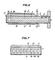
- Fig. 5 is shown another embodiment of the SOFC cell unit 21 according to the invention.
- Fig. 6 is a sectional view taken along a line VI-VI of Fig. 5
- Fig. 7 is a sectional view taken along a line VII-VII of Fig. 5.
- the partition members 1 and 2 and nickel felt 24 are omitted for convenience' sake.
- the whole structure of the SOFC cell unit 21 shown in Fig. 5 to 7 are substantially the same as in the SOFC cell unit 11 of Figs. 1 to 3, so that the explanation on the same parts is omitted.
- a fuel electrode film 20 is formed on only the main surface of the cell unit (upper side surface in Figs. 6 and 7) but does not extend to the side surface of the cell unit.
- nickel felts 24 are arranged so as to contact with the lower surface of the interconnector 12 and the upper surface of the fuel electrode film 20 in the SOFC cell unit 21 as shown in Fig. 6.
- the connection between the SOFC cell units is series.
- the fuel electrode films 20 of the adjoining SOFC cell units 21 in the lateral direction are connected to each other with a common nickel felt 24, whereby the connection between the adjoining stacks is rendered into parallel connection.
- the fuel electrode films 20 located at the upper ends of the stacks may be connected to each other with a common metal plate, while the interconnectors 12 located at he lower ends of the stacks may be connected to each other with another common metal plate.
- the fuel electrode film 20 is not formed on the side surface of the SOFC cell unit 21, only the solid electrolyte film 9 is exposed at the side surface, so that there is no risk of electrically forming a short circuit between the fuel electrode film 20 and the interconnector 12, and hence the practicality is more enhanced.
- gas flowing passages 4A, 4B for the oxidizing gas are arranged in the air electrode body 3 in the longitudinal direction of the cell unit as shown in Fig. 5, among which the closing member 5 is arranged to each of the upper two passages and the lower two passages 4B, while gas supply ports 16 are arranged in the four passages 4A at the central portion of the air electrode body 3.
- the oxidizing gas is first supplied from the gas supply ports 16 into the gas flowing passages 4A and divided at the ends of the passages 4A in up and down directions and then entered into the gas flowing passages 4B.
- the first and second embodiments may be variously modified as follows.
- the cell unit 11 is horizontally supported in Fig. 1, the whole of the SOFC itself may be vertical or may be inclined at a given angle.
- the plane shape of the flat plate-like SOFC cell unit may be triangular, hexagonal, circular or the like in addition to square and rectangular. Furthermore, the plate shape of the SOFC cell unit may be wavy, conical, pyramidal, spherical or the like in addition to flat.
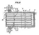
- Figs. 8 and 9 a third embodiment of the SOFC cell unit 31 according to the invention, in which Fig. 9 is a sectional view taken along a line IX-IX of Fig. 8.
- This embodiment has the same structure as in the first embodiment of Figs. 1 to 3 except for the supporting of the SOFC cell unit at its one end.
- the supporting of the SOFC cell unit 31 is made as follows.
- an end of the SOFC cell unit 31 is inserted into a hole 32a formed in an airtight partition member 32 and a porous member 33 is filled in a space between the the hole 32a and the outer peripheral surface of the SOFC cell unit 31, whereby the SOFC cell unit 31 is softly supported.
- the gas supply chamber 30 for the oxidizing gas is defined at the left side of the airtight partition member 32 and the porous member 33, while the exhaust gas combustion chamber 7 is defined at right side thereof as shown in Figs. 8 and 9.
- an airtight wall member 34 is disposed onto the surface of the airtight partition member 24 facing to the gas supply chamber 30 so as to cover the surface of the porous member 33, whereby the surface of the porous member 33 is not exposed to the gas supply chamber 30.
- the edge portion of the airtight wall member 34 in the vicinity of the outer peripheral surface of the SOFC cell unit 31 has a slant portion 34a, and the tip of the slant portion 34a contacts with the outer peripheral surface of the SOFC cell unit 31.
- the slant portion 34a substantially comes into contact with the SOFC cell unit 31 without fixing, so that it is permitted to locally produce a gap between the SOFC cell unit 31 and the slant portion 34a at the contacted region.
- an airtight slant projecting portion 35 is formed on the outer peripheral surface of the SOFC cell unit 31 facing to the exhaust gas combustion chamber 7 so as to cover the surface of the porous member 33 facing to the exhaust gas combustion chamber 7, whereby the exposure of the surface of the porous member 33 to the exhaust gas combustion chamber 7 is prevented.
- the porous partition member 2 is arranged so as to separate the exhaust gas combustion chamber 7 from the power generation chamber 8, whereby the SOFC cell unit 31 is also softly supported.
- porous member 33 use may be made of ceramic fiber felt, ceramic fiber board, refractory brick, insulated castable and the like.
- a material of the airtight wall member 34 use may be made of refractory cements and mortars of alumina, mullite, zirconia and the like.
- the slant projecting portion 35 may be formed by adhering, bonding or sticking the same material as in the solid electrolyte film 9 to the outer peripheral surface of the SOFC cell unit, or may be formed by subjecting the solid electrolyte film having a thicker thickness for the SOFC cell unit to a cutting work.
- the airtight wall member 34 with the slant portion 34a is integrally united with the airtight partition member 32, which may be made from an insulated material such as alumina, mullite, zirconia or the like. Furthermore, the airtight partition member 34 with the slant portion 34a may be formed from a refractory cement onto the surfaces of the airtight partition member 32 and the porous member 33.
- the solid oxide fuel cell comprised of the SOFC cell unit having the above structure has the same effect as in the first embodiment of Figs. 1 to 3 and further develops the following effects.
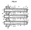
- Fig. 10 a stack formed by connecting a plurality of SOFC cell units 41 to each other.
- the SOFC cell unit 41 used in the illustrated embodiment has substantially the same structure as in the embodiment of Figs. 8 and 9.
- this embodiment has a unique partition structure for sealing between the gas supply chamber 30 and the exhaust gas combustion chamber 7 as mentioned later.
- a porous member 42 is filled between the adjoining SOFC cell units 41 instead of the airtight partition member 32 shown in Fig. 9, whereby the outer peripheral surface of the SOFC cell unit 42 is covered at its one end with the porous member 42 to support the SOFC cell unit 42.
- an airtight member That is, an airtight slant projecting member 43 or 44 is arranged on each of the SOFC cell units 42. Then, these airtight slant projecting members 43 and 44 in the adjoining upper and lower SOFC cell units are contacted with each other or separated from each other at a slight gap, whereby the surface of the porous member 42 is substantially covered so as not to expose to the side of the exhaust gas combustion chamber 7.
- an airtight pushing member 45 having a triangular shape in section is arranged on the surface of the porous member 42 facing to the gas supply chamber 30 and an edge of the airtight pushing member 45 is contacted with the outer peripheral surface of the SOFC cell unit or fixed to the porous member 42 at a slight gap to the SOFC cell unit, whereby the surface of the porous member 42 is substantially covered so as not to expose to the gas supply chamber 30.
- the airtight pushing member 45 is preferably made from refractory cement, mortar or the like.
- a small protrusion (not shown) is formed on the outer peripheral surface at the end of the SOFC cell unit 42, whereby the airtight pushing member 45 may be fastened so as not to cause the position shift outward the stack.
- the SOFC of Fig. 10 has the same effect as in the SOFC of Figs 8 and 9. Furthermore, the SOFC cell unit 42 is supported by the porous member 42 without using the airtight partition member 32 (Fig. 9), so that the structure becomes more simple and the enhancement of spatial stacking degree for SOFC cell unit becomes easier.
- a slant projecting portion may be formed on the outer peripheral surface of the SOFC cell unit so as to cover the surface of the porous member 42.
- the surface of the porous member 42 may be covered by thinly applying the refractory cement, mortar or the like.
- water-glass, colloidal filter or metal foil such as iron or the like may be used instead of the airtight pushing member 45.
- Fig. 11 is shown another embodiment of the SOFC cell unit 51 according to the invention, which is a modified embodiment of Fig. 9.
- a porous material having substantially a gas impermeability is used as the porous member 32 filled in a space between the surface 32a of the airtight partition member 32 and the outer peripheral surface of the SOFC cell unit 51.
- the porous material is preferably formed by foaming glass beads or the like in the ceramic such as alumina, silica or the like.
- the SOFC cell unit 51 is softly supported by the porous member 33 having substantially a gas impermeability, and at the same time the sealing between the gas supply chamber 30 and the exhaust gas combustion chamber 7 can sufficiently be attained by the porous member 33.
- the SOFC of Fig. 11 has the same effects as in the embodiment of Fig. 9.
- the supporting structure becomes more simple, which is more favorable from a viewpoint of the manufacture.
- the shape, size and structure of the porous member as well as the shape and structure of the airtight member covering the surface of the porous member may variously be changed, if necessary.
- the cell unit is supported at its one end portion facing to the gas supply chamber by the dense partition member, so that the excessive stress is not caused in the cell unit from a viewpoint of the structure, which is entirely different from the conventional technique of rigidly fixing the outer peripheral surface of the cell unit.
- the exhaust gas combustion chamber is arranged adjacent to the gas supply chamber and separated from the power generation chamber through the partition member, whereby the fuel gas is fed from the power generation chamber to the exhaust gas combustion chamber, while the oxidizing gas is fed to the gas flowing passages in the plate-like electrode body and discharged from the gas outlet port to the exhaust gas combustion chamber. Therefore, the oxidizing gas and the fuel gas are not mixed before the exhaust gas combustion chamber because the oxidizing gas passage and the fuel gas passage are clearly partitioned in view of the structure of the cell unit, so that the fixing for sealing the cell unit as in the conventional technique is not necessary. As a result, there is caused no stress resulted from the fixing and sealing, and the reliability as a structural body is high. Further, the uniformization of power generation over the whole of the SOFC cell unit and the power generation efficiency can be improved.
- the oxidizing gas leaked from the gas supply chamber to the exhaust gas combustion chamber merely contacts with a gas having a fuel gas concentration considerably reduced in the passing through the power generation chamber, so that excessively local power generation of the SOFC cell unit can be prevented and hence the durability is improved.
- the SOFC cell unit has a box-type multi-channel structure, so that the structural strength of the cell unit itself can be increased.
- the outer periphery of the cell unit is softly supported between the gas supply chamber and the exhaust gas combustion chamber by the porous member, so that the excessive stress is hardly created and can be mitigated in view of the structure, and consequently the damage of the SOFC cell unit can effectively be prevented.
- the surface of the porous member is substantially covered with the airtight member so as not to expose to the porous member to the gas supply chamber and the exhaust gas combustion chamber or the porous member is made from a porous material having substantially a gas impermeability, the leakage of a fresh gas from the gas supply chamber to the exhaust gas combustion chamber hardly occurs and the sealing is complete.
Applications Claiming Priority (4)
| Application Number | Priority Date | Filing Date | Title |
|---|---|---|---|
| JP2032381A JP2528986B2 (ja) | 1990-02-15 | 1990-02-15 | 固体電解質型燃料電池 |
| JP32381/90 | 1990-02-15 | ||
| JP75606/90 | 1990-03-27 | ||
| JP2075606A JP2531824B2 (ja) | 1990-03-27 | 1990-03-27 | 固体電解質型燃料電池 |
Publications (2)
| Publication Number | Publication Date |
|---|---|
| EP0442743A1 true EP0442743A1 (de) | 1991-08-21 |
| EP0442743B1 EP0442743B1 (de) | 1996-08-28 |
Family
ID=26370944
Family Applications (1)
| Application Number | Title | Priority Date | Filing Date |
|---|---|---|---|
| EP91301211A Expired - Lifetime EP0442743B1 (de) | 1990-02-15 | 1991-02-14 | Festoxidbrennstoffzelle |
Country Status (4)
| Country | Link |
|---|---|
| US (1) | US5185219A (de) |
| EP (1) | EP0442743B1 (de) |
| CA (1) | CA2036259C (de) |
| DE (1) | DE69121601T2 (de) |
Cited By (8)
| Publication number | Priority date | Publication date | Assignee | Title |
|---|---|---|---|---|
| EP0756347A2 (de) * | 1995-07-28 | 1997-01-29 | Nippon Telegraph And Telephone Corporation | Brennstoffzelle mit Elektrolyten aus festem Oxid |
| GB2348315A (en) * | 1999-03-18 | 2000-09-27 | Sofco | Solid oxide fuel cell burner systems an methods of generating heat therefrom |
| EP1199760A1 (de) * | 1999-05-31 | 2002-04-24 | Central Research Institute of Electric Power Industry | Einzelmodul einer flachen festelektrolyt-brennstoffbatterie und diese entahltende zellenstapel |
| EP1215743A2 (de) * | 2000-12-15 | 2002-06-19 | Delphi Technologies, Inc. | Fluidverteilungssystem für Festoxidbrennstoffzellen |
| EP1391955A2 (de) * | 2002-08-21 | 2004-02-25 | General Electric Company | Fluidleitungen für eine Energieerzeugungsvorrichtung |
| WO2004102706A2 (en) | 2003-04-04 | 2004-11-25 | Versa Power Systems, Ltd. | Solid oxide fuel cell stack with floating cells |
| WO2010005781A1 (en) * | 2008-07-08 | 2010-01-14 | Siemens Energy, Inc. | Solid oxide fuel cell with transitioned cross-section for improved anode gas management at the open end |
| WO2010136214A1 (en) * | 2009-05-28 | 2010-12-02 | Ezelleron Gmbh | Oxide-ceramic high-temperature fuel cell |
Families Citing this family (28)
| Publication number | Priority date | Publication date | Assignee | Title |
|---|---|---|---|---|
| JPH0668900A (ja) * | 1992-08-13 | 1994-03-11 | Yoshida Kogyo Kk <Ykk> | 固体電解質型燃料電池発電装置 |
| ATE189560T1 (de) * | 1994-03-21 | 2000-02-15 | Ztek Corp | Elektrochemischer konverter mit optimaler druckverteilung |
| US5932366A (en) * | 1994-09-03 | 1999-08-03 | Forschungszentrum Julich Gmbh | Solid electrolyte high temperature fuel cell |
| US5514486A (en) * | 1995-09-01 | 1996-05-07 | The Regents Of The University Of California, Office Of Technology Transfer | Annular feed air breathing fuel cell stack |
| US5595834A (en) * | 1995-09-01 | 1997-01-21 | The Regents Of The University Of Calif. | Annular feed air breathing fuel cell stack |
| US6054229A (en) * | 1996-07-19 | 2000-04-25 | Ztek Corporation | System for electric generation, heating, cooling, and ventilation |
| US6326096B1 (en) | 1998-02-04 | 2001-12-04 | Gas Research Institute | Solid oxide fuel cell interconnector |
| US6054231A (en) * | 1998-07-24 | 2000-04-25 | Gas Research Institute | Solid oxide fuel cell interconnector |
| US6280866B1 (en) | 1999-02-23 | 2001-08-28 | Northern Research & Engineering Corporation | Fuel cell flow distributor design for improving durability and performance |
| US6416897B1 (en) * | 2000-09-01 | 2002-07-09 | Siemens Westinghouse Power Corporation | Tubular screen electrical connection support for solid oxide fuel cells |
| WO2003005462A2 (en) * | 2001-01-05 | 2003-01-16 | Georgia Tech Research Corporation | Hybrid monolithic fuel cell |
| EP1246276A3 (de) | 2001-03-26 | 2004-01-14 | Wilson Greatbatch Ltd. | Verbindungsschmelzsicherung |
| US6772501B2 (en) * | 2001-07-23 | 2004-08-10 | Itn Energy Systems, Inc. | Apparatus and method for the design and manufacture of thin-film electrochemical devices |
| DE602004030501D1 (de) * | 2003-02-28 | 2011-01-27 | Kyocera Corp | Brennstoffzelle |
| US7014934B2 (en) * | 2003-03-18 | 2006-03-21 | Ford Motor Company | Tubular flat plate fuel cells and method of making the same |
| DE102005011669A1 (de) * | 2004-05-28 | 2006-09-21 | Siemens Ag | Hochtemperatur-Festelektrolyt-Brennstoffzelle und damit aufgebaute Brennstoffzellenanlage |
| AU2006311545B2 (en) * | 2005-11-08 | 2011-11-17 | Alan Devoe | Solid oxid fuel cell device comprising an elongated substrate with a hot and a cold portion |
| US8153318B2 (en) | 2006-11-08 | 2012-04-10 | Alan Devoe | Method of making a fuel cell device |
| US8029937B2 (en) | 2006-05-11 | 2011-10-04 | Alan Devoe | Solid oxide fuel cell device and system |
| US8278013B2 (en) | 2007-05-10 | 2012-10-02 | Alan Devoe | Fuel cell device and system |
| US8227128B2 (en) * | 2007-11-08 | 2012-07-24 | Alan Devoe | Fuel cell device and system |
| US8343684B2 (en) | 2008-03-07 | 2013-01-01 | Alan Devoe | Fuel cell device and system |
| US8470493B2 (en) * | 2008-10-28 | 2013-06-25 | Alan Devoe | Fuel cell device and system |
| US20110117471A1 (en) * | 2009-11-16 | 2011-05-19 | Alan Devoe | Fuel cell device |
| JP4955830B1 (ja) * | 2010-12-13 | 2012-06-20 | 日本碍子株式会社 | 固体酸化物形燃料電池 |
| EP3136489B1 (de) | 2011-11-30 | 2019-03-20 | Alan Devoe | Brennstoffzellenelement |
| JP6219856B2 (ja) | 2012-02-24 | 2017-10-25 | アラン・デヴォー | 燃料電池デバイスを作製する方法 |
| US9023555B2 (en) | 2012-02-24 | 2015-05-05 | Alan Devoe | Method of making a fuel cell device |
Citations (2)
| Publication number | Priority date | Publication date | Assignee | Title |
|---|---|---|---|---|
| GB2148044A (en) * | 1983-10-12 | 1985-05-22 | Us Energy | Solid state oxide fuel cell |
| EP0286360A2 (de) * | 1987-04-06 | 1988-10-12 | Westinghouse Electric Corporation | Selbsttragende Elektrode mit integrierter Gaszufuhrleitung |
Family Cites Families (3)
| Publication number | Priority date | Publication date | Assignee | Title |
|---|---|---|---|---|
| US4490444A (en) * | 1980-12-22 | 1984-12-25 | Westinghouse Electric Corp. | High temperature solid electrolyte fuel cell configurations and interconnections |
| US4395468A (en) * | 1980-12-22 | 1983-07-26 | Westinghouse Electric Corp. | Fuel cell generator |
| EP0275356B1 (de) * | 1984-10-23 | 1991-06-05 | Mitsubishi Jukogyo Kabushiki Kaisha | Festelektrolytbrennstoffzelle und Verfahren zu ihrer Herstellung |
-
1991
- 1991-02-04 US US07/649,988 patent/US5185219A/en not_active Expired - Fee Related
- 1991-02-13 CA CA002036259A patent/CA2036259C/en not_active Expired - Fee Related
- 1991-02-14 EP EP91301211A patent/EP0442743B1/de not_active Expired - Lifetime
- 1991-02-14 DE DE69121601T patent/DE69121601T2/de not_active Expired - Fee Related
Patent Citations (2)
| Publication number | Priority date | Publication date | Assignee | Title |
|---|---|---|---|---|
| GB2148044A (en) * | 1983-10-12 | 1985-05-22 | Us Energy | Solid state oxide fuel cell |
| EP0286360A2 (de) * | 1987-04-06 | 1988-10-12 | Westinghouse Electric Corporation | Selbsttragende Elektrode mit integrierter Gaszufuhrleitung |
Cited By (21)
| Publication number | Priority date | Publication date | Assignee | Title |
|---|---|---|---|---|
| EP0756347A3 (de) * | 1995-07-28 | 1997-03-12 | Nippon Telegraph And Telephone Corporation | Brennstoffzelle mit Elektrolyten aus festem Oxid |
| US5786105A (en) * | 1995-07-28 | 1998-07-28 | Nippon Telegraph And Telephone Public Corporation | Solid oxide fuel cell |
| EP0756347A2 (de) * | 1995-07-28 | 1997-01-29 | Nippon Telegraph And Telephone Corporation | Brennstoffzelle mit Elektrolyten aus festem Oxid |
| GB2348315A (en) * | 1999-03-18 | 2000-09-27 | Sofco | Solid oxide fuel cell burner systems an methods of generating heat therefrom |
| EP1199760A4 (de) * | 1999-05-31 | 2004-09-29 | Central Res Inst Elect | Einzelmodul einer flachen festelektrolyt-brennstoffbatterie und diese entahltende zellenstapel |
| EP1199760A1 (de) * | 1999-05-31 | 2002-04-24 | Central Research Institute of Electric Power Industry | Einzelmodul einer flachen festelektrolyt-brennstoffbatterie und diese entahltende zellenstapel |
| US7759016B2 (en) | 1999-05-31 | 2010-07-20 | Central Research Institute Of Electric Power Industry | Unit cell of flat solid oxide fuel cell and fuel cell stack comprising the same |
| EP1215743A3 (de) * | 2000-12-15 | 2007-08-01 | Delphi Technologies, Inc. | Fluidverteilungssystem für Festoxidbrennstoffzellen |
| EP1215743A2 (de) * | 2000-12-15 | 2002-06-19 | Delphi Technologies, Inc. | Fluidverteilungssystem für Festoxidbrennstoffzellen |
| EP1391955A3 (de) * | 2002-08-21 | 2005-06-08 | General Electric Company | Fluidleitungen für eine Energieerzeugungsvorrichtung |
| EP1391955A2 (de) * | 2002-08-21 | 2004-02-25 | General Electric Company | Fluidleitungen für eine Energieerzeugungsvorrichtung |
| WO2004102706A3 (en) * | 2003-04-04 | 2008-01-03 | Versa Power Systems Ltd | Solid oxide fuel cell stack with floating cells |
| US7553579B2 (en) | 2003-04-04 | 2009-06-30 | Versa Power Systems Ltd. | Solid oxide fuel cell stack with floating cells |
| WO2004102706A2 (en) | 2003-04-04 | 2004-11-25 | Versa Power Systems, Ltd. | Solid oxide fuel cell stack with floating cells |
| WO2010005781A1 (en) * | 2008-07-08 | 2010-01-14 | Siemens Energy, Inc. | Solid oxide fuel cell with transitioned cross-section for improved anode gas management at the open end |
| CN102089919A (zh) * | 2008-07-08 | 2011-06-08 | 西门子能源公司 | 具有过渡横部段以改进开口端处的阳极气体管理的固体氧化物燃料电池 |
| US8097384B2 (en) | 2008-07-08 | 2012-01-17 | Siemens Energy, Inc. | Solid oxide fuel cell with transitioned cross-section for improved anode gas management at the open end |
| WO2010136214A1 (en) * | 2009-05-28 | 2010-12-02 | Ezelleron Gmbh | Oxide-ceramic high-temperature fuel cell |
| CN102449839A (zh) * | 2009-05-28 | 2012-05-09 | 埃兹勒隆股份有限公司 | 氧化物陶瓷高温燃料电池 |
| CN102449839B (zh) * | 2009-05-28 | 2017-02-22 | 埃兹勒隆股份有限公司 | 氧化物陶瓷高温燃料电池 |
| US9583772B2 (en) | 2009-05-28 | 2017-02-28 | Ezelleron Gmbh | Oxide-ceramic high-temperature fuel cell |
Also Published As
| Publication number | Publication date |
|---|---|
| EP0442743B1 (de) | 1996-08-28 |
| DE69121601D1 (de) | 1996-10-02 |
| CA2036259C (en) | 1994-04-26 |
| CA2036259A1 (en) | 1991-08-16 |
| US5185219A (en) | 1993-02-09 |
| DE69121601T2 (de) | 1997-02-06 |
Similar Documents
| Publication | Publication Date | Title |
|---|---|---|
| EP0442743B1 (de) | Festoxidbrennstoffzelle | |
| US4910100A (en) | Solid electrolyte fuel cell | |
| EP0355420B1 (de) | Brennstoffzelle mit einem festen Elektrolyten | |
| US8026011B2 (en) | Fuel cell assembly | |
| JP4578114B2 (ja) | 燃料電池 | |
| US4770955A (en) | Solid electrolyte fuel cell and assembly | |
| CA1231127A (en) | Solid oxide fuel cell having monolithic cross flow core and manifolding | |
| EP0442741B1 (de) | Festoxidbrennstoffzelle | |
| US5063122A (en) | Fuel cell assembly comprising permanently combined fuel cells | |
| JP3516325B2 (ja) | ハニカム構造固体電解質型燃料電池 | |
| JP2005100687A (ja) | 燃料電池 | |
| EP1508932B1 (de) | Festelektrolytbrennstoffzellenvorrichtung | |
| JPH0737595A (ja) | 固体電解質型燃料電池 | |
| US7470480B2 (en) | Solid electrolyte fuel-cell device | |
| JP4374086B2 (ja) | 電気化学セルユニット及び電気化学セル | |
| JP2531824B2 (ja) | 固体電解質型燃料電池 | |
| JPH03129675A (ja) | 固体電解質型燃料電池 | |
| JP2005085520A (ja) | 固体酸化物形燃料電池 | |
| JP3929136B2 (ja) | 電気化学セルおよび電気化学装置 | |
| JP2528986B2 (ja) | 固体電解質型燃料電池 | |
| JP4418196B2 (ja) | 燃料電池モジュール | |
| JP2698481B2 (ja) | 発電装置 | |
| JP4481580B2 (ja) | 固体電解質形燃料電池組立体 | |
| JPH02168568A (ja) | 固体電解質型燃料電池 | |
| JP2783926B2 (ja) | 固体電解質型燃料電池の単電池及びこれを用いた発電装置 |
Legal Events
| Date | Code | Title | Description |
|---|---|---|---|
| PUAI | Public reference made under article 153(3) epc to a published international application that has entered the european phase |
Free format text: ORIGINAL CODE: 0009012 |
|
| AK | Designated contracting states |
Kind code of ref document: A1 Designated state(s): BE DE FR GB |
|
| 17P | Request for examination filed |
Effective date: 19910829 |
|
| 17Q | First examination report despatched |
Effective date: 19930730 |
|
| GRAH | Despatch of communication of intention to grant a patent |
Free format text: ORIGINAL CODE: EPIDOS IGRA |
|
| GRAH | Despatch of communication of intention to grant a patent |
Free format text: ORIGINAL CODE: EPIDOS IGRA |
|
| GRAA | (expected) grant |
Free format text: ORIGINAL CODE: 0009210 |
|
| AK | Designated contracting states |
Kind code of ref document: B1 Designated state(s): BE DE FR GB |
|
| REF | Corresponds to: |
Ref document number: 69121601 Country of ref document: DE Date of ref document: 19961002 |
|
| ET | Fr: translation filed | ||
| PLBE | No opposition filed within time limit |
Free format text: ORIGINAL CODE: 0009261 |
|
| STAA | Information on the status of an ep patent application or granted ep patent |
Free format text: STATUS: NO OPPOSITION FILED WITHIN TIME LIMIT |
|
| 26N | No opposition filed | ||
| PGFP | Annual fee paid to national office [announced via postgrant information from national office to epo] |
Ref country code: GB Payment date: 19980204 Year of fee payment: 8 |
|
| PGFP | Annual fee paid to national office [announced via postgrant information from national office to epo] |
Ref country code: FR Payment date: 19980213 Year of fee payment: 8 |
|
| PGFP | Annual fee paid to national office [announced via postgrant information from national office to epo] |
Ref country code: DE Payment date: 19980217 Year of fee payment: 8 |
|
| PGFP | Annual fee paid to national office [announced via postgrant information from national office to epo] |
Ref country code: BE Payment date: 19980218 Year of fee payment: 8 |
|
| PG25 | Lapsed in a contracting state [announced via postgrant information from national office to epo] |
Ref country code: GB Free format text: LAPSE BECAUSE OF NON-PAYMENT OF DUE FEES Effective date: 19990214 |
|
| PG25 | Lapsed in a contracting state [announced via postgrant information from national office to epo] |
Ref country code: BE Free format text: LAPSE BECAUSE OF NON-PAYMENT OF DUE FEES Effective date: 19990228 |
|
| BERE | Be: lapsed |
Owner name: NGK INSULATORS LTD Effective date: 19990228 |
|
| GBPC | Gb: european patent ceased through non-payment of renewal fee |
Effective date: 19990214 |
|
| PG25 | Lapsed in a contracting state [announced via postgrant information from national office to epo] |
Ref country code: FR Free format text: LAPSE BECAUSE OF NON-PAYMENT OF DUE FEES Effective date: 19991029 |
|
| PG25 | Lapsed in a contracting state [announced via postgrant information from national office to epo] |
Ref country code: DE Free format text: LAPSE BECAUSE OF NON-PAYMENT OF DUE FEES Effective date: 19991201 |
|
| REG | Reference to a national code |
Ref country code: FR Ref legal event code: ST |