EP0755784A2 - Machine d'impression de feuilles - Google Patents
Machine d'impression de feuilles Download PDFInfo
- Publication number
- EP0755784A2 EP0755784A2 EP96111893A EP96111893A EP0755784A2 EP 0755784 A2 EP0755784 A2 EP 0755784A2 EP 96111893 A EP96111893 A EP 96111893A EP 96111893 A EP96111893 A EP 96111893A EP 0755784 A2 EP0755784 A2 EP 0755784A2
- Authority
- EP
- European Patent Office
- Prior art keywords
- sheet
- printing
- transport path
- printing units
- sheets
- Prior art date
- Legal status (The legal status is an assumption and is not a legal conclusion. Google has not performed a legal analysis and makes no representation as to the accuracy of the status listed.)
- Granted
Links
Images


Classifications
-
- B—PERFORMING OPERATIONS; TRANSPORTING
- B41—PRINTING; LINING MACHINES; TYPEWRITERS; STAMPS
- B41F—PRINTING MACHINES OR PRESSES
- B41F21/00—Devices for conveying sheets through printing apparatus or machines
Definitions
- the invention relates to a sheet printing machine with a plurality of printing units arranged one behind the other along a sheet transport path.
- the invention has for its object to provide a sheet printing machine suitable for successive face and back printing with several printing units, which has the smallest possible overall length.
- This object is achieved in a generic sheet printing machine according to the invention by a transport device which transports the sheets back following a transport along the sheet transport path via a return transport path which is essentially opposite to the sheet transport path.
- further printing units are provided which are arranged one behind the other along the return transport path. Which side of the returned sheets the other printing units are arranged in depends on whether the sheets are in place reversal of the direction of transport or whether they are transported back in a substantially constant position. The latter alternative is particularly suitable for thicker papers.
- the return transport can either be carried out by the same transport device that transports the sheets for straight printing, or a separate return transport device is used, which enables a modular construction of the printing press.
- both the above embodiment with further printing units and an embodiment are possible in which, apart from the printing units, no further printing units are required along the sheet transport path.
- the return transport path is created in such a way that the returned sheets are turned back onto the sheet transport path for reverse printing by means of the same printing units, and the printing units are run at a faster rate than the feeder.
- the cycle of the printing units is preferably twice the feeder cycle, with the feeder giving a new sheet for the perfect printing onto the transport device between two returned sheets for the reverse printing.
- a desired number of sheets are printed one behind the other only in straight printing, e.g. B. three sheets, and then another number of sheets, e.g. B. a single sheet, printed in face and reverse printing by z. B. the individual sheet is transported back after the straight printing via the return transport device and then between three each of the sheets to be printed one after the other in straight printing is returned to the transport device in order to be printed in reverse printing.
- this embodiment enables a better utilization of the system resources if the printing units are able to work faster than the feeder cycle.
- the return transport can be carried out by the transport device itself or by a separate return transport device.
- the printing press can easily be switched between fine and reverse printing.
- a suitable arrangement of the return transport path also enables the output of sample sheets in a sample sheet holder in such a way that the sample sheets can be conveniently removed or evaluated by the printer without removing them from the sample sheet holder. Both fully printed sheets and sheets that are only face-printed can be removed.
- the above embodiments are particularly suitable for a straight-line sheet transport path, the return transport path preferably running essentially parallel to the sheet transport path.
- Another printing press with a plurality of printing units which allows both perfecting and reverse printing with a small overall length, can be realized according to the invention if the printing units have transfer cylinders for transferring printed images to the sheets, with a first row of transfer cylinders for one sheet side, which are arranged one behind the other at a distance which is smaller than the cylinder diameter, and a second row of transfer cylinders for the other side of the sheet which are arranged one behind the other at a distance which is smaller than that Is cylinder diameter, the two rows are offset from each other and each transfer cylinder from the first row touches at least one transfer cylinder from the second row to serve as an impression cylinder.
- Another printing press with several printing units for perfecting and the smallest possible overall length can be realized according to the invention by providing two impression cylinders which have a much larger diameter than the printing units or as transfer cylinders of the printing units and several each on their circumference Printing units or their transfer cylinders are arranged one behind the other, the sheet transport path running between the printing units and the respective impression cylinders and essentially S-shaped around the two impression cylinders.
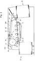
- the printing machine shown in FIG. 1 contains a feeder 1, a delivery arm 2, a conveyor belt 3, which runs around a feed-side roller 4 and a delivery-side roller 5, is held tensioned by these and is driven in the direction indicated by an arrow, and five digital printing units 6, which are arranged one behind the other along the run of the conveyor belt 3 running from the feeder 1 to the delivery 2.
- a suction roller 11 and a deflection roller 12 which can be pivoted in the direction of the roller 5 are mounted.
- a boom conveyor belt 13 runs between the suction roller 11 and the deflection roller 12 on the one hand and the roller 5 on the other hand and runs over a stack 14 of the boom 2.
- a further suction roller 18 and a transfer belt 19 are arranged, which is connected to an inclined turning pocket 20.
- the lower end of the turning pocket 20 points in the direction of the conveyor rollers 10.
- the sheets on the feeder 1 are individually picked up by the sucker 7 and placed between the feeder rollers 8.
- the feed rollers 8 accelerate the sheets in the direction of the conveyor rollers 10, double sheets being recognized by a sensor (not shown) and being ejected into the double sheet pocket 9.
- the separated sheets are conveyed by the conveyor rollers 10 onto the conveyor belt 3, whereby they are sucked on or by electrostatic forces on the surface of the Conveyor belt 3 are held.
- the conveyor belt 3 transports the sheets along the printing units 6 to the delivery unit 2.
- the suction roller 11 is activated, which contacts the conveyor belt 3 on the roller 5 on the delivery side, so that the sheets are directed onto the delivery conveyor belt 13 and are conveyed therefrom onto the delivery stack 14.
- the printing units 6 and the conveyor belt 3 are operated at a speed which corresponds to twice the cycle of the feeder 1.
- the sheets fed by the feeder 1 are printed on one side in a first pass through the printing units 6, and the sheets printed on one side are held on the conveyor belt 3 by pressing the deflection roller 12 against the roller 5.
- the conveyor belt 3 transports the sheets printed on one side back on its upper run in the direction of the delivery arm 2 and puts them in the reversible pocket 20, from which they return to the conveyor belt 3 in the opposite orientation via the conveyor rollers 10.
- the sheets printed on one side are fed into the spaces between the new sheets from the feeder 1, which arise from the operation of the feeder 1 with a cycle that corresponds to half the speed of the conveyor belt 3.
- it is possible to feed 20 individual sheets into the ongoing printing process e.g. B. Book cover.
- the sheets printed on one side are printed on the other side in the second pass by the correspondingly controlled digital printing units 6, which allow a new print image for each sheet, and the sheets printed on both sides are guided by the suction roller 11 into the delivery 2, while the intervening arches by the Printing units 6 have been printed on the first page, are held on the conveyor belt 3 by the deflecting roller 12.
- the suction roller 11 and the deflection roller 12 are operated alternately in this beautiful and reverse printing operation and form a mutually controlled arc switch.
- the suction roller 11 or the deflection roller 12 and the suction roller 16 or the deflection roller 17 in front of the sample sheet pocket 15, which form a further sheet switch, are also controlled so that a sample sheet with the desired Print page is ejected up into the sample sheet pocket 15.
- the sample sheet pocket 15 is open at the top, so that the sheets can be both easily removed and inspected by the printer without having to remove them from the sample sheet pocket 15.
- the printing press described above can be switched from perfecting to reverse printing, the same printing units as in straight printing being used in reverse printing operation. Only as many printing units are required as the maximum number of colors required for a page.
- the total length of the printing press which is essentially determined by the printing units arranged in series along a flat transport means, is therefore minimal.
- FIG. 2 shows a printing press with a separate, removable return transport device.
- Fig. 2 shows a printing press with a feeder 21, a delivery 22 and a conveyor belt 23, which runs around a feed-side roller 24 and a delivery-side roller 25, is held taut by these and in the is driven by an arrow indicated by it, and four digital printing units 26 which are arranged one behind the other along the run of the conveyor belt 23 from the feeder 21 to the delivery arm 22.
- This arrangement differs from the arrangement shown in FIG. 1 essentially in that the returning run of the conveyor belt 23 is not above, but below the printing units 26.
- the printing machine of FIG. 2 has a suction device 27 and rollers 28 on the feeder 22 and a lower sheet switch 29 connected to the conveyor belt 23 on the delivery side, which is used for the sheet switch of FIG 1 corresponds functionally, but is not shown in detail.
- the counterpressure unit 30 contains a deflection drum 31, which is arranged in the vicinity of the boom 22, and a plurality of deflection rollers 32, which are arranged such that a return conveyor belt 33 with two counter-pressure belts, which is guided around the deflection drum 31 and over the deflection rollers 32 and is tensioned thereby 33A and 33B both the delivery side of the conveyor belt 23 and the area of the feeder 21 pass when it is driven, for example by the fact that the deflection drum 32 is driven.
- the counterpressure unit 30 contains, on an upper run of the return conveyor belt 33, an upper sheet switch 35 which can be controlled to direct sheets from the return conveyor belt 33 onto a sample sheet holder 36.
- the counterpressure unit 30 opens into a turning pocket 34 which is arranged on the printing press that sheets transported in the direction of the arrow on the return conveyor belt 33 are placed in the reversible pocket 34 and can reach the conveyor belt 23 again from the reversible pocket 34.
- the sheets are transported from the feeder 21 through the conveyor belt 23 to the delivery 22 and printed by the printing units 26 in straight printing.
- the sheets printed in face-to-face printing are directed through the lower sheet switch 29 into the counter-printing unit 30, transported back there and turned over and, just like in the printing press of FIG. 1, passed back onto the conveyor belt 23, which runs at a speed which is twice the stroke of the Corresponds to feeder 21, and printed in reverse printing in the second pass through the printing units 26 and then output from the sheet switch 29 to the delivery arm 22.
- a sample sheet is output in the same manner as in the printing machine of FIG. 1 by appropriately driving the upper sheet switch 35 or the lower sheet switch 29.
- the counterpressure unit 30 can be removed together with the sheet switch 29 from the printing machine of FIG. 2.
- the printing press shown in FIG. 3 is the same printing press as that of FIG. 2, but without the counter-printing unit 30, and in this configuration is suitable for face printing, with the possibility of feeding single sheets via the reversible pocket 34.
- a modular design is thus created , Digital printing machine which can be upgraded from face printing to face and back printing with a construction which is just as compact as the printing machine from FIG. 1.
- the printing machine of Fig. 3 is also very good for processing very thick or rigid materials such as e.g. B. glass, foils, cardboard, sheet metal, etc., because the sheets are moved because of the arrangement of feeder 21, boom 22 and the intermediate printing units 26 on a straight path, so that no sheet deformation takes place.
- This path is inclined slightly downwards for ergometric reasons, but can also be horizontal.
- FIG. 4 A further development of the printing machine of FIG. 3, which allows simultaneous perfecting and reverse printing operation without sheet deformation and which nevertheless has only a small overall length, is shown schematically in FIG. 4.
- a conveyor belt 40 runs around a first roller 41 and a second roller 42 arranged at a distance therefrom and is thereby held tensioned and driven.
- the first roller 41 has a smaller diameter than the second roller 42, and the axes of the rollers 41 and 42 lie in the same horizontal plane.
- Four upper printing units 43 are arranged in a row along the upper run of the conveyor belt 40 between the rollers 41 and 42, and four lower printing units 44 are arranged in a row one behind the other along the lower run of the conveyor belt 40 between the rollers 41 and 42.
- a suction roller 45 draws sheets from the bottom of a feeder stack 46 and conveys them above the second roller 42 onto the conveyor belt 40, on which they are z. B. be held by suction from the inside.
- the sheets detach from the first roller 41 due to the curvature of the first roller 41 or because no suction is produced on the circumference of the first roller 41 and arrive in a straight line in a turning pocket 47 which is on the opposite side Side of the feeder stack 46 is arranged in the extension of the upper and lower runs of the conveyor belt 40.
- the sheets are conveyed by conveyor rollers 48 onto the lower run of the conveyor belt 40, which they are straight on promotes a boom stack 49, which is seen from the turning pocket 47 behind the second roller 42 or below the feeder stack 46.
- the feeder stack 46 and the delivery stack 49 are inclined in accordance with the respectively adjacent strand of the conveyor belt 40, so that no sheet deformation takes place during the transfer.
- the boom stack 49 can also be arranged horizontally, as shown in dashed lines in FIG. 4.
- the printing units 43, 44 each print on the outside of the sheets passing on the conveyor belt 40, so that a four-color face printing takes place on the upper printing units 43 and a four-color reverse printing takes place on the lower printing units 44, without the sheets being deformed. Nevertheless, the machine arrangement shown has a short overall length, since the two rows of printing units 43, 44 lie one above the other.
- the printing machine shown schematically in FIG. 5 differs from the printing machine of FIG. 4 in that rollers 51 and 52, around which a conveyor belt 50 is guided, have the same diameter and that a further delivery arm is instead located at the location of the turning pocket 47, on which a stack 53 is formed.
- the sheets are deposited on the stack 53, while in the perfecting mode they are only temporarily stored on the stack 53 and are drawn off on the underside of the stack by a suction roller 54 and are returned to the conveyor belt 50 via conveyor rollers 55.
- a feeder stack 56, upper printing units 57, lower printing units 58 or a delivery stack 59, on which the finished printed products are placed in perfecting, are essentially in the same way as the feeder stack 46, the upper and lower printing units 43, 44 and the boom stack 49 of FIG. 4.
- upper printing units 60 for face printing, lower printing units 61 for reverse printing, a stack of feeders 62, a stack 63 for delivery in front printing and a delivery stack 64 for front and back printing are essentially the same as that corresponding elements in Fig. 5 arranged.
- FIG. 6 there is not a conveyor belt 50, but two separate conveyor belts are provided, an upper conveyor belt 65 for the sheet transport from the feeder stack 62 to the stack 63 and a lower transport belt 66 for the sheet transport from the stack 63 to the delivery stack 64 , each conveyor belt 65 and 66 running around two rollers 67.
- the upper conveyor belt 65 and the lower conveyor belt 66 run parallel and at a distance from one another, and the lower conveyor belt 66 is vertically adjustable together with the printing units 61 arranged along it and the delivery arm on which the stack 63 is formed.
- the feeder stack 62 can then be renewed without stopping the operation of the lower printing units 61 by moving the stack 63, the lower conveyor belt 66 and the lower printing units 61 in height in accordance with the reduction in the size of the stack 63, or the delivery stack 64 can be removed without stopping the upper printing units by moving these elements in accordance with the enlargement of the stack 63.
- the stack 63 can be moved in height independently of the lower conveyor belt 66. If the top of the stack 63 is brought to the same height as the transport plane of the lower conveyor belt 66, the sheets stacked for the back printing can be taken from the top instead of from the bottom of the Stack 63 are removed. The same is possible in the previously described embodiment of FIG. 5.
- FIGS. 3 to 6 in all the cases shown the side of the stack of feeders or of the delivery stack from which the sheets are removed or onto which they are delivered by the conveyor belt and, if appropriate, the input and output points of the turning device 47 are aligned or the sides of the stacks 53, 62 for intermediate storage with the associated transport level of the conveyor belts. Therefore, the entire transport path between two stacks is straight and the sheets are not deformed at any point in the transport path.
- the embodiments of FIGS. 3 to 6 are therefore outstandingly suitable for printing on materials which cannot or should not be deformed, such as sheet metal, glass, etc.
- the term "sheet” naturally does not only include paper sheets but also substrates understand other printable materials.
- the embodiments of FIGS. 4 to 6 also enable such substrates to be printed on both sides without removal.
- FIG. 7 schematically shows a printing press in which four upper printing units 70 for face printing, a stack of feeders 71, a stack 72 for delivery in face printing and a delivery stack 73 for face and back printing in principle in the same way as the corresponding elements in FIG. 6 are arranged.
- An upper conveyor belt 74 leads past the upper printing units 70 and is guided around two rollers 75 of relatively large diameter. Between Rollers 75 are two deflection rollers 76 with a small diameter, which hold the lower run of the upper conveyor belt 74 in parallel and at a substantially smaller distance from the upper run of the conveyor belt 74 than the diameter of the rollers 75.
- the impression unit 77 comprises a lower conveyor belt 78 and four lower printing units 79 arranged in a row for an impression.
- the lower conveyor belt 78 touches the upper conveyor belt 74 at one point on the circumference of the rollers 75.
- a switch, not shown, at one end of the upper conveyor belt 74 in the vicinity of the stack 72 guides the sheets transported on the upper conveyor belt 74 to the stack 72 in straight printing mode, while it allows the sheets to adhere to the upper conveyor belt 74 in the perfecting mode, from which they are transferred after the deflection around the one roller 75 at the point of contact with the lower conveyor belt 78 to the lower conveyor belt 78, which transports them past the lower printing units 79 in the direction of the delivery stack 73, as indicated by arrows.
- FIGS. 8 and 9 are also suitable for constructing a compact printing press for perfecting from printing units which have transfer cylinders or printing cylinders.
- the printing press shown schematically in FIG. 8 has eight printing units with four upper and four lower printing cylinders 80, 81 and four upper and four lower transfer cylinders 82, 83.
- the upper transfer cylinders 82 and the lower transfer cylinders 83 are each arranged one behind the other in a horizontal row at a distance which is smaller than the cylinder diameter, and the two rows lie one above the other, being horizontally offset from one another by half the center distance of the cylinders, and wherein the Transfer cylinders 82 and 83 from one row touch the transfer cylinders 83 and 82 from the other row.
- the eight transfer cylinders 82, 83 form a zigzag-shaped row, in each of which an upper transfer cylinder 82 touches a lower transfer cylinder 83 following in the row and vice versa.
- the upper impression cylinders 80 are arranged above the upper transfer cylinders 82, and the lower impression cylinders 81 are arranged below the lower transfer cylinders 83.
- a serpentine sheet transport path is formed from a feeder stack 84 to a delivery stack 85, as indicated by arrows.
- Sheets from the feeder stack 85 are guided by conveyor rollers 86 between the feeder-side upper transfer cylinder 82 and the feeder-side lower transfer cylinder 83 subsequently transported along the sheet transport path by the frictional engagement between the contacting transfer cylinders 82, 83 and then transported onto the delivery stack 85 via conveyor rollers 87.
- the perfecting takes place in one pass between the transfer rollers 82, 83, with an upper transfer roller 82 forming a counter-pressure cylinder for an adjacent lower transfer roller 83 and vice versa, and without the printing units being required for transport along special sheet transport means.
- the zigzag arrangement of the printing units results in a very short overall length.
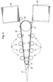
- the printing press shown schematically in FIG. 9 has two impression cylinders 90, 91 with a relatively large diameter, which are arranged one behind the other axially parallel between a feeder stack 92 and a delivery stack 93.
- On the circumference of the counter-pressure cylinder 90 on the feeder side four printing units 94 are arranged one behind the other for a straight printing, and on the circumference of the counter-pressure cylinder 91 on the boom side, four printing units 95 are arranged one behind the other for counter-printing.
- FIG. 9 only transfer cylinders of the printing units 94, 95 are shown, the transfer cylinders having a significantly smaller diameter than the impression cylinders 90, 91.
- the transfer rollers 96, 97, 98 and 99 each touch one of the impression cylinders 90, 91.
- the conveyed sheets are held by grippers, by suction or by electrostatic forces on the surfaces of the transfer rollers 96 to 99 and the impression cylinders 90 and 91 and with suitable dimensions transfer these forces at the points of contact.
- the transfer rollers 98 and 99 between the impression cylinders 90 and 91 can be replaced by any other means for transporting the sheets from the impression cylinder 90 to the impression cylinder 91, or the two impression cylinders 90 and 91 can be arranged in contact with one another, the sheets being transferred at the point of contact .
- the sheets from the feeder stack 92 between the impression cylinders 90, 91 and the respective printing units 94, 95 and transfer rollers 96 to 99 are essentially S- conveyed in a shape around the two counter-pressure cylinders 90, 91 to the boom stack 93, if one disregards the special transport route of the transfer between the two counter-pressure cylinders 90, 91.
- the essentially S-shaped sheet transport path along which the printing units 94 and 95 are arranged one behind the other enables a short overall length of the printing machine shown in FIG. 9.
- Digital printing units are particularly suitable for the printing presses shown in FIGS. 8 and 9, and their structure is also compact enough for these arrangements.
Landscapes
- Delivering By Means Of Belts And Rollers (AREA)
- Separation, Sorting, Adjustment, Or Bending Of Sheets To Be Conveyed (AREA)
- Supply, Installation And Extraction Of Printed Sheets Or Plates (AREA)
- Conveyance By Endless Belt Conveyors (AREA)
Applications Claiming Priority (2)
| Application Number | Priority Date | Filing Date | Title |
|---|---|---|---|
| DE19527266 | 1995-07-26 | ||
| DE19527266A DE19527266C2 (de) | 1995-07-26 | 1995-07-26 | Bogendruckmaschine |
Publications (3)
| Publication Number | Publication Date |
|---|---|
| EP0755784A2 true EP0755784A2 (fr) | 1997-01-29 |
| EP0755784A3 EP0755784A3 (fr) | 1997-06-25 |
| EP0755784B1 EP0755784B1 (fr) | 2003-05-28 |
Family
ID=7767815
Family Applications (1)
| Application Number | Title | Priority Date | Filing Date |
|---|---|---|---|
| EP96111893A Expired - Lifetime EP0755784B1 (fr) | 1995-07-26 | 1996-07-24 | Machine d'impression de feuilles |
Country Status (6)
| Country | Link |
|---|---|
| US (1) | US5778783A (fr) |
| EP (1) | EP0755784B1 (fr) |
| JP (1) | JPH0939203A (fr) |
| CN (1) | CN1150089A (fr) |
| AU (1) | AU715176B2 (fr) |
| DE (2) | DE19527266C2 (fr) |
Cited By (1)
| Publication number | Priority date | Publication date | Assignee | Title |
|---|---|---|---|---|
| DE102006043258B4 (de) * | 2006-09-11 | 2012-04-05 | Eastman Kodak Co. | Vorrichtung zum Wenden von Bögen |
Families Citing this family (9)
| Publication number | Priority date | Publication date | Assignee | Title |
|---|---|---|---|---|
| DE19921271A1 (de) * | 1998-06-03 | 1999-12-09 | Heidelberger Druckmasch Ag | Verfahren zum Fördern von Bogen in einer Druckmaschine sowie eine Vorrichtung zur Durchführung des Verfahrens |
| CN100434271C (zh) * | 2001-07-23 | 2008-11-19 | 三菱重工业株式会社 | 单张纸传送印刷机 |
| DE10222543B4 (de) * | 2002-05-17 | 2007-08-02 | Man Roland Druckmaschinen Ag | Auslegevorrichtung an einer Bogenverarbeitungsmaschine |
| US20040222584A1 (en) * | 2003-05-08 | 2004-11-11 | Maschinenbau Oppenweiler Binder Gmbh & Co. Kg | Process and apparatus for producing multi-leaf printed products |
| DE10356810A1 (de) * | 2003-12-05 | 2005-07-07 | Nexpress Solutions Llc | Verfahren zum Zuführen von Bögen in einer Druckmaschine |
| US7540484B2 (en) * | 2005-02-02 | 2009-06-02 | Xerox Corporation | System of opposing alternate higher speed sheet feeding from the same sheet stack |
| US7934718B2 (en) * | 2005-03-24 | 2011-05-03 | Xerox Corporation | Sheet feeding of faster rate printing systems with plural slower rate sheet feeders |
| DE102006009484B4 (de) * | 2006-02-27 | 2010-03-18 | Eastman Kodak Company | Druckmaschine für einen Bogendruck |
| DE102012017436A1 (de) * | 2012-09-04 | 2014-03-06 | Heidelberger Druckmaschinen Ag | Douplex-Druckmaschine in Reihenbauweise |
Family Cites Families (24)
| Publication number | Priority date | Publication date | Assignee | Title |
|---|---|---|---|---|
| DE234969C (fr) * | ||||
| US2625101A (en) * | 1951-06-01 | 1953-01-13 | Addressograph Multigraph | Sheet reversing mechanism for rotary perfecting sheet printing apparatus |
| DE933927C (de) * | 1951-12-04 | 1955-10-06 | Henry Cornelius Moog Fa | Bogendruckmaschine mit Auslegerkette |
| US3646325A (en) * | 1969-11-21 | 1972-02-29 | Westinghouse Learning Corp | Document reader for reading data on both sides of a document |
| US4186662A (en) * | 1977-08-22 | 1980-02-05 | A. B. Dick Company | Duplexing copying system |
| US4250806A (en) * | 1978-11-27 | 1981-02-17 | The Perkin-Elmer Corporation | Computer controlled inspector/printer document inspection |
| DE3203879C2 (de) * | 1982-02-05 | 1984-10-31 | M.A.N.- Roland Druckmaschinen AG, 6050 Offenbach | Bogen-Offset-Rotationsdruckmaschine |
| US4512255A (en) * | 1983-03-04 | 1985-04-23 | Am International | Sheet handling mechanism for duplicating machine with duplexing capability |
| FR2585287B1 (fr) * | 1985-07-26 | 1988-07-08 | Martin Sa | Machine pour le traitement de feuilles de carton defilant successivement notamment machine d'impression |
| US4717270A (en) * | 1986-02-28 | 1988-01-05 | Kabushiki Kaisha Toshiba | Paper circulating assembly for field sequential multi-color printing apparatus |
| US5001500A (en) * | 1986-12-16 | 1991-03-19 | L & C Family Partnership | Endless belt printing apparatus |
| US4814798A (en) * | 1987-06-09 | 1989-03-21 | Kentek Information Systems, Inc. | Combined electrographic printer, copier, and telefax machine with duplex capability |
| DD269356A1 (de) * | 1988-02-04 | 1989-06-28 | Polygraph Leipzig | Bildtransportdruckmaschine |
| DE8901222U1 (de) * | 1989-02-03 | 1989-03-23 | Heidelberger Druckmaschinen Ag, 6900 Heidelberg | Bogen-Rotationsdruckmaschine für einseitigen Mehrfarbendruck |
| US5195738A (en) * | 1989-06-30 | 1993-03-23 | National Computer Systems, Inc. | Single sheet picking and transport mechanism |
| DE4036253C1 (fr) * | 1990-11-14 | 1992-10-15 | Heidelberger Druckmaschinen Ag, 6900 Heidelberg, De | |
| US5343234A (en) * | 1991-11-15 | 1994-08-30 | Kuehnle Manfred R | Digital color proofing system and method for offset and gravure printing |
| DE4219116C2 (de) * | 1992-06-12 | 1995-09-28 | Roland Man Druckmasch | Bogenrotationsdruckmaschine für Mehrfarbendruck |
| DE4303797C2 (de) * | 1993-02-10 | 2001-09-20 | Heidelberger Druckmasch Ag | Rotationsdruckmaschine zum Bedrucken von Bogen |
| DE4303796C2 (de) * | 1993-02-10 | 1996-03-28 | Heidelberger Druckmasch Ag | Rotationsdruckmaschine zum beidseitigen Bedrucken von Bogen |
| JP3074105B2 (ja) * | 1993-05-13 | 2000-08-07 | 株式会社桜井グラフィックシステムズ | 枚葉印刷機の枚葉紙反転機構 |
| US5499093A (en) * | 1993-06-18 | 1996-03-12 | Xeikon Nv | Electrostatographic single-pass multiple station printer with register control |
| US5526107A (en) * | 1994-07-13 | 1996-06-11 | Scitex Corporation Ltd. | Color printing apparatus for producing duplex copies |
| US5608639A (en) * | 1995-01-13 | 1997-03-04 | Wallace Computer Services, Inc. | System and method for printing, assembly and verifying a multiple-part printed product |
-
1995
- 1995-07-26 DE DE19527266A patent/DE19527266C2/de not_active Expired - Fee Related
-
1996
- 1996-07-24 DE DE59610471T patent/DE59610471D1/de not_active Expired - Lifetime
- 1996-07-24 EP EP96111893A patent/EP0755784B1/fr not_active Expired - Lifetime
- 1996-07-25 JP JP8196556A patent/JPH0939203A/ja active Pending
- 1996-07-25 AU AU60696/96A patent/AU715176B2/en not_active Ceased
- 1996-07-26 CN CN96109217A patent/CN1150089A/zh active Pending
- 1996-07-26 US US08/686,817 patent/US5778783A/en not_active Expired - Lifetime
Cited By (1)
| Publication number | Priority date | Publication date | Assignee | Title |
|---|---|---|---|---|
| DE102006043258B4 (de) * | 2006-09-11 | 2012-04-05 | Eastman Kodak Co. | Vorrichtung zum Wenden von Bögen |
Also Published As
| Publication number | Publication date |
|---|---|
| JPH0939203A (ja) | 1997-02-10 |
| AU715176B2 (en) | 2000-01-20 |
| EP0755784B1 (fr) | 2003-05-28 |
| CN1150089A (zh) | 1997-05-21 |
| EP0755784A3 (fr) | 1997-06-25 |
| DE19527266A1 (de) | 1997-01-30 |
| DE19527266C2 (de) | 1999-04-08 |
| US5778783A (en) | 1998-07-14 |
| DE59610471D1 (de) | 2003-07-03 |
| AU6069696A (en) | 1997-01-30 |
Similar Documents
| Publication | Publication Date | Title |
|---|---|---|
| EP0755783B1 (fr) | Machine d'impression avec guidage rectiligne d'un substrat et dispositifs de retournement | |
| DE69004442T2 (de) | Gerät zum Zuführen von Papptafeln oder Blättern aus einem Stapel. | |
| DE2426217C3 (de) | Vorrichtung zum Transport von einen Querschneider verlassenden einzelnen Bogen | |
| DE19819490C1 (de) | Ausleger für eine Bogenrotationsdruckmaschine | |
| DE3612067C2 (fr) | ||
| EP0755784A2 (fr) | Machine d'impression de feuilles | |
| EP0656309A1 (fr) | Dispositif pour constituer des colis de papiers-valeur à partir de liasses de papiers valeur | |
| DE2058606A1 (de) | Verfahren und Vorrichtung zum seitlichen Ausrichten von Blaettern,insbesondere bei einer Druckpresse | |
| DE19503619A1 (de) | Koppelbare Satelliltendruckwerke | |
| EP2165954B1 (fr) | Machine de traitement de feuilles et procédé de dépôt de feuilles | |
| DE19543382C2 (de) | Verfahren zum Vereinzeln von Bogen und Anleger für eine Bogendruckmaschine zur Durchführung des Verfahrens | |
| CH690434A5 (de) | Verfahren und Vorrichtung zum Zusammenbringen von Druckereierzeugnissen. | |
| DE2452050C2 (de) | Vorrichtung zum passergerechten Anlegen von Bogen in Bogenrotationsdruckmaschinen | |
| EP3851281B1 (fr) | Dispositif de manipulation de plaques d'impression sur une machine d'impression | |
| EP0511528B1 (fr) | Dispositif pour décharger une machine d'impression de feuilles | |
| EP1507727A1 (fr) | Dispositif de sortie de feuilles pour une machine de traitement de feuilles | |
| EP1509398B1 (fr) | Dispositif de reception d'une machine rotative a feuilles | |
| DE19508254A1 (de) | Verfahren zum Transportieren/Bearbeiten von einzelnen flächigen Substraten | |
| DE69910135T3 (de) | Bogenaufnahmeeinrichtung in einer Bogenrotationsdruckmaschine | |
| DE102014220270B4 (de) | Verfahren zur Erzeugung und Ausgabe von kleinen Stapeln aus einer Bogenrotationsdruckmaschine | |
| DE102016109947A1 (de) | Auslegevorrichtung an einer Bogenrotationsdruckmaschine | |
| DE10159933B4 (de) | Papierentladevorrichtung für eine Zylinder-Siebdruckmaschine | |
| DE1957780C3 (de) | Stapelvorrichtung, insbesondere für Kopiermaschinen, zur Lagerung von Bogen | |
| DE29521986U1 (de) | Bogendruckmaschine | |
| WO2003016188A2 (fr) | Dispositif et procede d'alignement de feuilles empilees |
Legal Events
| Date | Code | Title | Description |
|---|---|---|---|
| PUAI | Public reference made under article 153(3) epc to a published international application that has entered the european phase |
Free format text: ORIGINAL CODE: 0009012 |
|
| 17P | Request for examination filed |
Effective date: 19960724 |
|
| AK | Designated contracting states |
Kind code of ref document: A2 Designated state(s): DE ES FR GB NL |
|
| PUAL | Search report despatched |
Free format text: ORIGINAL CODE: 0009013 |
|
| AK | Designated contracting states |
Kind code of ref document: A3 Designated state(s): DE ES FR GB NL |
|
| 17Q | First examination report despatched |
Effective date: 19981019 |
|
| RAP1 | Party data changed (applicant data changed or rights of an application transferred) |
Owner name: RODI, ANTON Owner name: HEIDELBERGER DRUCKMASCHINEN AKTIENGESELLSCHAFT |
|
| RAP1 | Party data changed (applicant data changed or rights of an application transferred) |
Owner name: RODI, ANTON |
|
| GRAG | Despatch of communication of intention to grant |
Free format text: ORIGINAL CODE: EPIDOS AGRA |
|
| RAP1 | Party data changed (applicant data changed or rights of an application transferred) |
Owner name: RODI, ANTON |
|
| GRAG | Despatch of communication of intention to grant |
Free format text: ORIGINAL CODE: EPIDOS AGRA |
|
| GRAG | Despatch of communication of intention to grant |
Free format text: ORIGINAL CODE: EPIDOS AGRA |
|
| GRAH | Despatch of communication of intention to grant a patent |
Free format text: ORIGINAL CODE: EPIDOS IGRA |
|
| GRAH | Despatch of communication of intention to grant a patent |
Free format text: ORIGINAL CODE: EPIDOS IGRA |
|
| GRAA | (expected) grant |
Free format text: ORIGINAL CODE: 0009210 |
|
| AK | Designated contracting states |
Designated state(s): DE ES FR GB NL |
|
| PG25 | Lapsed in a contracting state [announced via postgrant information from national office to epo] |
Ref country code: NL Free format text: LAPSE BECAUSE OF FAILURE TO SUBMIT A TRANSLATION OF THE DESCRIPTION OR TO PAY THE FEE WITHIN THE PRESCRIBED TIME-LIMIT Effective date: 20030528 Ref country code: FR Free format text: LAPSE BECAUSE OF NON-PAYMENT OF DUE FEES Effective date: 20030528 |
|
| REG | Reference to a national code |
Ref country code: GB Ref legal event code: FG4D Free format text: NOT ENGLISH |
|
| REF | Corresponds to: |
Ref document number: 59610471 Country of ref document: DE Date of ref document: 20030703 Kind code of ref document: P |
|
| PG25 | Lapsed in a contracting state [announced via postgrant information from national office to epo] |
Ref country code: ES Free format text: LAPSE BECAUSE OF FAILURE TO SUBMIT A TRANSLATION OF THE DESCRIPTION OR TO PAY THE FEE WITHIN THE PRESCRIBED TIME-LIMIT Effective date: 20030908 |
|
| GBT | Gb: translation of ep patent filed (gb section 77(6)(a)/1977) | ||
| NLV1 | Nl: lapsed or annulled due to failure to fulfill the requirements of art. 29p and 29m of the patents act | ||
| PLBE | No opposition filed within time limit |
Free format text: ORIGINAL CODE: 0009261 |
|
| STAA | Information on the status of an ep patent application or granted ep patent |
Free format text: STATUS: NO OPPOSITION FILED WITHIN TIME LIMIT |
|
| 26N | No opposition filed |
Effective date: 20040302 |
|
| EN | Fr: translation not filed | ||
| PGFP | Annual fee paid to national office [announced via postgrant information from national office to epo] |
Ref country code: DE Payment date: 20100731 Year of fee payment: 15 |
|
| PGFP | Annual fee paid to national office [announced via postgrant information from national office to epo] |
Ref country code: GB Payment date: 20100802 Year of fee payment: 15 |
|
| GBPC | Gb: european patent ceased through non-payment of renewal fee |
Effective date: 20110724 |
|
| PG25 | Lapsed in a contracting state [announced via postgrant information from national office to epo] |
Ref country code: DE Free format text: LAPSE BECAUSE OF NON-PAYMENT OF DUE FEES Effective date: 20120201 |
|
| REG | Reference to a national code |
Ref country code: DE Ref legal event code: R119 Ref document number: 59610471 Country of ref document: DE Effective date: 20120201 |
|
| PG25 | Lapsed in a contracting state [announced via postgrant information from national office to epo] |
Ref country code: GB Free format text: LAPSE BECAUSE OF NON-PAYMENT OF DUE FEES Effective date: 20110724 |