EP0754909B1 - Brennerkopf insbesondere für Gasbrenner - Google Patents
Brennerkopf insbesondere für Gasbrenner Download PDFInfo
- Publication number
- EP0754909B1 EP0754909B1 EP95830315A EP95830315A EP0754909B1 EP 0754909 B1 EP0754909 B1 EP 0754909B1 EP 95830315 A EP95830315 A EP 95830315A EP 95830315 A EP95830315 A EP 95830315A EP 0754909 B1 EP0754909 B1 EP 0754909B1
- Authority
- EP
- European Patent Office
- Prior art keywords
- combustion head
- head according
- balls
- holding body
- combustion
- Prior art date
- Legal status (The legal status is an assumption and is not a legal conclusion. Google has not performed a legal analysis and makes no representation as to the accuracy of the status listed.)
- Expired - Lifetime
Links
Images
Classifications
-
- F—MECHANICAL ENGINEERING; LIGHTING; HEATING; WEAPONS; BLASTING
- F23—COMBUSTION APPARATUS; COMBUSTION PROCESSES
- F23D—BURNERS
- F23D14/00—Burners for combustion of a gas, e.g. of a gas stored under pressure as a liquid
- F23D14/46—Details, e.g. noise reduction means
-
- F—MECHANICAL ENGINEERING; LIGHTING; HEATING; WEAPONS; BLASTING
- F23—COMBUSTION APPARATUS; COMBUSTION PROCESSES
- F23D—BURNERS
- F23D14/00—Burners for combustion of a gas, e.g. of a gas stored under pressure as a liquid
- F23D14/02—Premix gas burners, i.e. in which gaseous fuel is mixed with combustion air upstream of the combustion zone
Definitions
- the present invention relates to a combustion head, in particular for gas burners comprising the features set forth in the preamble of claim 1.
- a combustion head of this kind is disclosed in CH 452 464.
- the combustion head in question is conceived in particular for employment in small boilers and similar heating apparatuses for home use.
- the innovatory concepts suggested by the present invention can be validly adopted to produce any other type of burner, be it an atmospheric or an aerated burner with forced ventilation, to be also employed in furnaces or heating systems of an industrial type.
- burners normally used in boilers, furnaces or other heating systems for domestic and/or industrial use fed with gaseous fuel essentially consist of an internally hollow mixing body generally of a box-shaped structure, provided with means for the controlled admission of a combustible gas and combustion air drawn from the surrounding atmosphere.
- a combustion head Associated with the upper part of the mixing body is a combustion head in which a plurality of ports is formed for delivery of the combustible gas-combustion air mixture from the inside of the mixing body.
- said delivery ports essentially consist of mere through holes having a round or shaped configuration, formed through a metal plate constituting the combustion head.
- the combustible gas-combustion air mixture is fired at the exit of said through holes, thereby forming a plurality of flames arising from the external surface of the combustion head.
- the combustion heads of the above type are adopted in many situations, they however have some drawbacks in terms of burning efficiency.
- the air-gas mixing carried out within the mixing body does not always appear sufficiently efficient to ensure an optimal and intimate mingling of the two components, which is essential for achieving a correct burning.
- burners the combustion head of which essentially consists of a wire net having meshes of an appropriate size to give the outgoing gas-air mixture such a speed that the risk of backfire towards the mixing body is avoided.
- burning gives rise to a continuous flame front substantially covering the whole eternal surface of the combustion head.
- heat resulting from combustion taking place in direct contact with the wire net causes said net to become incandescent and, as a result, to dissipate heat by radiation.
- the combustion heads of this type ensure a combustion of better quality as compared with those described beforehand, but on the other hand they have a drawback too in that the wire nets, in addition to being very expensive, exhibit a structural brittleness that in many cases makes it inconvenient to use them.
- burners the combustion head of which substantially consists of one or more plates made of a ceramic material having a honeycomb structure and obtained by moulding. These ceramic plates have a greater structural strength than the previously described wire nets, but they involve high production costs too and, in addition, have a reduced resistance to thermal shocks. Furthermore, also in burners provided with such a type of combustion head, the gas-air mixing carried out within the mixing body does not prove to be sufficient for ensuring an optimal combustion development, above all in the cases in which the air and gas flow rate values must be adjusted for achieving a flame modulation.
- Burners have been also manufactured in which the combustion head essentially consists of a porous ceramic material or a non-woven fabric formed of ceramic material fibres.
- This type of combustion head has a greater resistance to thermal shocks as compared with that of the ceramic material plates.
- porous ceramic materials and non-woven fabrics involve high production costs and above all do not allow a precise measurement of the delivery ports embodied by the hollow spaces created between the various ceramic material fibres or particles having a random orientation. Therefore very thick porous materials or non-woven fabrics need to be adopted.
- an important thickness appears to be inappropriate, due to the flow resistance induced on the outgoing mixture, for use on burners of the atmospheric type requiring air to be fed by forced ventilation.
- An important thickness also involves the installation of auxiliary air and/or gas filtering devices, in order to avoid the risk that dust or other impurities may obstruct the hollow spaces between the ceramic fibres or particles, thereby impairing the burner operation.
- the Patent document GB 2259566 discloses a burner, particularly suitable for wall-mounted boilers, comprising an air mixing body which is engaged by a box-shaped holding body receiving inside a plurality of granular elements.
- the granular elements are joined to each other in the corresponding tangency points and disposed according to a lattice made triangular meshes.
- the box-shaped holding body comprises a bottom provided with a plurality of trough apertures.
- a perimetrical edge of the bottom of the box-shaped holding body is associated on an upper perimetrical edge of the mixing body.
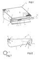
- a combustion head especially for gaseous fuel has been generally identified by reference numeral 1.
- the combustion head 1 is associated with a burner 1a which in a manner known per se comprises an internally hollow mixing body 2 into which feeding means 3 for a combustible gas-combustion air mixture opens.
- said feeding means 3 essentially comprises a feed manifold 4 along which a plurality of nozzles 5 is distributed. Through said nozzles a combustible gas coming from a pipe 4a terminating at the manifold itself is delivered in the form of a plurality of parallel and suitably spaced jets.
- the nozzles 5 are such oriented that they direct the gas jets to an inlet slot 6 formed along one side of the mixing body 2.
- a lead-in portion 7 and a spread portion 8 extend from the side edges of the inlet slot 6 and they have an extension respectively converging and diverging along the feed direction of the gas ejected from nozzles 5.
- the air feeding may also occur by forced ventilation, said forced ventilation taking the place of, or being in addition to said admission nozzle.
- the combustion head 1 located on top of the mixing body 2 so as to form a closure for same, is essentially comprised of a plurality of balls 10 of a predetermined diameter, preferably of ceramic material, physically interconnected with each other in succession at points of mutual tangency.
- the gas-air mixture admitted to the mixing body 2 will be therefore forced to pass through the combustion head 1 and will then emerge from the delivery ports 12 to be fired at the external surface 9 of said combustion head.
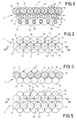
- the surfaces of balls 10 confining each delivery port 12 mutually diverge in an exponential progression along the mixture outlet direction, thereby involving an important velocity reduction in the mixture flow coming out of the delivery ports.
- burning of the mixture will take place substantially within the confined spaces between the ball surfaces diverging from the delivery ports 12, thereby giving rise to a substantially continuous flame front extending over the whole external surface 9 of the combustion head 1.
- the balls 10 belonging to each of the different superposed layers are distributed to advantage according to a symmetrically staggered positioning relative to the balls belonging to the adjoining layers.
- the mixture from the mixing body 2, while crossing the combustion head 1 is divided into a plurality of flows which are forced to follow a tortuous path of travel between the various alveoli 11 and are consequently subjected to movement in a turbulent state, which will cause a perfect homogenizing of the mixture to be fired.
- balls 10 may be replaced by granular elements of varying shapes, for example obtained by grinding a ceramic material into a given particle size and subsequently distributed in superposed layers to form said filter bed.
- the use of balls is preferred because by suitably selecting the ball diameter it is possible to establish the sizes of the alveoli 11 and delivery ports 12 in a very precise manner, depending on requirements.
- the ball diameter is provided to be included between 1 mm and 10 mm, so that the alveolus and port sizes will be big enough to enable passage of impurities possibly present in the mixture and small enough to ensure a mixture velocity capable of avoiding any risk of backfire at the delivery ports 12.
- figures 2 and 3 show a first solution in which the balls 10 provided in each layer are distributed in a geometrical lattice having triangular meshes.
- the combustion head 1 has at least three ball layers, so that none of the delivery ports 12 can directly communicate with the inside of the mixing body 2 and therefore each delivery port 12 can be reached by the mixture after the latter has passed through several alveoli 11 disposed at mutually staggered locations.
- the balls 10 of each layer are on the contrary distributed following a geometrical lattice formed of square meshes.
- the arrangement of at least two ball layers is sufficient to enable the mixture to reach the delivery ports 12 after following a tortuous path across the combustion head 1.
- internally hollow balls 10 may be provided, as shown in Fig. 6, so that a further reduction of the ball mass is achieved and therefore a reduction in the heat amount therein stored during burning.
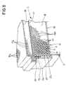
- the combustion head 1 comprises a box-shaped holding body 13 having at least one bottom 14 provided with a plurality of through apertures 14a defining a substantially reticular structure, and at least one side wall 15 extending perimetrically from said bottom 14 with which it defines a housing 16 for receiving said plurality of granular elements consisting in this case (as already said) of balls 10 of a predetermined diameter.
- the box-shaped holding body 13 is thoroughly made of a suitably shaped reticular element. It should be noted that the box-shaped holding body 13 is received in a perimetric seat 2b defined by an upper edge 2a of the mixing body so that it substantially acts as a closure for the mixing body. Associated with the holding body 13 is a closing element 17 disposed on the opposite side from the bottom wall 14 and also provided with a plurality of through apertures 17a defining a substantially reticular structure. The closing element 17 too is made of a reticular element which is suitably shaped so that its shape matches that of the side wall 15 of the holding body 13.
- the granular elements or balls 10 can be disposed within the housing 16 without a mutual fixing being required.
- an additional covering element 18 associated with the side wall 15 of the holding body 13 may be provided. It is located a given distance from the closing element 17, away from the bottom wall 14.
- This additional covering element 18 too designed to be brought to incandescence by the flame in order to dissipate heat by radiation, is provided with a plurality of through apertures 18a and can be made starting directly from a reticular element.
- annular seal 19 is interposed between the side wall 15 of the box-shaped body 13 and the upper edge 2a of the mixing body 2.
- Seal 19 is adapted to ensure an efficient tightness to the connection between the box-shaped body and the mixing body and at the same time, due to its intrinsic capability of being deformed, can compensate for the thermal expansions to which the other components of the combustion head 1 are subjected, thereby avoiding the occurrence of inner stresses capable of impairing the structural integrity of the combustion head.
- Clamping means consisting for example of an annular gripping element 20 having a C-shaped transverse section causes the final fastening between the upper edge 2a of tho mixing body 2, the side wall 15 of the holding body 13, the closing element 17 and the additional closing element 18, if present.
- the box-shaped holding body 13 is first made, for example starting from a reticular element or a plate suitably provided with through holes conveniently distributed to form a substantially netlike structure.
- said plurality of granular elements 10 may be introduced into the housing 16 so as to define the filter bed provided with intercommunicating alveoli or hollow spaces 11.
- the holding body may be submitted to advantage to a further step involving a vibrating action.
- the closing element 17 is put on top of the granular elements and associated therewith and the additional closing element 18, if any, is put close to the upper edge of the side wall 15 of the holding body 13.
- the holding body 13 can be associated with the perimetric housing 16 defined by the upper edge 2a of the mixing body 2, upon optional interposition of the annular seal 19.
- the box-shaped holding body 13, closing element 17 and additional closing element 18 are fastened to the upper edge 2a of the mixing body 2 after carrying out a folding operation of the respective perimetric edges and a subsequent operation involving clamping of the perimetric edges by the annular gripping element 20.
- the present invention achieves the intended purposes.
- the combustion head in question due to its particular structural configuration, is in fact capable of ensuring an optimal efficiency in carrying out the combustion process on the external surface 9.
- the combustion thoroughly takes place in the spaces defined by the upper surface portions of the balls at the outside of the delivery ports, which is advantageous for the combustion quality.
- an optimal control of the stoichiometric ratio in the gas-air mixture is ensured, together with the maintenance of a fire temperature adapted to avoid the formation of nitric oxides and/or other harmful products of combustion.
- the combustion quality is also improved by the intimate mixing taking place between the air and gas following passage of the mixture through the lattice of alveoli defined by the different ball layers.
- the combustion head according to the invention can be mass produced at low manufacturing costs. Actually, it is noted that hollow or solid balls made of ceramic material are easily available on the market. In addition the manufacturing cost can be further reduced if, instead of balls, granular elements of different configuration obtained by grinding of scrap material from other industrial processes are used.
- the combustion head may be made of several plate-like portions formed by said balls or granular elements of different shapes, disposed consecutively side by side and supported by a bearing framework.
- the balls may be distributed in a tubular configuration, instead of having a flat configuration as shown in the accompanying drawings.
- the balls may advantageously have a diameter increasingly growing from the inner to the outer layers in order to ensure that also the balls belonging to the outermost layers should be touching at the respective tangency points.
Claims (22)
- Brennkopf, insbesondere für Gasbrenner, umfassend einen innen hohlen Mischkörper (2) und Mittel (3) zur Zuführung einer Mischung von gasförmigen Brennmitteln/Verbrennungsluft in den Mischkörper (2), wobei der Mischkopf (1) mit Abgabeöffnungen (12) versehen ist, über welche die Mischung gasförmiger Brennstoff/Verbrennungsluft durch den Mischkörper (2) ausgestoßen und gezündet wird, eine Vielzahl von, eines nach dem anderen in Stellen gegenseitiger Berührung verbundenen kornförmigen Elementen (10), die im wesentlichen ein, ein Netz von Zwischenräumen (11) aufweisendes Filterbett festlegen, die miteinander verbunden sind und an einer Außenfläche (9) des Brennkopfes (1) eine Vielzahl von Abgabeöffnungen (12) festlegen, die gemäß der gesamten Abwicklung der Außenfläche selbst verteilt sind; ein Gehäuse (13) mit mindestens einem Boden (14), das mit einer Vielzahl von eine im wesentlichen netzförmige Struktur festlegenden Durchgangsöffnungen (14a) und mit mindestens einer Seitenwand (15) versehen ist, die sich umlaufend von dem Boden (14) erstreckt und mit diesem letzteren eine Aufnahme (16) zur Aufnahme der Vielzahl von kornförmigen Elementen (10) festlegt; mindestens ein Schließelement (17), das der Seitenwand (15) des Gehäuses (13) gegenüber der Bodenwand (14) abgewandten Seite zugeordnet ist, wobei das Schließelement (17) gleichfalls mit einer Vielzahl von Durchgangsöffnungen (17a) versehen ist, die eine im wesentlichen netzförmige Struktur festlegen;
dadurch gekennzeichnet, dass das Gehäuse (13) aus einem netzförmigen Element besteht und im Bereich eines umlaufenden Sitzes (2b) aufgenommen ist, der durch einen oberen Rand (2a) des Mischkörpers (2) festgelegt ist. - Brennkopf nach Anspruch A dadurch gekennzeichnet, dass die bodenförmigen Elemente aus Kugeln (10) vorgegebenen Durchmessers bestehen.
- Brennkopf nach Anspruch 1, dadurch gekennzeichnet, dass die kornförmigen Elemente (10) in Keramik ausgeführt sind.
- Brennkopf nach Anspruch 2, dadurch gekennzeichnet, dass die Kugeln (10) innen hohl sind.
- Brennkopf nach Anspruch 2, dadurch gekennzeichnet, dass der vorgegebene Durchmesser für jede der Kugeln (10) einen Betrag zwischen 1 mm und 10 mm besitzt.
- Brennkopf nach Anspruch 1, dadurch gekennzeichnet, dass die kornförmigen Elemente (10) miteinander durch Sinterung an den jeweiligen Berührungspunkten vereint sind.
- Brennkopf nach Anspruch 1, dadurch gekennzeichnet, dass die kornförmigen Elemente (10) miteinander durch Verkleben an den jeweiligen Berührungsstellen vereint sind.
- Brennkopf nach Anspruch 2, dadurch gekennzeichnet, dass mindestens eine Schicht von Kugeln (10) vorgesehen ist, die gemäß einem geometrischen Netz mit rechteckigen Maschen verteilt sind.
- Brennkopf nach Anspruch 2, dadurch gekennzeichnet, dass mindestens eine Kugelschicht vorgesehen ist, in der die Kugeln (10) gemäß einem geometrischen Netz mit quadratischen Maschen verteilt sind.
- Brennkopf nach Anspruch 8, dadurch gekennzeichnet, dass die Kugeln (10) längs mindestens drei zueinander aufeinander liegenden Schichten verteilt sind, wobei die jeder Schicht angehörenden Kugeln eine Positionierung aufweisen, die gegenüber den anliegenden, den benachbarten Schichten angehörenden Kugeln symmetrisch versetzt sind.
- Brennkopf nach Anspruch 9, dadurch gekennzeichnet, dass die Kugeln (10) längs mindestens zwei zueinander übereinander liegenden Schichten verteilt sind, wobei die einer jeden Schicht angehörenden Kugeln eine Positionierung aufweisen, die gegenüber den anliegenden, den benachbarten Schichten angehörenden Kugeln symmetrisch versetzt sind.
- Brennkopf nach Anspruch A dadurch gekennzeichnet, dass die kornförmigen Elemente (10) über einen gegenseitigen Kontakt in den Berührungsstellen miteinander verbunden sind.
- Brennkopf nach Anspruch A dadurch gekennzeichnet, dass das Schließelement (17) aus einem netzförmigen Element besteht.
- Brennkopf nach Anspruch 1, dadurch gekennzeichnet, dass er ein Hilfsabdeckelement (18) umfasst, das der Seitenwand (15) des Gehäuses (13) zugeordnet und mit einem vorgegebenen Abstand von diesem Schließelement (17) in Entfernung von der Bodenwand (14) angeordnet ist, wobei das Hilfsabdeckelement (18) mit einer Vielzahl von Durchgangsöffnungen (18a) versehen ist, die eine im wesentlichen netzförmige Struktur festlegen.
- Brennkopf nach Anspruch 14, dadurch gekennzeichnet, dass das Hilfsabdeckelement (18) aus einem netzförmigen Element besteht.
- Brennkopf nach Anspruch 1, dadurch gekennzeichnet, dass er eine Ringdichtung (19) umfasst, die wirksam zwischen der Seitenwand (15) des Gehäuses (13) und dem oberen Rand (2a) des Mischkörpers (2) zwischengeschaltet ist.
- Brennkopf nach Anspruch 1, dadurch gekennzeichnet, dass er überdies Spannmittel (20) zur gegenseitigen Befestigung des oberen Randes (2a) des Mischkörpers (2), der Seitenwand (15) des Gehäuses (13) und des Schließelementes (17) umfasst.
- Brennkopf nach Anspruch 17, dadurch gekennzeichnet, dass die Spannmittel ein ringförmiges Klammerelement (20) umfassen, das eine im wesentlichen "C"-förmig ausgebildeten Querschnitt aufweist.
- Verfahren zur Ausführung und den Einbau eines Brennkopfes, so wie im Anspruch 1 definiert, dadurch gekennzeichnet, dass es folgende Arbeitsschritte umfasst:wobei nach dem Anfertigungsschritt ein weiterer Arbeitsschritt vorgesehen ist, bei dem das Gehäuse (13) in einem Umfangssitz (2b) in Eingriff steht, der durch den oberen Rand (2a) des Mischkörpers (2) festgelegt ist.Anfertigung eines Gehäuses (13) mit mindestens einer Bodenwand (14), die mit einer Vielzahl von durchgehenden Öffnungen (14a), die eine im wesentlichen netzförmige Struktur festlegen, und mit mindestens einer Seitenwand (15) versehen ist, die umlaufend von der Bodenwand (14) sich erstreckt und mit diesen letzteren eine Aufnahme (16) festlegt;Einfüllung in dieser Aufnahme (16) einer Vielzahl von kornförmigen Elementen (10), um im wesentlichen ein Filterbett zu bilden, das ein Netz von Zwischenräumen (11) aufweist, die miteinander in Verbindung stehen und eine Vielzahl von Abgabeöffnungen (12) festlegen;Zuordnung oberhalb der kornförmigen Elemente (10) eines Schließelementes (17), das mit einer Vielzahl von Durchgangsöffnungen (17a) versehen ist, die eine im wesentlichen netzförmige Struktur festlegen,
- Verfahren nach Anspruch 19, dadurch gekennzeichnet, dass in Begleitung mit dem Arbeitsschritt des Einfüllens der kornförmigen Elemente (10) das Gehäuse einem Schüttelarbeitsschritt unterliegt.
- Verfahren nach Anspruch 19, dadurch gekennzeichnet, dass das Gehäuse (13) in einem umlaufenden Sitz (2b) in einer Zwischenschaltung einer Ringdichtung in Eingriff steht, die sich zwischen der Seitenwand des Gehäuses und dem oberen Rand des Mischkörpers (2) erstreckt.
- Verfahren nach Anspruch 19, dadurch gekennzeichnet, dass, nach dem Schritt der Zuordnung des Schließelementes (17) zu dem Gehäuse (13), ein weiterer Arbeitsschritt der Zuordnung vorgesehen ist, bei der das Hilfsabdeckelement (18) oberhalb mit einem vorgegebenen Abstand vom Schließelement (17) in Entfernung von der Bodenwand (14) angeordnet wird, wobei das Hilfsabdeckelement (18) mit einer Vielzahl von Durchgangsöffnungen (18a) versehen ist, die eine im wesentlichen netzartige Struktur festlegen.
Priority Applications (4)
| Application Number | Priority Date | Filing Date | Title |
|---|---|---|---|
| ES95830315T ES2143028T3 (es) | 1995-07-21 | 1995-07-21 | Cabezal de combustion, en particular para quemadores de gas. |
| EP95830315A EP0754909B1 (de) | 1995-07-21 | 1995-07-21 | Brennerkopf insbesondere für Gasbrenner |
| DE69514916T DE69514916T2 (de) | 1995-07-21 | 1995-07-21 | Brennerkopf insbesondere für Gasbrenner |
| AT95830315T ATE189512T1 (de) | 1995-07-21 | 1995-07-21 | Brennerkopf insbesondere für gasbrenner |
Applications Claiming Priority (1)
| Application Number | Priority Date | Filing Date | Title |
|---|---|---|---|
| EP95830315A EP0754909B1 (de) | 1995-07-21 | 1995-07-21 | Brennerkopf insbesondere für Gasbrenner |
Publications (2)
| Publication Number | Publication Date |
|---|---|
| EP0754909A1 EP0754909A1 (de) | 1997-01-22 |
| EP0754909B1 true EP0754909B1 (de) | 2000-02-02 |
Family
ID=8221977
Family Applications (1)
| Application Number | Title | Priority Date | Filing Date |
|---|---|---|---|
| EP95830315A Expired - Lifetime EP0754909B1 (de) | 1995-07-21 | 1995-07-21 | Brennerkopf insbesondere für Gasbrenner |
Country Status (4)
| Country | Link |
|---|---|
| EP (1) | EP0754909B1 (de) |
| AT (1) | ATE189512T1 (de) |
| DE (1) | DE69514916T2 (de) |
| ES (1) | ES2143028T3 (de) |
Families Citing this family (2)
| Publication number | Priority date | Publication date | Assignee | Title |
|---|---|---|---|---|
| DE10220155A1 (de) * | 2001-07-31 | 2003-11-13 | Rolf Kresel | Gasbrenner für Zentralheizungen |
| ES2293768B1 (es) * | 2005-04-11 | 2009-03-16 | Jose Maria Vergara Uranga | Cuerpo de caldeo polivalente. |
Family Cites Families (8)
| Publication number | Priority date | Publication date | Assignee | Title |
|---|---|---|---|---|
| US3322179A (en) * | 1963-04-09 | 1967-05-30 | Paul H Goodell | Fuel burner having porous matrix |
| GB1095998A (en) * | 1964-04-21 | 1967-12-20 | Bullfinch Gas Equip | Improvements relating to gas-burning heating appliances |
| DE2036510A1 (de) * | 1969-08-07 | 1971-02-18 | C.A.V. Ltd., Birmingham (Grossbritannien) | Brenner fur ein Brennstoff/Luftgemisch |
| GB2155613A (en) * | 1984-03-06 | 1985-09-25 | Allday & Co Ltd William | Forge hearth burner assembly |
| JPS62258917A (ja) * | 1986-04-18 | 1987-11-11 | Miura Co Ltd | セラミック粒子からなる助燃体を用いた表面燃焼バーナ |
| JPH01121609A (ja) * | 1987-11-05 | 1989-05-15 | Miura Co Ltd | 表面燃焼用バーナヘッド組立体 |
| IT1251560B (it) * | 1991-09-06 | 1995-05-17 | Nuovopignone Ind Meccaniche Ef | Bruciatore perfezionato, particolarmente adatto per caldaie murali |
| DE4136918A1 (de) * | 1991-11-11 | 1993-05-13 | Luedi Roger | Flammenhalter fuer strahlungsbrenner |
-
1995
- 1995-07-21 DE DE69514916T patent/DE69514916T2/de not_active Expired - Fee Related
- 1995-07-21 ES ES95830315T patent/ES2143028T3/es not_active Expired - Lifetime
- 1995-07-21 AT AT95830315T patent/ATE189512T1/de not_active IP Right Cessation
- 1995-07-21 EP EP95830315A patent/EP0754909B1/de not_active Expired - Lifetime
Also Published As
| Publication number | Publication date |
|---|---|
| ATE189512T1 (de) | 2000-02-15 |
| DE69514916D1 (de) | 2000-03-09 |
| ES2143028T3 (es) | 2000-05-01 |
| DE69514916T2 (de) | 2000-06-29 |
| EP0754909A1 (de) | 1997-01-22 |
Similar Documents
| Publication | Publication Date | Title |
|---|---|---|
| JP4540263B2 (ja) | 液状及びガス状燃料を燃焼する低窒素酸化物装置及び方法。 | |
| US3051464A (en) | Air-heating gas burner | |
| US4927355A (en) | Burner assembly | |
| EP0769120B1 (de) | Mischkammer für einen brenner | |
| US5375996A (en) | Combustion apparatus having heat-recirculation function | |
| US3185204A (en) | Radiant gas fired burner | |
| CA1224131A (en) | Burner | |
| US5591025A (en) | Combustion head, in particular for gas burners | |
| EP0754909B1 (de) | Brennerkopf insbesondere für Gasbrenner | |
| EP0594262A1 (de) | Gazebrenner | |
| US3723052A (en) | Liquid fuel burner apparatus | |
| JPH0820057B2 (ja) | 先混合式ガスバーナ | |
| JPS62711A (ja) | 燃焼装置 | |
| JPS5866707A (ja) | バ−ナ | |
| JP2001065821A (ja) | 炎孔部材及び炎孔部材を有する燃焼装置 | |
| US3653371A (en) | Hot air furnace having l-shaped burners | |
| JPS59112111A (ja) | 予混合式燃焼器 | |
| SU1333958A1 (ru) | Пылеугольна горелка | |
| EP0892213A1 (de) | Filterbettbrenner und damit durchgeführtes Gasverbrennungsverfahren | |
| JPH08591Y2 (ja) | ガスバーナ用保炎装置 | |
| JPS59185910A (ja) | 予混合式燃焼器 | |
| JP3012473B2 (ja) | 燃焼装置 | |
| JPH02143003A (ja) | 給湯器 | |
| JPH1030804A (ja) | 元混合式面状火炎型バーナ | |
| JPS6026210A (ja) | ガスバ−ナ |
Legal Events
| Date | Code | Title | Description |
|---|---|---|---|
| PUAI | Public reference made under article 153(3) epc to a published international application that has entered the european phase |
Free format text: ORIGINAL CODE: 0009012 |
|
| 17P | Request for examination filed |
Effective date: 19960910 |
|
| AK | Designated contracting states |
Kind code of ref document: A1 Designated state(s): AT BE CH DE DK ES FR GB GR IE IT LI LU MC NL PT SE |
|
| 17Q | First examination report despatched |
Effective date: 19980421 |
|
| GRAG | Despatch of communication of intention to grant |
Free format text: ORIGINAL CODE: EPIDOS AGRA |
|
| RAP1 | Party data changed (applicant data changed or rights of an application transferred) |
Owner name: SIABS INDUSTRY S.R.L. |
|
| RIN1 | Information on inventor provided before grant (corrected) |
Inventor name: INVERNIZZI, GIANMARIO |
|
| GRAG | Despatch of communication of intention to grant |
Free format text: ORIGINAL CODE: EPIDOS AGRA |
|
| GRAH | Despatch of communication of intention to grant a patent |
Free format text: ORIGINAL CODE: EPIDOS IGRA |
|
| GRAH | Despatch of communication of intention to grant a patent |
Free format text: ORIGINAL CODE: EPIDOS IGRA |
|
| GRAA | (expected) grant |
Free format text: ORIGINAL CODE: 0009210 |
|
| AK | Designated contracting states |
Kind code of ref document: B1 Designated state(s): AT BE CH DE DK ES FR GB GR IE IT LI LU MC NL PT SE |
|
| PG25 | Lapsed in a contracting state [announced via postgrant information from national office to epo] |
Ref country code: GR Free format text: LAPSE BECAUSE OF NON-PAYMENT OF DUE FEES Effective date: 20000202 Ref country code: AT Free format text: LAPSE BECAUSE OF FAILURE TO SUBMIT A TRANSLATION OF THE DESCRIPTION OR TO PAY THE FEE WITHIN THE PRESCRIBED TIME-LIMIT Effective date: 20000202 |
|
| REF | Corresponds to: |
Ref document number: 189512 Country of ref document: AT Date of ref document: 20000215 Kind code of ref document: T |
|
| ITF | It: translation for a ep patent filed |
Owner name: BUGNION S.P.A. |
|
| REG | Reference to a national code |
Ref country code: CH Ref legal event code: EP |
|
| REF | Corresponds to: |
Ref document number: 69514916 Country of ref document: DE Date of ref document: 20000309 |
|
| REG | Reference to a national code |
Ref country code: CH Ref legal event code: NV Representative=s name: ISLER & PEDRAZZINI AG |
|
| ET | Fr: translation filed | ||
| REG | Reference to a national code |
Ref country code: ES Ref legal event code: FG2A Ref document number: 2143028 Country of ref document: ES Kind code of ref document: T3 |
|
| PG25 | Lapsed in a contracting state [announced via postgrant information from national office to epo] |
Ref country code: SE Free format text: LAPSE BECAUSE OF FAILURE TO SUBMIT A TRANSLATION OF THE DESCRIPTION OR TO PAY THE FEE WITHIN THE PRESCRIBED TIME-LIMIT Effective date: 20000502 Ref country code: PT Free format text: LAPSE BECAUSE OF FAILURE TO SUBMIT A TRANSLATION OF THE DESCRIPTION OR TO PAY THE FEE WITHIN THE PRESCRIBED TIME-LIMIT Effective date: 20000502 Ref country code: DK Free format text: LAPSE BECAUSE OF FAILURE TO SUBMIT A TRANSLATION OF THE DESCRIPTION OR TO PAY THE FEE WITHIN THE PRESCRIBED TIME-LIMIT Effective date: 20000502 |
|
| REG | Reference to a national code |
Ref country code: IE Ref legal event code: FG4D |
|
| PG25 | Lapsed in a contracting state [announced via postgrant information from national office to epo] |
Ref country code: LU Free format text: LAPSE BECAUSE OF NON-PAYMENT OF DUE FEES Effective date: 20000721 Ref country code: IE Free format text: LAPSE BECAUSE OF NON-PAYMENT OF DUE FEES Effective date: 20000721 |
|
| PG25 | Lapsed in a contracting state [announced via postgrant information from national office to epo] |
Ref country code: MC Free format text: THE PATENT HAS BEEN ANNULLED BY A DECISION OF A NATIONAL AUTHORITY Effective date: 20000731 |
|
| PLBE | No opposition filed within time limit |
Free format text: ORIGINAL CODE: 0009261 |
|
| STAA | Information on the status of an ep patent application or granted ep patent |
Free format text: STATUS: NO OPPOSITION FILED WITHIN TIME LIMIT |
|
| 26N | No opposition filed | ||
| REG | Reference to a national code |
Ref country code: IE Ref legal event code: MM4A |
|
| PGFP | Annual fee paid to national office [announced via postgrant information from national office to epo] |
Ref country code: FR Payment date: 20010712 Year of fee payment: 7 |
|
| PGFP | Annual fee paid to national office [announced via postgrant information from national office to epo] |
Ref country code: DE Payment date: 20010716 Year of fee payment: 7 |
|
| PGFP | Annual fee paid to national office [announced via postgrant information from national office to epo] |
Ref country code: GB Payment date: 20010718 Year of fee payment: 7 |
|
| PGFP | Annual fee paid to national office [announced via postgrant information from national office to epo] |
Ref country code: NL Payment date: 20010730 Year of fee payment: 7 Ref country code: CH Payment date: 20010730 Year of fee payment: 7 |
|
| PGFP | Annual fee paid to national office [announced via postgrant information from national office to epo] |
Ref country code: ES Payment date: 20010822 Year of fee payment: 7 |
|
| PGFP | Annual fee paid to national office [announced via postgrant information from national office to epo] |
Ref country code: BE Payment date: 20010918 Year of fee payment: 7 |
|
| REG | Reference to a national code |
Ref country code: GB Ref legal event code: IF02 |
|
| PG25 | Lapsed in a contracting state [announced via postgrant information from national office to epo] |
Ref country code: GB Free format text: LAPSE BECAUSE OF NON-PAYMENT OF DUE FEES Effective date: 20020721 |
|
| PG25 | Lapsed in a contracting state [announced via postgrant information from national office to epo] |
Ref country code: ES Free format text: LAPSE BECAUSE OF NON-PAYMENT OF DUE FEES Effective date: 20020722 |
|
| PG25 | Lapsed in a contracting state [announced via postgrant information from national office to epo] |
Ref country code: LI Free format text: LAPSE BECAUSE OF NON-PAYMENT OF DUE FEES Effective date: 20020731 Ref country code: CH Free format text: LAPSE BECAUSE OF NON-PAYMENT OF DUE FEES Effective date: 20020731 Ref country code: BE Free format text: LAPSE BECAUSE OF NON-PAYMENT OF DUE FEES Effective date: 20020731 |
|
| BERE | Be: lapsed |
Owner name: *SIABS INDUSTRY S.R.L. Effective date: 20020731 |
|
| PG25 | Lapsed in a contracting state [announced via postgrant information from national office to epo] |
Ref country code: NL Free format text: LAPSE BECAUSE OF NON-PAYMENT OF DUE FEES Effective date: 20030201 Ref country code: DE Free format text: LAPSE BECAUSE OF NON-PAYMENT OF DUE FEES Effective date: 20030201 |
|
| GBPC | Gb: european patent ceased through non-payment of renewal fee |
Effective date: 20020721 |
|
| REG | Reference to a national code |
Ref country code: CH Ref legal event code: PL |
|
| PG25 | Lapsed in a contracting state [announced via postgrant information from national office to epo] |
Ref country code: FR Free format text: LAPSE BECAUSE OF NON-PAYMENT OF DUE FEES Effective date: 20030331 |
|
| NLV4 | Nl: lapsed or anulled due to non-payment of the annual fee |
Effective date: 20030201 |
|
| REG | Reference to a national code |
Ref country code: FR Ref legal event code: ST |
|
| REG | Reference to a national code |
Ref country code: ES Ref legal event code: FD2A Effective date: 20030811 |
|
| PG25 | Lapsed in a contracting state [announced via postgrant information from national office to epo] |
Ref country code: IT Free format text: LAPSE BECAUSE OF NON-PAYMENT OF DUE FEES;WARNING: LAPSES OF ITALIAN PATENTS WITH EFFECTIVE DATE BEFORE 2007 MAY HAVE OCCURRED AT ANY TIME BEFORE 2007. THE CORRECT EFFECTIVE DATE MAY BE DIFFERENT FROM THE ONE RECORDED. Effective date: 20050721 |