EP0752533B1 - Spiralverdichter - Google Patents
Spiralverdichter Download PDFInfo
- Publication number
- EP0752533B1 EP0752533B1 EP96201783A EP96201783A EP0752533B1 EP 0752533 B1 EP0752533 B1 EP 0752533B1 EP 96201783 A EP96201783 A EP 96201783A EP 96201783 A EP96201783 A EP 96201783A EP 0752533 B1 EP0752533 B1 EP 0752533B1
- Authority
- EP
- European Patent Office
- Prior art keywords
- rotor
- bearing
- spiral
- oil chamber
- compressor according
- Prior art date
- Legal status (The legal status is an assumption and is not a legal conclusion. Google has not performed a legal analysis and makes no representation as to the accuracy of the status listed.)
- Expired - Lifetime
Links
- 238000001816 cooling Methods 0.000 claims description 10
- 238000007789 sealing Methods 0.000 claims description 2
- 238000007664 blowing Methods 0.000 claims 1
- 238000005461 lubrication Methods 0.000 description 6
- 239000004519 grease Substances 0.000 description 5
- 238000005192 partition Methods 0.000 description 3
- 238000012423 maintenance Methods 0.000 description 2
Images
Classifications
-
- F—MECHANICAL ENGINEERING; LIGHTING; HEATING; WEAPONS; BLASTING
- F04—POSITIVE - DISPLACEMENT MACHINES FOR LIQUIDS; PUMPS FOR LIQUIDS OR ELASTIC FLUIDS
- F04C—ROTARY-PISTON, OR OSCILLATING-PISTON, POSITIVE-DISPLACEMENT MACHINES FOR LIQUIDS; ROTARY-PISTON, OR OSCILLATING-PISTON, POSITIVE-DISPLACEMENT PUMPS
- F04C18/00—Rotary-piston pumps specially adapted for elastic fluids
- F04C18/02—Rotary-piston pumps specially adapted for elastic fluids of arcuate-engagement type, i.e. with circular translatory movement of co-operating members, each member having the same number of teeth or tooth-equivalents
- F04C18/0207—Rotary-piston pumps specially adapted for elastic fluids of arcuate-engagement type, i.e. with circular translatory movement of co-operating members, each member having the same number of teeth or tooth-equivalents both members having co-operating elements in spiral form
- F04C18/0215—Rotary-piston pumps specially adapted for elastic fluids of arcuate-engagement type, i.e. with circular translatory movement of co-operating members, each member having the same number of teeth or tooth-equivalents both members having co-operating elements in spiral form where only one member is moving
-
- F—MECHANICAL ENGINEERING; LIGHTING; HEATING; WEAPONS; BLASTING
- F04—POSITIVE - DISPLACEMENT MACHINES FOR LIQUIDS; PUMPS FOR LIQUIDS OR ELASTIC FLUIDS
- F04C—ROTARY-PISTON, OR OSCILLATING-PISTON, POSITIVE-DISPLACEMENT MACHINES FOR LIQUIDS; ROTARY-PISTON, OR OSCILLATING-PISTON, POSITIVE-DISPLACEMENT PUMPS
- F04C29/00—Component parts, details or accessories of pumps or pumping installations, not provided for in groups F04C18/00 - F04C28/00
- F04C29/02—Lubrication; Lubricant separation
- F04C29/028—Means for improving or restricting lubricant flow
Definitions
- the present invention concerns a spiral compressor which contains a housing with the fixed spiral; a moving rotor in this housing with the moving spiral working in conjunction with the fixed spiral; and a crankshaft containing a main shaft which is bearing-mounted in the housing and which has a secondary shaft situated eccentrically in relation to the geometric axis of the main shaft which is bearing-mounted in the rotor by means of a bearing; whereby means are provided to prevent the rotor from rotating around its own centre, such that the rotor can only carry out a circular movement around the geometric axis of the crankshaft as this crankshaft rotates.
- GB-A-2.025.530 discloses a spiral compressor of the kind mentioned in the first paragraph.
- the secondary shaft is bearing mounted in the rotor by means of a bearing sleeve mounted in a bearing bush incorporating a cylindrical elastic element. No lubrication with grease or oil is provided.
- US-U-4.337.984 discloses a spiral or scroll compressor wherein the rotor is provided with a hollow hub slidably engaged with a socket carried by the terminal end of the main shaft.
- the rotor is provided with a channel ending in the hollow hub. Oil flows trough the channel in the hollow hub and therefrom between the hub and the socket for lubrication.
- the invention aims a spiral compressor which does not have these and other disadvantages and allows for a higher rotational speed with less maintenance.
- the rotor is provided with an oil chamber, which is connected to the bearing between the secondary shaft and the rotor via an opening provided in the wall of the chamber opposite the bearing, the oil chamber extending from the bottom of the rotor to above this opening.
- the bearing around the secondary shaft can be lubricated with oil, which does not have the restrictions of grease.
- the oil chamber can be partially filled with oil, an amount of which can be slung on the bearing during the circular movement of the rotor.
- the oil chamber can be equipped with cooling ribs to cool down the oil.
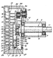
- the figure shows a spiral compressor which mainly consists of a two-part housing 1 with a fixed spiral 2, a moving rotor 3 in this housing with the moving spiral 4 working in conjunction with said fixed spiral, and a crankshaft 5 to drive the rotor 3.
- the crankshaft 5 contains a main shaft 6 which is bearing-mounted by means of ball bearings 7 in a part 8 of the housing 1 and a secondary shaft 9 which is connected to one end of the mainshaft 6, with its geometric axis 10 parallel to but eccentrically in relation to the geometric axis 11 of the main shaft 6.
- a counterweight 12 is connected to the main shaft 6, which is opposite eccentric to the secondary shaft 9.
- the rotor 3 is equipped with a collar 13 which is bearing-mounted around the secondary shaft 9 by means of a bearing 14, for example a ball bearing.
- This collar 13 consists of an opening 15 in the middle of a back wall 16 of the rotor 3.
- sealing means 36 Inside the collar 13 to seal the bearing 14.
- the moving spiral 4 stands on a front wall 17 of the rotor 3 and works in conjunction with the fixed spiral 2 provided on the inner side of a wall 18 which is part of the housing 1.
- a partition wall 19 which connects at the bottom of the rotor 3 and above the opening 15 onto the back wall 16 and together with a part of this back wall 16 forms an oil chamber 20 which extends from under the rotor 3 to above the opening 15 and is thus connected with the bearing 14 via this opening 15.
- This oil chamber is partly filled with oil 21 which can be drained via a draining aperture 23 sealed by means of a plug 22. Filling the oil chamber 20 and checking the oil level therein is done in a known manner via an access 24.
- the partition wall 19 and the part of the back wall 16 of the rotor 3 situated above the oil chamber 20 are connected to the front wall 17 by means of ribs 25.
- cooling ribs 26 are provided on the inside of the partition wall 19 and cooling ribs 27 are provided on the inside of the back wall 16. Opposite the cooling ribs 27 are also provided cooling ribs 28 on the outside of the back wall 16.
- Cooling air is blown over the back side 16 and thus over the cooling ribs 28 by means of a fan 29.
- This fan can be mounted externally or, as is represented in the figure, in the housing 1.
- crankshafts 30 are mounted between the rotor 3 and the housing 1, which are bearing-mounted with one end in a ball bearing 31 which is worked into the housing 1, and which are bearing-mounted with the other end in a ball bearing 32 which is surrounded by a collar 33 on the back wall 16 of the rotor 3.
- Three such crankshaft 30 can for example be provided at an angle of 120° in relation to one another.
- the oil lubrication allows for a higher rotational speed of the rotor 3 than the grease lubrication.
- the compressor can cooperate both horizontally with the crankshaft 5 as represented in the figure and vertically with the crankshaft 5.
- the bearing 14 will obtain a sufficient amount of oil.
Landscapes
- Engineering & Computer Science (AREA)
- Mechanical Engineering (AREA)
- General Engineering & Computer Science (AREA)
- Applications Or Details Of Rotary Compressors (AREA)
- Rotary Pumps (AREA)
Claims (9)
- Spiralverdichter, der ein Gehäuse (1) mit der festen Spirale (2) umfasst; in diesem Gehäuse (1) einen bewegenden Rotor (3) mit der bewegenden Spirale (4), die mit der festen Spirale (2) zusammenwirkt; und eine Kurbelwelle (5), die eine Hauptwelle (6) umfasst, die im Gehäuse (1) gelagert ist und die eine in Bezug zur geometrischen Achse (11) der Hauptwelle (6) exzentrisch angeordnete sekundäre Welle (9) aufweist, die mittels eines Lagers (14) im Rotor (3) gelagert ist; wobei Mittel (30-31-32) vorgesehen sind, um den Rotor (3) daran zu hindern, um sein eigenes Zentrum zu rotieren, derart, dass der Rotor (3) lediglich eine kreisförmige Bewegung um die geometrische Achse (11) der Kurbelwelle (5) ausführen kann, wenn diese Kurbelwelle (5) rotiert, dadurch gekennzeichnet, dass der Rotor (3) mit einer Ölkammer (20) versehen ist, die mittels einer in der Wand der Kammer (20) gegenüber vom Lager (14) angebrachten Öffnung (15) mit dem Lager (14) zwischen der sekundären Welle (9) und dem Rotor (3) in Verbindung steht, wobei die Ölkammer (20) sich von der Unterseite des Rotors (3) bis über diese Öffnung (15) erstreckt.
- Spiralverdichter gemäß Anspruch 1, dadurch gekennzeichnet, dass die Ölkammer (20) teilweise mit Öl gefüllt ist, derart, dass bei der Bewegung des Rotors eine bestimmte Menge auf das Lager (14) geschleudert wird.
- Spiralverdichter gemäß einem der Ansprüche 3 und 4, dadurch gekennzeichnet, dass der Rotor (3) einen Kragen (13) um die das Lager (14) umgebende Öffnung (15) aufweist.
- Spiralverdichter gemäß einem der Ansprüche 1 bis 3, dadurch gekennzeichnet, dass auf der von der Öffnung (15) abgewandten Seite des Lagers (14) Dichtungsmittel (36) zum Abdichten des Lagers (14) vorgesehen sind.
- Spiralverdichter gemäß einem der vorgenannten Ansprüche, dadurch gekennzeichnet, dass die Ölkammer (20) mit Kühlrippen (20) ausgerüstet ist.
- Spiralverdichter gemäß Anspruch 5, dadurch gekennzeichnet, dass Kühlrippen an der Innenseite der Ölkammer (20) vorgesehen sind.
- Spiralverdichter gemäß einem der Ansprüche 5 und 6, dadurch gekennzeichnet, dass Kühlrippen an der Außenseite der Ölkammer (20) vorgesehen sind.
- Spiralverdichter gemäß einem der vorgenannten Ansprüche, dadurch gekennzeichnet, dass er einen Ventilator (29) umfasst, um gekühlte Luft entlang der Außenseite des Rotors (3) zu blasen.
- Spiralverdichter gemäß einem der vorgenannten Ansprüche, dadurch gekennzeichnet, dass die Ölkammer (20) an der Unterseite eine mittels eines Stopfens (22) verschlossene Ablassöffnung (23) aufweist.
Applications Claiming Priority (2)
| Application Number | Priority Date | Filing Date | Title |
|---|---|---|---|
| BE9500600A BE1009475A3 (nl) | 1995-07-06 | 1995-07-06 | Spiraalkompressor. |
| BE9500600 | 1995-07-06 |
Publications (2)
| Publication Number | Publication Date |
|---|---|
| EP0752533A1 EP0752533A1 (de) | 1997-01-08 |
| EP0752533B1 true EP0752533B1 (de) | 2001-08-29 |
Family
ID=3889083
Family Applications (1)
| Application Number | Title | Priority Date | Filing Date |
|---|---|---|---|
| EP96201783A Expired - Lifetime EP0752533B1 (de) | 1995-07-06 | 1996-06-27 | Spiralverdichter |
Country Status (6)
| Country | Link |
|---|---|
| US (1) | US5842842A (de) |
| EP (1) | EP0752533B1 (de) |
| JP (1) | JPH0925884A (de) |
| BE (1) | BE1009475A3 (de) |
| DE (1) | DE69614783T2 (de) |
| ES (1) | ES2161968T3 (de) |
Families Citing this family (12)
| Publication number | Priority date | Publication date | Assignee | Title |
|---|---|---|---|---|
| BE1012016A3 (nl) | 1998-06-02 | 2000-04-04 | Atlas Copco Airpower Nv | Spiraalcompressor. |
| JP2000145669A (ja) * | 1998-11-05 | 2000-05-26 | Toyota Autom Loom Works Ltd | スクロール型圧縮機における旋回スクロールの回転バランス機構 |
| DE19950117C2 (de) * | 1999-10-18 | 2001-08-30 | Knorr Bremse Systeme | Spiralverdichter |
| JP3991810B2 (ja) * | 2002-08-05 | 2007-10-17 | 株式会社豊田自動織機 | スクロール型圧縮機 |
| DE102007043595B4 (de) * | 2007-09-13 | 2009-12-24 | Handtmann Systemtechnik Gmbh & Co. Kg | Verdrängermaschine nach dem Spiralprinzip |
| DE102014107709A1 (de) * | 2014-06-02 | 2015-12-03 | Pfeiffer Vacuum Gmbh | Vakuumpumpe |
| BE1022091B1 (nl) * | 2014-08-14 | 2016-02-15 | Atlas Copco Airpower Naamloze Vennootschap | Spiraalcompressor |
| DE102015220131A1 (de) * | 2015-10-15 | 2017-04-20 | Handtmann Systemtechnik Gmbh & Co. Kg | Verdichtereinrichtung, Antriebsvorrichtung, Kraftfahrzeug |
| US10982672B2 (en) | 2015-12-23 | 2021-04-20 | Emerson Climate Technologies, Inc. | High-strength light-weight lattice-cored additive manufactured compressor components |
| US10557464B2 (en) * | 2015-12-23 | 2020-02-11 | Emerson Climate Technologies, Inc. | Lattice-cored additive manufactured compressor components with fluid delivery features |
| US10634143B2 (en) | 2015-12-23 | 2020-04-28 | Emerson Climate Technologies, Inc. | Thermal and sound optimized lattice-cored additive manufactured compressor components |
| CN106989020B (zh) * | 2017-06-08 | 2019-06-11 | 中国石油大学(华东) | 一种无油润滑涡旋真空泵 |
Family Cites Families (15)
| Publication number | Priority date | Publication date | Assignee | Title |
|---|---|---|---|---|
| US33473A (en) * | 1861-10-15 | Improved stall for animals | ||
| CH586348A5 (de) * | 1975-02-07 | 1977-03-31 | Aginfor Ag | |
| DE2831179A1 (de) * | 1978-07-15 | 1980-01-24 | Leybold Heraeus Gmbh & Co Kg | Verdraengermaschine nach dem spiralprinzip |
| JPS5776201A (en) | 1980-10-31 | 1982-05-13 | Hitachi Ltd | Oil feed device for scroll hydraulic machine |
| JPS5776292A (en) * | 1980-10-31 | 1982-05-13 | Hitachi Ltd | Scroll fluid machine |
| US4337984A (en) * | 1981-01-02 | 1982-07-06 | Ingersoll-Rand Company | Lubrication means for a journal and bearing |
| JPS60192894A (ja) * | 1984-03-13 | 1985-10-01 | Mitsubishi Electric Corp | スクロ−ル圧縮機 |
| JP2522775B2 (ja) * | 1986-11-26 | 1996-08-07 | 株式会社日立製作所 | スクロ−ル流体機械 |
| KR910001824B1 (ko) * | 1987-08-10 | 1991-03-26 | 가부시기가이샤 히다찌세이사꾸쇼 | 스크롤 압축기의 급유장치 |
| US4795321A (en) * | 1987-11-27 | 1989-01-03 | Carrier Corporation | Method of lubricating a scroll compressor |
| US4898522A (en) * | 1988-04-07 | 1990-02-06 | Teledyne Industries, Inc. | System for cooling the rotary engine rotor |
| JP2928632B2 (ja) * | 1990-11-30 | 1999-08-03 | 株式会社日立製作所 | 横形冷媒圧縮機 |
| JP3146751B2 (ja) * | 1993-05-10 | 2001-03-19 | 株式会社豊田自動織機製作所 | 無給油式スクロール型流体機械 |
| JPH06341384A (ja) * | 1993-06-02 | 1994-12-13 | Kobe Steel Ltd | オイルフリースクロール圧縮機 |
| US5466134A (en) * | 1994-04-05 | 1995-11-14 | Puritan Bennett Corporation | Scroll compressor having idler cranks and strengthening and heat dissipating ribs |
-
1995
- 1995-07-06 BE BE9500600A patent/BE1009475A3/nl not_active IP Right Cessation
-
1996
- 1996-06-27 ES ES96201783T patent/ES2161968T3/es not_active Expired - Lifetime
- 1996-06-27 DE DE69614783T patent/DE69614783T2/de not_active Expired - Fee Related
- 1996-06-27 EP EP96201783A patent/EP0752533B1/de not_active Expired - Lifetime
- 1996-07-04 JP JP8174981A patent/JPH0925884A/ja active Pending
- 1996-07-05 US US08/675,829 patent/US5842842A/en not_active Expired - Fee Related
Also Published As
| Publication number | Publication date |
|---|---|
| JPH0925884A (ja) | 1997-01-28 |
| BE1009475A3 (nl) | 1997-04-01 |
| DE69614783T2 (de) | 2002-05-23 |
| US5842842A (en) | 1998-12-01 |
| DE69614783D1 (de) | 2001-10-04 |
| EP0752533A1 (de) | 1997-01-08 |
| ES2161968T3 (es) | 2001-12-16 |
Similar Documents
| Publication | Publication Date | Title |
|---|---|---|
| EP0752533B1 (de) | Spiralverdichter | |
| KR0126627Y1 (ko) | 오일 실드 | |
| US5591018A (en) | Hermetic scroll compressor having a pumped fluid motor cooling means and an oil collection pan | |
| US4496293A (en) | Compressor of the scroll type | |
| EP0122469B1 (de) | Schmiereinrichtung für Verdrängungsanlage mit ineinandergreifenden Spiralelementen | |
| US4666381A (en) | Lubricant distribution system for scroll machine | |
| US7458790B2 (en) | Vacuum pump with improved oil lubrication | |
| CA1202914A (en) | Main bearing lubrication system for scroll machine | |
| US4236878A (en) | Lubrication system for compressor unit | |
| KR19990044128A (ko) | 스크롤 압축기 | |
| PH26207A (en) | Refrigeration compressor | |
| BG62307B1 (bg) | Двигател с вграден редуктор | |
| KR900009224B1 (ko) | 밀폐형 스크롤압축기 | |
| JPS63109291A (ja) | スクロ−ル圧縮機 | |
| EP1673538B1 (de) | Hermetischer verdichter | |
| US4936757A (en) | Multi-section vacuum pump | |
| KR100190141B1 (ko) | 오일안내공이 형성된 밀폐형 왕복동식 압축기 | |
| US2898072A (en) | Lubricating system for refrigerant compressors | |
| US2124239A (en) | Refrigerating apparatus | |
| KR890004931B1 (ko) | 밀폐형 스크로울 압축기 | |
| EP1911975B1 (de) | Versiegelter elektrischer Verdichter | |
| JP2539552B2 (ja) | 密閉形スクロ−ル圧縮機 | |
| US5271247A (en) | Cooling device for a hermetic motor-driven compressor | |
| JPH0463984A (ja) | スクロール圧縮機 | |
| EP0444221A1 (de) | Lotrechtstehender Drehkolbenverdichter |
Legal Events
| Date | Code | Title | Description |
|---|---|---|---|
| PUAI | Public reference made under article 153(3) epc to a published international application that has entered the european phase |
Free format text: ORIGINAL CODE: 0009012 |
|
| AK | Designated contracting states |
Kind code of ref document: A1 Designated state(s): DE ES FR GB IT NL SE |
|
| 17P | Request for examination filed |
Effective date: 19970708 |
|
| 17Q | First examination report despatched |
Effective date: 20000329 |
|
| GRAG | Despatch of communication of intention to grant |
Free format text: ORIGINAL CODE: EPIDOS AGRA |
|
| GRAG | Despatch of communication of intention to grant |
Free format text: ORIGINAL CODE: EPIDOS AGRA |
|
| GRAH | Despatch of communication of intention to grant a patent |
Free format text: ORIGINAL CODE: EPIDOS IGRA |
|
| GRAH | Despatch of communication of intention to grant a patent |
Free format text: ORIGINAL CODE: EPIDOS IGRA |
|
| GRAA | (expected) grant |
Free format text: ORIGINAL CODE: 0009210 |
|
| AK | Designated contracting states |
Kind code of ref document: B1 Designated state(s): DE ES FR GB IT NL SE |
|
| REF | Corresponds to: |
Ref document number: 69614783 Country of ref document: DE Date of ref document: 20011004 |
|
| REG | Reference to a national code |
Ref country code: ES Ref legal event code: FG2A Ref document number: 2161968 Country of ref document: ES Kind code of ref document: T3 |
|
| REG | Reference to a national code |
Ref country code: GB Ref legal event code: IF02 |
|
| ET | Fr: translation filed | ||
| PG25 | Lapsed in a contracting state [announced via postgrant information from national office to epo] |
Ref country code: GB Free format text: LAPSE BECAUSE OF NON-PAYMENT OF DUE FEES Effective date: 20020627 |
|
| PG25 | Lapsed in a contracting state [announced via postgrant information from national office to epo] |
Ref country code: SE Free format text: LAPSE BECAUSE OF NON-PAYMENT OF DUE FEES Effective date: 20020628 Ref country code: ES Free format text: LAPSE BECAUSE OF NON-PAYMENT OF DUE FEES Effective date: 20020628 |
|
| PLBE | No opposition filed within time limit |
Free format text: ORIGINAL CODE: 0009261 |
|
| STAA | Information on the status of an ep patent application or granted ep patent |
Free format text: STATUS: NO OPPOSITION FILED WITHIN TIME LIMIT |
|
| 26N | No opposition filed | ||
| PG25 | Lapsed in a contracting state [announced via postgrant information from national office to epo] |
Ref country code: NL Free format text: LAPSE BECAUSE OF NON-PAYMENT OF DUE FEES Effective date: 20030101 Ref country code: DE Free format text: LAPSE BECAUSE OF NON-PAYMENT OF DUE FEES Effective date: 20030101 |
|
| EUG | Se: european patent has lapsed | ||
| GBPC | Gb: european patent ceased through non-payment of renewal fee |
Effective date: 20020627 |
|
| PG25 | Lapsed in a contracting state [announced via postgrant information from national office to epo] |
Ref country code: FR Free format text: LAPSE BECAUSE OF NON-PAYMENT OF DUE FEES Effective date: 20030228 |
|
| NLV4 | Nl: lapsed or anulled due to non-payment of the annual fee |
Effective date: 20030101 |
|
| REG | Reference to a national code |
Ref country code: FR Ref legal event code: ST |
|
| REG | Reference to a national code |
Ref country code: ES Ref legal event code: FD2A Effective date: 20030711 |
|
| PG25 | Lapsed in a contracting state [announced via postgrant information from national office to epo] |
Ref country code: IT Free format text: LAPSE BECAUSE OF NON-PAYMENT OF DUE FEES;WARNING: LAPSES OF ITALIAN PATENTS WITH EFFECTIVE DATE BEFORE 2007 MAY HAVE OCCURRED AT ANY TIME BEFORE 2007. THE CORRECT EFFECTIVE DATE MAY BE DIFFERENT FROM THE ONE RECORDED. Effective date: 20050627 |