EP0752284B1 - Roll stand with separable roll parting adjustment module - Google Patents
Roll stand with separable roll parting adjustment module Download PDFInfo
- Publication number
- EP0752284B1 EP0752284B1 EP96304851A EP96304851A EP0752284B1 EP 0752284 B1 EP0752284 B1 EP 0752284B1 EP 96304851 A EP96304851 A EP 96304851A EP 96304851 A EP96304851 A EP 96304851A EP 0752284 B1 EP0752284 B1 EP 0752284B1
- Authority
- EP
- European Patent Office
- Prior art keywords
- roll
- sleeves
- gears
- roll stand
- stand
- Prior art date
- Legal status (The legal status is an assumption and is not a legal conclusion. Google has not performed a legal analysis and makes no representation as to the accuracy of the status listed.)
- Expired - Lifetime
Links
Images


Classifications
-
- B—PERFORMING OPERATIONS; TRANSPORTING
- B21—MECHANICAL METAL-WORKING WITHOUT ESSENTIALLY REMOVING MATERIAL; PUNCHING METAL
- B21B—ROLLING OF METAL
- B21B39/00—Arrangements for moving, supporting, or positioning work, or controlling its movement, combined with or arranged in, or specially adapted for use in connection with, metal-rolling mills
-
- B—PERFORMING OPERATIONS; TRANSPORTING
- B21—MECHANICAL METAL-WORKING WITHOUT ESSENTIALLY REMOVING MATERIAL; PUNCHING METAL
- B21B—ROLLING OF METAL
- B21B31/00—Rolling stand structures; Mounting, adjusting, or interchanging rolls, roll mountings, or stand frames
- B21B31/16—Adjusting or positioning rolls
- B21B31/20—Adjusting or positioning rolls by moving rolls perpendicularly to roll axis
- B21B31/22—Adjusting or positioning rolls by moving rolls perpendicularly to roll axis mechanically, e.g. by thrust blocks, inserts for removal
- B21B31/26—Adjusting eccentrically-mounted roll bearings
-
- B—PERFORMING OPERATIONS; TRANSPORTING
- B21—MECHANICAL METAL-WORKING WITHOUT ESSENTIALLY REMOVING MATERIAL; PUNCHING METAL
- B21B—ROLLING OF METAL
- B21B31/00—Rolling stand structures; Mounting, adjusting, or interchanging rolls, roll mountings, or stand frames
-
- B—PERFORMING OPERATIONS; TRANSPORTING
- B21—MECHANICAL METAL-WORKING WITHOUT ESSENTIALLY REMOVING MATERIAL; PUNCHING METAL
- B21B—ROLLING OF METAL
- B21B1/00—Metal-rolling methods or mills for making semi-finished products of solid or profiled cross-section; Sequence of operations in milling trains; Layout of rolling-mill plant, e.g. grouping of stands; Succession of passes or of sectional pass alternations
- B21B1/16—Metal-rolling methods or mills for making semi-finished products of solid or profiled cross-section; Sequence of operations in milling trains; Layout of rolling-mill plant, e.g. grouping of stands; Succession of passes or of sectional pass alternations for rolling wire rods, bars, merchant bars, rounds wire or material of like small cross-section
- B21B1/18—Metal-rolling methods or mills for making semi-finished products of solid or profiled cross-section; Sequence of operations in milling trains; Layout of rolling-mill plant, e.g. grouping of stands; Succession of passes or of sectional pass alternations for rolling wire rods, bars, merchant bars, rounds wire or material of like small cross-section in a continuous process
Definitions
- This invention relates generally to rolling mills for continuously hot rolling single strand products such as bars, rods and the like in a twist-free manner, and is concerned in particular with an improvement in the design of the roll stands used to "size" such products at the delivery end of the mill.
- size and “sizing” refer to the finish rolling of rod and bar products to extremely close tolerances approaching cold drawn tolerances by taking a succession of relatively light reductions on the order of about 1-18% per stand.
- a product "P" with a round cross section as shown in Fig. 2A is rolled through a succession of three successive roll stands 10, 12, and 14 having the axes of their respective work pairs 10a,10a; 12a,12a; and 14a,14a offset by 90° in order to achieve twist-free rolling.
- the work rolls are carried on roll shafts 16 which are journalled for rotation in the eccentric bores of sleeves 18, the latter in turn being journalled for rotation in the housings of the respective roll stands.
- the eccentric sleeves are provided with externally geared peripheries 19 which are engaged by laterally disposed worms 20 carried on adjustment shafts 22. Rotation of the adjustment shafts imparts opposite hand rotation to the eccentric sleeves of the roll shafts of respective roll pairs, thereby achieving symmetrical roll parting adjustments in a manner well known to those skilled in the art.
- the work rolls 10a of the first stand 10 effect a slight reduction on the order of 4 to 18% while imparting a horizontally oriented ovalness to the product as depicted in Fig. 2B.
- a further reduced but vertically oriented ovalness is achieved, as depicted in Fig. 2C.
- the oval shapes depicted in Figure 2B and 2C have been exaggerated for purposes of illustration.
- roll stands 10 and 12 effect very slight changes in cross-sectional shape, with the exiting products being only slightly oval in shape.
- the product is further reduced to achieve a precision round as depicted in Fig. 2D.
- each conventional roll stand includes its own dedicated eccentric sleeve adjustment mechanisms.
- US 4,653,304 describes a rolling stand comprising a pair of supporting shafts for rolling rings, the supporting shafts being adjustably supported at two sides in two parallel roll housings and able to be coupled at one side with drive elements. The arrangement uses eccentric bushings which are rotated by means of a threaded spindle in the roll housing.
- the eccentric sleeves on one side of the roll pass are rotatably coupled to the eccentric sleeves on the opposite side of the roll pass.
- the eccentric sleeve adjusting mechanism is contained within a module detachably connected to the roll stand housing and is positioned to axially engage the eccentric sleeves on only one side of the roll pass.
- the eccentric sleeve adjusting mechanisms are thus completely removed from positions between the successive stands where they would otherwise interfere with close interstand spacing.
- the containment of the eccentric sleeve adjusting mechanisms in detachable modules is also advantageous in that it obviates the expense of providing each roll stand with a dedicated adjustment mechanism.
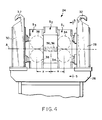
- a sizing train according to the present invention is generally depicted at 24.
- the sizing train is mounted on a portable cradle having a base 26 and end stanchions 28, 30 with hooks 32 which may be engaged by the lift cables of an overhead crane (not shown) when transporting the unit to and from the rolling line.
- the sizing train 24 includes three roll stands S 1 , S 2 and S 3 provided respectively with work roll pairs 34,34; 36,36; and 38,38.
- the work pairs 34,34 and 38,38 are horizontally disposed, whereas the work roll pair 36,36 is vertically disposed to thereby accommodate twist-free rolling of a product directed from left to right along the mill pass line "A".
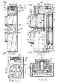
- the roll stands S 1 , S 2 and S 3 have essentially identical internal configurations, and hence an understanding of each can be had by reference to Figures 5-14 which provide various views of roll stand S 1 .
- Roll stand S 1 includes a housing made up of side members 40a, 40b spaced apart by and joined to top and bottom intermediate filler pieces 42, 44 to thereby define a through opening 46.
- Two sets of axially aligned first and second sleeves 48a, 48b are journalled in the housing side members 40a, 40b for rotation about parallel axes.
- the first and second sleeves 48a and 48b of each set are located on opposite sides ofthe through opening 46 and as is best seen in Figure 6, have axially aligned eccentric bores 50.
- a pair of roll shafts 52 extends across the through opening 46 and protrudes from one side of the housing for coupling to a mill drive (not shown).
- Neck portions 52' of the roll shafts are journalled for rotation in the eccentric sleeve bores 50 by means of roller bearings 54.
- the work rolls 34 are located in the through opening 46 and are carried on the roll shafts 52 between the eccentric sleeves 48a, 48b journalled in the housing side members 40a, 40b.
- the work rolls are grooved to define a roll pass aligned with the mill pass line A.
- Yoke assemblies 56a,56b are interposed between the work rolls 34 and the first and second eccentric sleeves 48a,48b of each set.
- the yoke assemblies each include collars 58 which surround the rolls shafts 52, and which are connected as at 60 to the inner ends of the respective eccentric sleeves 48a,48b.
- the collars 58 have confronting integral bridging segments 62 with juxtaposed ends located laterally of the work rolls 34 and interconnected by any convenient means, for example keys 64.
- the yoke assemblies thus serve as couplings which rotatably interconnect the eccentric sleeves 48a, 48b of each set.
- the yoke assemblies lie substantially within the plane of the eccentric sleeves and thus do not contribute to an increase in the width "w" of the housing as measured in the direction of the mill pass line A.
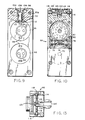
- An eccentric sleeve adjustment module 66 is detachably connected to the housing side member 40a by any convenient means, for example bolts 68.
- the module 66 rotatably supports a pair of gear shafts 70 journalled for rotation about parallel axes.
- the gear shafts 70 have gear plates 72 to which are secured worm gears 74.
- the worm gears 74 in turn are in meshed relationship with a common worm 76 carried on a spindle shaft 78.
- the spindle shaft has an adjustment wheel 80 secured to it at one end.
- the adjustment wheel is accessible via a notched recess 82 in the module side, and has peripherally arranged radial recesses which may be engaged by a tool (not shown) to rotate the spindle shaft and thereby impart simultaneous opposite hand rotation to the worm gears 74.
- Each worm gear 74 is axially engageable with and separably connected to one end of a respective eccentric sleeve 48a by means of a so-called “Oldham coupling” arrangement. More particularly, as can best be seen by reference to Figures 6, 9, 11 and 12, a driving ring 84 is loosely connected in a "floating" relationship to the gear plate 72 by means of shoulder screws 86. The driving ring has two sets of peripheral notches 88, 90. Notches 88 receive and coact in mechanical interengagement with lugs 92 protruding from the gear plate 72.
- the notches 90 receive and similarly coact in mechanical interengagement with lugs 94 protruding in the opposite direction from collars 96 rotatably fixed in relation to and extending axially from the adjacent ends of the respective eccentric sleeves 48a.
- At least one eccentric sleeve (in this case, the sleeve 48a of the upper set) and its respective roll shaft and work roll is shiftable axially with respect to the other shaft and work roll by means of an axial adjustment mechanism generally indicated at 98 in Figure 5.
- This mechanism includes a collar 100 journalled for rotation in the housing side member 40a.
- Collar 100 has an eccentric bore 102 and external oppositely disposed flat-bottomed notches 104 (see Figure 9) aligned with a slot 106 in the housing side member.
- a pin 108 is journalled for rotation in the eccentric bore 102 of the collar 100.
- Pin 108 has a flat spade-like end projection 110 extending into an external groove 112 in the adjacent eccentric sleeve 48a.
- the module 66 includes an upper open-sided recess 114 across which extends a threaded spindle 116 journalled between bearings 118.
- the spindle 116 carries a nut element 120 pivotally connected by integral oppositely protruding pins 122 to the base of a bifurcated element 124, the branches 124' of which are designed to enter the slot 106 in housing side member 40a and to straddle the notches 104 in collar 100.
- rotation of the spindle 116 will act through the nut 120 and the bifurcated element 124 to rotate the collar 100.
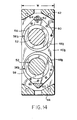
- the overall width "w" of the roll stand housing is dictated primarily by strength considerations and need only be slightly greater than the external diameter of the eccentric sleeves 48a,48b.
- the yoke assemblies 56a,56b which interconnect the eccentric sleeves of each set, and the roll parting and axial adjustment mechanisms contained in the module 66 are all confined within the width w.
- the spacing "x" between the work rolls of stands S 1 and S 2 be minimized, but the spacing "y” between the work rolls of stands S 2 and S 3 also can be similarly minimized.
- the spacing "x" between the axes of roll pairs 34,34 and 36,36 can be minimized to about 240mm, and the spacing "y” between roll pairs 36,36 and 38,38 can be kept to about 260mm, or in general only about 8% greater than "x".
- each module can be coupled alternatively to more than one roll stand.
- the roll stands thus can be more simple in design (not requiring dedicated integral adjustment mechanisms), with concomitant savings in capital investment for the mill operator.
- the eccentric sleeves of a given set may be rotatably coupled by means other than direct mechanical interconnection, including the provision of jointly driven electric or hydraulic motors and the like. The same may be true of the drive mechanism used to rotatably adjust one or both of the first eccentric sleeves of each set.
Applications Claiming Priority (2)
| Application Number | Priority Date | Filing Date | Title |
|---|---|---|---|
| US498630 | 1995-07-06 | ||
| US08/498,630 US5743126A (en) | 1995-07-06 | 1995-07-06 | Roll stand with separable roll parting adjustment module |
Publications (2)
| Publication Number | Publication Date |
|---|---|
| EP0752284A1 EP0752284A1 (en) | 1997-01-08 |
| EP0752284B1 true EP0752284B1 (en) | 2000-04-19 |
Family
ID=23981863
Family Applications (1)
| Application Number | Title | Priority Date | Filing Date |
|---|---|---|---|
| EP96304851A Expired - Lifetime EP0752284B1 (en) | 1995-07-06 | 1996-07-01 | Roll stand with separable roll parting adjustment module |
Country Status (19)
| Country | Link |
|---|---|
| US (1) | US5743126A (ru) |
| EP (1) | EP0752284B1 (ru) |
| JP (1) | JP2867243B2 (ru) |
| KR (1) | KR100225218B1 (ru) |
| CN (1) | CN1066645C (ru) |
| AR (1) | AR002765A1 (ru) |
| AT (1) | ATE191867T1 (ru) |
| AU (1) | AU682997B2 (ru) |
| BR (1) | BR9602998A (ru) |
| CA (1) | CA2179862C (ru) |
| DE (1) | DE69607791T2 (ru) |
| ES (1) | ES2145386T3 (ru) |
| IN (1) | IN192975B (ru) |
| MX (1) | MX9602653A (ru) |
| MY (1) | MY119260A (ru) |
| PT (1) | PT752284E (ru) |
| RU (1) | RU2103082C1 (ru) |
| TW (1) | TW309457B (ru) |
| ZA (1) | ZA965649B (ru) |
Families Citing this family (9)
| Publication number | Priority date | Publication date | Assignee | Title |
|---|---|---|---|---|
| DE19650580A1 (de) * | 1996-12-06 | 1998-06-10 | Schloemann Siemag Ag | Walzgerüst-Exzenterlagerhülsen für Walzentragwellen |
| DE10144743B4 (de) * | 2001-09-11 | 2012-03-15 | Kocks Technik Gmbh & Co. Kg | Walzgerüst zum Walzen von stab- oder rohrförmigem Gut |
| CN100386538C (zh) * | 2005-12-22 | 2008-05-07 | 中冶集团北京冶金设备研究设计总院 | 一种可以实现中心涨缩的传动机构 |
| IT1400261B1 (it) * | 2010-05-26 | 2013-05-24 | Danieli Off Mecc | Sistema di azzeramento gabbia di laminazione. |
| ITUD20110158A1 (it) * | 2011-10-07 | 2013-04-08 | Danieli Off Mecc | Unita' di laminazione |
| CN103949479A (zh) * | 2014-04-17 | 2014-07-30 | 中国重型机械研究院股份公司 | 一种尺寸精密控制棒材轧机的偏心装置 |
| CN104384190B (zh) * | 2014-11-13 | 2016-08-17 | 重庆市龙山金属材料有限公司 | 菱形钢管轧制装置 |
| DE112020002050T5 (de) * | 2019-05-31 | 2022-01-27 | Kabushiki Kaisha Toyota Jidoshokki | Leistungsspeichervorrichtung |
| CN113828382B (zh) * | 2021-09-18 | 2022-11-25 | 北京麦思迪国际医药科技有限公司 | 药学药理辅助实验装置 |
Family Cites Families (9)
| Publication number | Priority date | Publication date | Assignee | Title |
|---|---|---|---|---|
| DE148732C (ru) * | ||||
| US3691810A (en) * | 1971-05-25 | 1972-09-19 | Tadeusz Sendzimir | Individual eccentric control for mill screwdown |
| US3945234A (en) * | 1975-01-02 | 1976-03-23 | Rolf Steinbock | Tandem rolling mill arrangement |
| DE2555446A1 (de) * | 1975-12-10 | 1977-06-16 | Schloemann Siemag Ag | Walzgeruest zum walzen von draht |
| JPS5750565A (en) * | 1980-09-09 | 1982-03-25 | Foster Wheeler Corp | Mixing chamber |
| DE3574463D1 (de) * | 1984-04-28 | 1990-01-04 | Schloemann Siemag Ag | Walzgeruest. |
| JPS6448611A (en) * | 1987-08-18 | 1989-02-23 | Nippon Kokan Kk | Chockless rolling mill |
| EP0357107A3 (en) * | 1988-08-31 | 1990-08-22 | CASAGRANDE SpA | Cantilevered rolling mill assembly |
| JP3041665B2 (ja) * | 1993-08-24 | 2000-05-15 | 大同特殊鋼株式会社 | 圧延装置 |
-
1995
- 1995-07-06 US US08/498,630 patent/US5743126A/en not_active Expired - Lifetime
-
1996
- 1996-06-25 TW TW085107632A patent/TW309457B/zh not_active IP Right Cessation
- 1996-06-25 CA CA002179862A patent/CA2179862C/en not_active Expired - Fee Related
- 1996-06-28 MY MYPI96002644A patent/MY119260A/en unknown
- 1996-07-01 PT PT96304851T patent/PT752284E/pt unknown
- 1996-07-01 AT AT96304851T patent/ATE191867T1/de active
- 1996-07-01 EP EP96304851A patent/EP0752284B1/en not_active Expired - Lifetime
- 1996-07-01 DE DE69607791T patent/DE69607791T2/de not_active Expired - Lifetime
- 1996-07-01 ES ES96304851T patent/ES2145386T3/es not_active Expired - Lifetime
- 1996-07-02 IN IN1466DE1996 patent/IN192975B/en unknown
- 1996-07-02 JP JP8189957A patent/JP2867243B2/ja not_active Expired - Fee Related
- 1996-07-03 ZA ZA965649A patent/ZA965649B/xx unknown
- 1996-07-04 AU AU58365/96A patent/AU682997B2/en not_active Ceased
- 1996-07-05 BR BR9602998A patent/BR9602998A/pt not_active IP Right Cessation
- 1996-07-05 MX MX9602653A patent/MX9602653A/es not_active IP Right Cessation
- 1996-07-05 KR KR1019960027196A patent/KR100225218B1/ko not_active IP Right Cessation
- 1996-07-05 RU RU96115401A patent/RU2103082C1/ru not_active IP Right Cessation
- 1996-07-05 AR ARP960103471A patent/AR002765A1/es unknown
- 1996-07-08 CN CN96108844A patent/CN1066645C/zh not_active Expired - Fee Related
Also Published As
| Publication number | Publication date |
|---|---|
| ZA965649B (en) | 1997-01-27 |
| CN1140638A (zh) | 1997-01-22 |
| CA2179862C (en) | 1999-08-24 |
| JP2867243B2 (ja) | 1999-03-08 |
| KR100225218B1 (ko) | 1999-10-15 |
| ATE191867T1 (de) | 2000-05-15 |
| ES2145386T3 (es) | 2000-07-01 |
| PT752284E (pt) | 2000-10-31 |
| AR002765A1 (es) | 1998-04-29 |
| DE69607791D1 (de) | 2000-05-25 |
| US5743126A (en) | 1998-04-28 |
| RU2103082C1 (ru) | 1998-01-27 |
| TW309457B (ru) | 1997-07-01 |
| AU5836596A (en) | 1997-01-16 |
| KR970005426A (ko) | 1997-02-19 |
| EP0752284A1 (en) | 1997-01-08 |
| IN192975B (ru) | 2004-06-19 |
| BR9602998A (pt) | 1998-04-28 |
| JPH09220602A (ja) | 1997-08-26 |
| CA2179862A1 (en) | 1997-01-07 |
| DE69607791T2 (de) | 2000-08-10 |
| MX9602653A (es) | 1997-06-28 |
| CN1066645C (zh) | 2001-06-06 |
| MY119260A (en) | 2005-04-30 |
| AU682997B2 (en) | 1997-10-23 |
Similar Documents
| Publication | Publication Date | Title |
|---|---|---|
| US3336781A (en) | Rolling mill | |
| US4653304A (en) | Rolling stand | |
| EP0752284B1 (en) | Roll stand with separable roll parting adjustment module | |
| RU2687522C9 (ru) | Многоклетьевой прокатный стан для стержневых изделий, содержащий клети с тремя валками, имеющими электропривод | |
| US5144828A (en) | Combined light-section mill and wire mill | |
| US4559990A (en) | Continuous casting and rolling device | |
| EP0287674B1 (en) | Roll driving apparatus for rolling mills | |
| US6209376B1 (en) | Adjustable single/double shaft driven metal press mill | |
| US6945084B2 (en) | Rolling mill for rolling or sizing metal pipes | |
| CN104884181B (zh) | 轧制站、轧制厂和轧制工艺 | |
| EP1019204A1 (en) | Rolling mill stand | |
| JPH06210309A (ja) | ロールスタンド | |
| CN113634633B (zh) | 结构用钢双流辊压成型装置 | |
| EP1030750B1 (en) | Carousel winding reel | |
| EP0154249B1 (de) | Walzgerüst mit auf ein Walzentragwellenpaar einseitig (fliegend) aufgesestzten Walzringen | |
| US4411304A (en) | Driving roller stand for continuous casting plants | |
| US1950573A (en) | Rolling mill | |
| JPH1157813A (ja) | 圧延スタンドの要素及びそれを用いて得られる圧延スタンド | |
| US3575028A (en) | Rolling mills | |
| RU2180873C2 (ru) | Многоклетьевой прокатный стан | |
| RU2009741C1 (ru) | Прокатная клеть | |
| SU1065046A1 (ru) | Клеть редукционно-калибровочного стана | |
| EP0726100B1 (en) | Rolling unit | |
| RU2056957C1 (ru) | Прокатный стан | |
| JP2006326602A (ja) | 圧延機 |
Legal Events
| Date | Code | Title | Description |
|---|---|---|---|
| PUAI | Public reference made under article 153(3) epc to a published international application that has entered the european phase |
Free format text: ORIGINAL CODE: 0009012 |
|
| AK | Designated contracting states |
Kind code of ref document: A1 Designated state(s): AT BE CH DE ES FR GB IT LI LU PT SE |
|
| 17P | Request for examination filed |
Effective date: 19970612 |
|
| 17Q | First examination report despatched |
Effective date: 19990119 |
|
| GRAG | Despatch of communication of intention to grant |
Free format text: ORIGINAL CODE: EPIDOS AGRA |
|
| GRAG | Despatch of communication of intention to grant |
Free format text: ORIGINAL CODE: EPIDOS AGRA |
|
| GRAH | Despatch of communication of intention to grant a patent |
Free format text: ORIGINAL CODE: EPIDOS IGRA |
|
| GRAH | Despatch of communication of intention to grant a patent |
Free format text: ORIGINAL CODE: EPIDOS IGRA |
|
| GRAA | (expected) grant |
Free format text: ORIGINAL CODE: 0009210 |
|
| ITF | It: translation for a ep patent filed |
Owner name: BARZANO' E ZANARDO ROMA S.P.A. |
|
| AK | Designated contracting states |
Kind code of ref document: B1 Designated state(s): AT BE CH DE ES FR GB IT LI LU PT SE |
|
| PG25 | Lapsed in a contracting state [announced via postgrant information from national office to epo] |
Ref country code: LI Free format text: LAPSE BECAUSE OF FAILURE TO SUBMIT A TRANSLATION OF THE DESCRIPTION OR TO PAY THE FEE WITHIN THE PRESCRIBED TIME-LIMIT Effective date: 20000419 Ref country code: CH Free format text: LAPSE BECAUSE OF FAILURE TO SUBMIT A TRANSLATION OF THE DESCRIPTION OR TO PAY THE FEE WITHIN THE PRESCRIBED TIME-LIMIT Effective date: 20000419 Ref country code: BE Free format text: LAPSE BECAUSE OF FAILURE TO SUBMIT A TRANSLATION OF THE DESCRIPTION OR TO PAY THE FEE WITHIN THE PRESCRIBED TIME-LIMIT Effective date: 20000419 |
|
| REF | Corresponds to: |
Ref document number: 191867 Country of ref document: AT Date of ref document: 20000515 Kind code of ref document: T |
|
| REG | Reference to a national code |
Ref country code: CH Ref legal event code: EP |
|
| REF | Corresponds to: |
Ref document number: 69607791 Country of ref document: DE Date of ref document: 20000525 |
|
| ET | Fr: translation filed | ||
| REG | Reference to a national code |
Ref country code: ES Ref legal event code: FG2A Ref document number: 2145386 Country of ref document: ES Kind code of ref document: T3 |
|
| REG | Reference to a national code |
Ref country code: PT Ref legal event code: SC4A Free format text: AVAILABILITY OF NATIONAL TRANSLATION Effective date: 20000718 Ref country code: CH Ref legal event code: PL |
|
| PLBE | No opposition filed within time limit |
Free format text: ORIGINAL CODE: 0009261 |
|
| STAA | Information on the status of an ep patent application or granted ep patent |
Free format text: STATUS: NO OPPOSITION FILED WITHIN TIME LIMIT |
|
| 26N | No opposition filed | ||
| REG | Reference to a national code |
Ref country code: GB Ref legal event code: IF02 |
|
| REG | Reference to a national code |
Ref country code: GB Ref legal event code: 732E Free format text: REGISTERED BETWEEN 20110310 AND 20110316 |
|
| REG | Reference to a national code |
Ref country code: DE Ref legal event code: R081 Ref document number: 69607791 Country of ref document: DE Owner name: SIEMENS INDUSTRY, INC. (N. D. GES. D. STAATES , US Free format text: FORMER OWNER: MORGAN CONSTRUCTION CO., WORCESTER, US Effective date: 20110209 |
|
| REG | Reference to a national code |
Ref country code: ES Ref legal event code: PC2A Owner name: SIEMENS INDUSTRY, INC. Effective date: 20110428 |
|
| REG | Reference to a national code |
Ref country code: FR Ref legal event code: TP |
|
| PGFP | Annual fee paid to national office [announced via postgrant information from national office to epo] |
Ref country code: LU Payment date: 20120720 Year of fee payment: 17 |
|
| PGFP | Annual fee paid to national office [announced via postgrant information from national office to epo] |
Ref country code: GB Payment date: 20120709 Year of fee payment: 17 Ref country code: SE Payment date: 20120710 Year of fee payment: 17 |
|
| PGFP | Annual fee paid to national office [announced via postgrant information from national office to epo] |
Ref country code: FR Payment date: 20120802 Year of fee payment: 17 Ref country code: ES Payment date: 20120830 Year of fee payment: 17 Ref country code: IT Payment date: 20120726 Year of fee payment: 17 Ref country code: DE Payment date: 20120906 Year of fee payment: 17 |
|
| PGFP | Annual fee paid to national office [announced via postgrant information from national office to epo] |
Ref country code: PT Payment date: 20120102 Year of fee payment: 17 |
|
| PGFP | Annual fee paid to national office [announced via postgrant information from national office to epo] |
Ref country code: AT Payment date: 20120615 Year of fee payment: 17 |
|
| REG | Reference to a national code |
Ref country code: PT Ref legal event code: MM4A Free format text: LAPSE DUE TO NON-PAYMENT OF FEES Effective date: 20140102 |
|
| REG | Reference to a national code |
Ref country code: SE Ref legal event code: EUG |
|
| REG | Reference to a national code |
Ref country code: AT Ref legal event code: MM01 Ref document number: 191867 Country of ref document: AT Kind code of ref document: T Effective date: 20130701 |
|
| GBPC | Gb: european patent ceased through non-payment of renewal fee |
Effective date: 20130701 |
|
| REG | Reference to a national code |
Ref country code: DE Ref legal event code: R119 Ref document number: 69607791 Country of ref document: DE Effective date: 20140201 |
|
| REG | Reference to a national code |
Ref country code: FR Ref legal event code: ST Effective date: 20140331 |
|
| PG25 | Lapsed in a contracting state [announced via postgrant information from national office to epo] |
Ref country code: SE Free format text: LAPSE BECAUSE OF NON-PAYMENT OF DUE FEES Effective date: 20130702 Ref country code: GB Free format text: LAPSE BECAUSE OF NON-PAYMENT OF DUE FEES Effective date: 20130701 Ref country code: DE Free format text: LAPSE BECAUSE OF NON-PAYMENT OF DUE FEES Effective date: 20140201 |
|
| PG25 | Lapsed in a contracting state [announced via postgrant information from national office to epo] |
Ref country code: IT Free format text: LAPSE BECAUSE OF NON-PAYMENT OF DUE FEES Effective date: 20130701 Ref country code: AT Free format text: LAPSE BECAUSE OF NON-PAYMENT OF DUE FEES Effective date: 20130701 Ref country code: FR Free format text: LAPSE BECAUSE OF NON-PAYMENT OF DUE FEES Effective date: 20130731 |
|
| PG25 | Lapsed in a contracting state [announced via postgrant information from national office to epo] |
Ref country code: PT Free format text: LAPSE BECAUSE OF NON-PAYMENT OF DUE FEES Effective date: 20140102 |
|
| REG | Reference to a national code |
Ref country code: ES Ref legal event code: FD2A Effective date: 20140905 |
|
| PG25 | Lapsed in a contracting state [announced via postgrant information from national office to epo] |
Ref country code: ES Free format text: LAPSE BECAUSE OF NON-PAYMENT OF DUE FEES Effective date: 20130702 |
|
| PG25 | Lapsed in a contracting state [announced via postgrant information from national office to epo] |
Ref country code: LU Free format text: LAPSE BECAUSE OF NON-PAYMENT OF DUE FEES Effective date: 20130701 |