EP0751448B1 - Vanne de régulation de débit - Google Patents
Vanne de régulation de débit Download PDFInfo
- Publication number
- EP0751448B1 EP0751448B1 EP19950120530 EP95120530A EP0751448B1 EP 0751448 B1 EP0751448 B1 EP 0751448B1 EP 19950120530 EP19950120530 EP 19950120530 EP 95120530 A EP95120530 A EP 95120530A EP 0751448 B1 EP0751448 B1 EP 0751448B1
- Authority
- EP
- European Patent Office
- Prior art keywords
- valve
- cone
- flow control
- control valve
- throttle point
- Prior art date
- Legal status (The legal status is an assumption and is not a legal conclusion. Google has not performed a legal analysis and makes no representation as to the accuracy of the status listed.)
- Expired - Lifetime
Links
Images

Classifications
-
- G—PHYSICS
- G05—CONTROLLING; REGULATING
- G05D—SYSTEMS FOR CONTROLLING OR REGULATING NON-ELECTRIC VARIABLES
- G05D7/00—Control of flow
- G05D7/01—Control of flow without auxiliary power
- G05D7/0106—Control of flow without auxiliary power the sensing element being a flexible member, e.g. bellows, diaphragm, capsule
-
- Y—GENERAL TAGGING OF NEW TECHNOLOGICAL DEVELOPMENTS; GENERAL TAGGING OF CROSS-SECTIONAL TECHNOLOGIES SPANNING OVER SEVERAL SECTIONS OF THE IPC; TECHNICAL SUBJECTS COVERED BY FORMER USPC CROSS-REFERENCE ART COLLECTIONS [XRACs] AND DIGESTS
- Y10—TECHNICAL SUBJECTS COVERED BY FORMER USPC
- Y10T—TECHNICAL SUBJECTS COVERED BY FORMER US CLASSIFICATION
- Y10T137/00—Fluid handling
- Y10T137/7722—Line condition change responsive valves
- Y10T137/7781—With separate connected fluid reactor surface
- Y10T137/7784—Responsive to change in rate of fluid flow
- Y10T137/7787—Expansible chamber subject to differential pressures
- Y10T137/7788—Pressures across fixed choke
Definitions
- the invention relates to a flow control valve according to the preamble of claim 1.
- valve used as a flow regulator has a certain nominal flow at maximum opening on. This highest possible flow is too large for many applications. Because of this point Such flow regulators often have a device for limiting the flow.
- the flow limitation is achieved by a stroke limitation. Due to this stroke limitation, however, is now only a smaller adjustment range is available, which is disadvantageous with regard to the control properties.
- DE-A-2 705 891 discloses a control valve with an automatic Regulation of the flow rate of the flowing medium, in which the flow opening is one in the valve housing arranged valve seat can be influenced by a valve cone is one with the difference of the pressures in front of and behind one, stepless in the flow path adjustable orifice and a setpoint containing actuator is coupled, the Orifice plate through one in the valve body on the valve cone arranged opposite side of the valve seat, in turn, if necessary, by one in a control loop lying actuator adjustable throttle body is formed.
- the invention has for its object to provide a compact flow control valve that as Pressure control valve makes the flow independent of the differential pressure, so that the flow is a is a clear function of the valve opening degree, and its flow limitation is designed so that the full adjustment range is retained.
- 1 denotes a flow control valve, through the inlet space 2 of which the Flow medium enters the flow control valve 1 and through the outlet space 3 that Flow medium leaves the flow control valve 1 again, as shown by arrows is.
- a first throttle point is formed by a cone 4, which has a first opening 5 a double seat cage 6 cooperates.
- the cone 4 is movable relative to the double seat cage 6, which enables the valve opening degree to be adjusted.
- the double seat cage 6 is firmly connected to a valve housing 7. At the first opening 5 on the opposite side, the double seat cage 6 has a second opening 8. Relative to this Opening 8, a control cone 9 is movable. This control cone 9 is by means of a rod 10 with a Membrane 11 connected. This membrane 11 is part of a hydraulic drive 12 which Control cone 9 controls relative to the opening 8. This control is made possible by the fact that Membrane 11, on the one hand, the inlet pressure and, on the other hand, the pressure within the double seat cage 6 Act. In order to achieve this effect, a first pressure chamber 13 is provided, which has a Line 14 is connected to the inlet space 2. A second pressure chamber 15 is in the Rod 10 existing bore 16 and a transverse bore 17 with the space 18 within the Double seat cage 6 connected.
- a guide housing 19 is connected, on the one hand, the leadership of the Control cone 9 serves, on the other hand, serves as a support for a regulator spring 20.
- This regulator spring 20 determines the setpoint of the pressure difference to which this device regulates. Their strength adds up that force which the control cone 9 has on the membrane 11. This force is opposed to that Force resulting from the pressure p1 prevailing in the inlet space 2. If the pressure p1 rises in Inlet space 2, the pressure in the pressure chamber 13 also increases. This increasing pressure moves the Diaphragm 11 against the regulator spring 20 until there is a balance of forces again.
- This first throttle point serves as the actual adjusting element for the flow.
- this first throttle point designed so that a limitation of the flow without a Stroke limitation is possible, so that the full stroke can always take place, which in terms of Control properties is favorable. This is achieved by designing the cone 4.
- the adjusting element for the flow consists of this cone 4, which is attached to a valve spindle 21 is.
- the flow can be changed in a known manner by axial movement of the valve spindle 21 become.
- a valve drive of any type, not shown in FIG. 1, is used for this purpose.
- This Valve drive enables a stroke H of the spindle between the two end positions “closed” and “fully open”.
- the valve drive is usually continuous, so that any between the two end positions Intermediate positions are possible.
- the cone 4 consists of a first conical part 22 and rigid on the valve spindle 21 a second cone part 23 that can be positioned axially differently relative to it the first cone part 22 and the second cone part 23 can thereby be changed.
- the execution type this relative positionability can be different. 1 is one possible Execution type shown.
- the valve spindle 21 points in the area in which the second Cone part 23 is seated, a thread 24.
- the cone part 23 has one in its inner bore suitable thread.
- a pin 25 is fixed, which engages in a guide groove 26, the is incorporated in a bolt 27.
- the bolt 27 is firmly connected to the double seat cage 6.
- This arrangement ensures that when the valve spindle 21 rotates Distance between the first cone part 22 and the second cone part 23 changed. When rotating in the the distance increases in one direction and when rotating in the opposite direction the distance decreases.
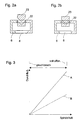
- FIGS. 2a and 2b in the same reference numerals as in FIG. 1, they also mean the same parts, different distances between the cone parts 22, 23 are shown. With the same position of the lower cone part 22 connected to the valve spindle 21, the positions are of the upper cone part 23 different. 2a is the distance between the two cone parts 22, 23 large, in Fig. 2b it is much smaller. It follows that despite the same spindle position Flow in the case of FIG. 2b is smaller than in the case of FIG. 2a.
- the adjustment of the distance between the cone parts 22, 23 by a rotary movement of the Valve spindle 21 is achieved in that a gear 28 is fixed with the valve spindle 21 connected is. In the ring gear of this gear 28 engages a shaft 29 attached Worm gear 30 on.
- the shaft 29 is either by hand or advantageously not by one shown adjusting motor driven.
- the motorization of the adjustment enables the Remote adjustment.
- a controller can effect the adjustment. That is in larger plants advantageous if several flow control valves 1 are to be controlled. So that's it, for example possible to control the volume flow remotely through a control center.
- This solution opens up new possibilities for the central control of larger plants. For example, a District heating plant influence the maximum limitation of the volume flow at the customers and thus to special situations such as an extraordinary cold period or reduced performance in the District heating plant react.
- the flow control valve 1 shown is designed so that it is when the valve drive is not actuated automatically runs to the "closed" end position.
- a compression spring 31 is used for this in a known manner, which are on the one hand on the valve housing 7 and on the other hand connected to the valve spindle 21 Pressure plate 32 supports.
- control cone 9 has a bore 33 which the Pressure relief serves. By means of this pressure relief, the pressure on the control cone 9 acting force compensated.
- a flow diagram is shown in FIG. With lines, the dependence of the flow is represented by the spindle stroke.
- a first curve A shows the flow characteristic for a large one
- the distance between the two cone parts 22, 23 according to FIG. 2a and a second curve B shows them at one smaller distance according to FIG. 2b.
- the nominal flow through the flow control valve 1 is given by the largest adjustable Distance between the cone parts 22, 23 with the greatest stroke of the valve spindle 21 compared to the closed position. By reducing the distance between the cone parts 22, 23 one finds the entire adjustment range Valve stem 21 effective reduction in flow instead.
- valve spindle 21 Is at the greatest possible distance between the cone parts 22, 23 and at every smaller distance the full stroke of the valve spindle 21 is available. This ensures that the full adjustment range the valve spindle 21, ie the full control range, is always available.
Landscapes
- General Physics & Mathematics (AREA)
- Engineering & Computer Science (AREA)
- Automation & Control Theory (AREA)
- Physics & Mathematics (AREA)
- Magnetically Actuated Valves (AREA)
- Lift Valve (AREA)
- Fluid-Driven Valves (AREA)
- Control Of Fluid Pressure (AREA)
- Sliding Valves (AREA)
- Flow Control (AREA)
- Temperature-Responsive Valves (AREA)
- Safety Valves (AREA)
- Valve-Gear Or Valve Arrangements (AREA)
Claims (7)
- Vanne de régulation de débit (1) comportant un premier étranglement (8,9), au moyen duquel une différence de pression au niveau d'un second étranglement (4,5) est réglable sur une valeur constante, cette régulation s'effectuant au moyen d'un dispositif d'entraínement hydraulique (12), qui comporte une membrane (11), dont une face forme une paroi d'une première chambre de pression (13), qui est reliée à une chambre d'admission (2) de la soupape de régulation de débit (1) et dont la seconde face forme une paroi d'une seconde chambre de pression (4), qui est reliée à une chambre (18) en arrière du second étranglement (4,5), cette membrane (11) étant reliée par l'intermédiaire d'une tige (10) à un cône de régulation (9), qui fait partie du premier étranglement (8,9), etcaractérisée en ce que le cône déplaçable (4)a. le second étranglement (4,5) étant logé dans le même boítier de vanne (7) que le premier étranglement,b. le second étranglement (4,5) possédant un cône (4) déplaçable axialement et progressivement par rapport à une ouverture (5) à l'aide d'une tige de vanne (21) au moyen d'un dispositif d'entraínement de la vanne,c. est constitué par au moins deux parties individuelles (22,23) déplaçables axialement l'une par rapport à l'autre,d. dont la distance réciproque permet de modifier la surface transversale active de l'étranglement (4,5).
- Vanne de régulation de débit (1) selon la revendication 1, caractérisée en ce qu'un premier élément (22) du cône est relié rigidement à la tige de vanne (21), tandis que la seconde partie (23) du cône est fixée sur la tige de vanne (21) de manière à être déplaçable axialement.
- Vanne de régulation de débit selon la revendication 2, caractérisée en ce que la seconde partie (23) du cône possède, dans un perçage intérieur, un filetage, qui engrène avec le filetage situé sur la tige de vanne (21).
- Vanne de régulation de débit (1) selon la revendication 3, caractérisée en ce que la seconde partie (23) du cône est retenue de telle sorte qu'elle ne peut pas tourner conjointement lors de la rotation de la tige de vanne (21).
- Vanne de régulation de débit (1) selon la revendication 4, caractérisée en ce que le système de blocage en rotation de la seconde partie (23) du cône est formé par une tige (25) qui est fixée sur la partie (23) du cône et qui s'engage dans une gorge (26) qui est fixe par rapport au boítier de vanne (7).
- Vanne de régulation de débit (1) selon l'une des revendications 2 à 5, caractérisée en ce que le réglage de la distance entre les parties (21,23) du cône s'effectue au moyen d'un mouvement de rotation qui est transmis à la tige de vanne (21) à partir d'un arbre rotatif (29) comportant une roue à vis sans fin (30) fixée sur cet arbre, et ce au moyen d'un pignon (28), qui est fixé à la tige de vanne (21) et engrène avec la roue à vis sans fin (30).
- Vanne de régulation de débit (1) selon la revendication 6, caractérisée en ce que l'arbre (29) peut être entraíné en rotation par un servomoteur et que le servomoteur peut être commandé par un régulateur.
Priority Applications (1)
| Application Number | Priority Date | Filing Date | Title |
|---|---|---|---|
| SI9530494T SI0751448T1 (en) | 1995-06-28 | 1995-12-27 | Flow control valve |
Applications Claiming Priority (3)
| Application Number | Priority Date | Filing Date | Title |
|---|---|---|---|
| CH189195 | 1995-06-28 | ||
| CH1891/95 | 1995-06-28 | ||
| CH189195 | 1995-06-28 |
Publications (3)
| Publication Number | Publication Date |
|---|---|
| EP0751448A2 EP0751448A2 (fr) | 1997-01-02 |
| EP0751448A3 EP0751448A3 (fr) | 1998-06-03 |
| EP0751448B1 true EP0751448B1 (fr) | 2001-03-14 |
Family
ID=4221023
Family Applications (1)
| Application Number | Title | Priority Date | Filing Date |
|---|---|---|---|
| EP19950120530 Expired - Lifetime EP0751448B1 (fr) | 1995-06-28 | 1995-12-27 | Vanne de régulation de débit |
Country Status (11)
| Country | Link |
|---|---|
| US (1) | US5775369A (fr) |
| EP (1) | EP0751448B1 (fr) |
| AT (1) | ATE199789T1 (fr) |
| CA (1) | CA2180062C (fr) |
| CZ (1) | CZ289630B6 (fr) |
| DE (1) | DE59509096D1 (fr) |
| DK (1) | DK0751448T3 (fr) |
| FI (1) | FI110635B (fr) |
| PL (1) | PL180101B1 (fr) |
| RU (1) | RU2161815C2 (fr) |
| SI (1) | SI0751448T1 (fr) |
Cited By (4)
| Publication number | Priority date | Publication date | Assignee | Title |
|---|---|---|---|---|
| DE102013107762A1 (de) * | 2013-07-22 | 2015-01-22 | Oventrop Gmbh & Co. Kg | Durchflussregelventil |
| DE102016120565A1 (de) | 2016-10-27 | 2018-05-03 | Samson Ag | Volumenstromregler zur Volumenstromregelung ohne Hilfsenergie |
| DE102017102308A1 (de) | 2017-02-07 | 2018-08-09 | Oventrop Gmbh & Co. Kg | Ventil mit einer Einrichtung zur Voreinstellung des Strömungskanalquerschnittes |
| EP3527862A1 (fr) | 2018-02-19 | 2019-08-21 | Oventrop GmbH & Co. KG | Soupape pourvue d'un dispositif de présélection de la section du canal d'écoulement |
Families Citing this family (25)
| Publication number | Priority date | Publication date | Assignee | Title |
|---|---|---|---|---|
| EP0911714A1 (fr) * | 1997-10-20 | 1999-04-28 | Electrowatt Technology Innovation AG | Vanne de réglage de débit avec un régulateur de pression intégré |
| FR2780170B1 (fr) * | 1998-06-19 | 2000-08-11 | Aerospatiale | Dispositif autonome de limitation du debit d'un fluide dans une canalisation et circuit de carburant pour aeronef comportant un tel dispositif |
| US6827100B1 (en) | 1999-08-17 | 2004-12-07 | Belimo Holding Ag | Pressure independent control valve |
| DE10114995C1 (de) * | 2001-03-26 | 2002-08-08 | F W Oventrop Gmbh & Co Kg | Regulierventil mit Druckentlastung |
| US6662823B2 (en) * | 2001-11-05 | 2003-12-16 | Samyang Comprehensive Valve Co., Ltd. | Auto flow regulator |
| AT413435B (de) * | 2003-02-20 | 2006-02-15 | Seebacher Theodor | Vorrichtung zum regeln der durchflussmenge einer flüssigkeit, insbesondere des wärmeträgers einer warmwasserheizung |
| CN101057097B (zh) * | 2004-08-02 | 2010-12-08 | 贝利莫控股公司 | 压力独立的控制阀 |
| AT501421B1 (de) * | 2004-12-23 | 2007-03-15 | Seebacher Theodor Ernst | Vorrichtung zum anschliessen eines verbraucherstranges an eine versorgungsleitung, insbesondere eines wasserleitungsnetzes |
| US7770595B2 (en) | 2006-04-27 | 2010-08-10 | Sko Flo Industries, Inc. | Flow control valve |
| EP2021744A4 (fr) * | 2006-04-28 | 2015-09-02 | Sko Flo Ind Inc | Appareil de mesure d'écoulement |
| DE102007009822B3 (de) * | 2007-02-28 | 2008-05-21 | Samson Ag | Volumenstromregler zur Volumenstromregelung ohne Hilfsenergie |
| ITMO20080043A1 (it) * | 2008-02-19 | 2009-08-20 | P A S R L | Valvola di by-pass e di regolazione pressione perfezionata. |
| DE102010046641A1 (de) * | 2010-09-25 | 2012-03-29 | Arne Feldmeier | Verfahren und Vorrichtung zur Volumenstrombestimmung fluiddurchströmter Leitungsnetze |
| US8833384B2 (en) | 2012-08-06 | 2014-09-16 | Schneider Electric Buildings, Llc | Advanced valve actuation system with integral freeze protection |
| US9534795B2 (en) | 2012-10-05 | 2017-01-03 | Schneider Electric Buildings, Llc | Advanced valve actuator with remote location flow reset |
| US10295080B2 (en) | 2012-12-11 | 2019-05-21 | Schneider Electric Buildings, Llc | Fast attachment open end direct mount damper and valve actuator |
| CN102979936A (zh) * | 2012-12-28 | 2013-03-20 | 南京华宁阀门有限公司 | 一种高压压缩空气调节阀 |
| US10007239B2 (en) | 2013-03-15 | 2018-06-26 | Schneider Electric Buildings Llc | Advanced valve actuator with integral energy metering |
| EP2971883B8 (fr) | 2013-03-15 | 2020-07-15 | Schneider Electric Buildings, LLC | Actionneur de soupape perfectionné à retour d'écoulement réel |
| ITMI20130973A1 (it) * | 2013-06-13 | 2014-12-14 | Fimcim Spa | Valvola di controllo |
| RU2637074C2 (ru) * | 2013-07-22 | 2017-11-29 | Овентроп Гмбх Унд Ко.Кг | Клапан регулирования расхода |
| EP2937759B1 (fr) | 2014-04-24 | 2018-04-04 | Siemens Schweiz AG | Vanne de contrôle indépendante de la pression |
| EP3223105B1 (fr) * | 2016-03-24 | 2018-11-14 | Honeywell Technologies Sarl | Soupape de régulation de flux |
| IT201900003389A1 (it) * | 2019-03-08 | 2020-09-08 | Giacomini Spa | Gruppo di regolazione a cartuccia con camera di compensazione e valvola idraulica comprendente il gruppo di regolazione a cartuccia. |
| CN110440040A (zh) * | 2019-08-07 | 2019-11-12 | 沈阳宏奇热力设备制造有限公司 | 管道差压器 |
Family Cites Families (16)
| Publication number | Priority date | Publication date | Assignee | Title |
|---|---|---|---|---|
| DE508732C (de) * | 1930-10-01 | Butzke Bernhard Joseph Akt Ges | Niederschraubventil | |
| US2623331A (en) * | 1950-08-01 | 1952-12-30 | Agro Phosphate Company | Diaphragm type of pressure regulators |
| CH313023A (de) * | 1950-10-06 | 1956-03-15 | Apex Trinidad Oilfields Limite | Steuerorgan für Flüssigkeiten und Gase |
| US3470896A (en) * | 1965-01-07 | 1969-10-07 | Jay P Au Werter | Parallel line fluid system with meter regulating valve |
| US3344805A (en) * | 1965-03-24 | 1967-10-03 | Fischer & Porter Co | Automatic flow rate control system |
| US3428080A (en) * | 1966-02-21 | 1969-02-18 | Fisher Governor Co | Flow control device |
| US3476147A (en) * | 1966-02-21 | 1969-11-04 | Aro Corp | Two-stage control throttle mechanism |
| US3656689A (en) * | 1970-12-16 | 1972-04-18 | Weatherhead Co | Modulating valve |
| US3699999A (en) * | 1971-03-08 | 1972-10-24 | Gpe Controls Inc | Vertical jet breather valve |
| US3904167A (en) * | 1973-07-02 | 1975-09-09 | Joseph Touch | Electric water faucet |
| US4114850A (en) * | 1976-07-12 | 1978-09-19 | Honeywell Inc. | Modulating plug valve |
| DE2705891B2 (de) * | 1977-02-11 | 1979-03-08 | Helmut Baelz Gmbh, 7100 Heilbronn | Vorrichtung zur Regelung des Druckes vor einem in einer Leitung angeordneten Stellventil |
| US4256021A (en) * | 1979-06-21 | 1981-03-17 | Allen-Bradley Company | Pneumatic timer with eccentrically disposed valve needle |
| SE450908B (sv) * | 1986-02-17 | 1987-08-10 | Tour & Andersson Ab | Radiatorventil med inbyggd forinstellning |
| US5238219A (en) * | 1992-03-13 | 1993-08-24 | Sporlan Valve Company | Thermostatic expansion valve |
| US5329966A (en) * | 1993-03-08 | 1994-07-19 | Vici Metronics Incorporated | Gas flow controller |
-
1995
- 1995-12-27 DE DE59509096T patent/DE59509096D1/de not_active Expired - Fee Related
- 1995-12-27 DK DK95120530T patent/DK0751448T3/da active
- 1995-12-27 EP EP19950120530 patent/EP0751448B1/fr not_active Expired - Lifetime
- 1995-12-27 AT AT95120530T patent/ATE199789T1/de not_active IP Right Cessation
- 1995-12-27 SI SI9530494T patent/SI0751448T1/xx unknown
-
1996
- 1996-03-29 US US08/624,175 patent/US5775369A/en not_active Expired - Fee Related
- 1996-06-20 PL PL96314892A patent/PL180101B1/pl not_active IP Right Cessation
- 1996-06-26 CZ CZ19961887A patent/CZ289630B6/cs not_active IP Right Cessation
- 1996-06-27 FI FI962660A patent/FI110635B/fi active
- 1996-06-27 CA CA 2180062 patent/CA2180062C/fr not_active Expired - Fee Related
- 1996-06-28 RU RU96112958A patent/RU2161815C2/ru not_active IP Right Cessation
Cited By (4)
| Publication number | Priority date | Publication date | Assignee | Title |
|---|---|---|---|---|
| DE102013107762A1 (de) * | 2013-07-22 | 2015-01-22 | Oventrop Gmbh & Co. Kg | Durchflussregelventil |
| DE102016120565A1 (de) | 2016-10-27 | 2018-05-03 | Samson Ag | Volumenstromregler zur Volumenstromregelung ohne Hilfsenergie |
| DE102017102308A1 (de) | 2017-02-07 | 2018-08-09 | Oventrop Gmbh & Co. Kg | Ventil mit einer Einrichtung zur Voreinstellung des Strömungskanalquerschnittes |
| EP3527862A1 (fr) | 2018-02-19 | 2019-08-21 | Oventrop GmbH & Co. KG | Soupape pourvue d'un dispositif de présélection de la section du canal d'écoulement |
Also Published As
| Publication number | Publication date |
|---|---|
| CA2180062C (fr) | 2007-03-06 |
| CA2180062A1 (fr) | 1996-12-29 |
| EP0751448A3 (fr) | 1998-06-03 |
| PL314892A1 (en) | 1997-01-06 |
| US5775369A (en) | 1998-07-07 |
| PL180101B1 (pl) | 2000-12-29 |
| FI110635B (fi) | 2003-02-28 |
| EP0751448A2 (fr) | 1997-01-02 |
| DK0751448T3 (da) | 2001-06-18 |
| RU2161815C2 (ru) | 2001-01-10 |
| FI962660A (fi) | 1996-12-29 |
| CZ289630B6 (cs) | 2002-03-13 |
| SI0751448T1 (en) | 2001-08-31 |
| DE59509096D1 (de) | 2001-04-19 |
| CZ188796A3 (en) | 1997-02-12 |
| ATE199789T1 (de) | 2001-03-15 |
| FI962660A0 (fi) | 1996-06-27 |
Similar Documents
| Publication | Publication Date | Title |
|---|---|---|
| EP0751448B1 (fr) | Vanne de régulation de débit | |
| EP2271969B1 (fr) | Système de robinetterie permettant de réguler le débit ou la différence de pression | |
| EP0911715B1 (fr) | Vanne de réglage de débit à régulateur de pression intégré | |
| DE10084851B3 (de) | Regulierventil für konstanten Durchfluß | |
| EP3008537B1 (fr) | Insert de compensation de pression | |
| DE69534321T2 (de) | Ventil für ein wärmeträgersystem | |
| DE19602796B4 (de) | Steuerventil für kleinen Durchfluß | |
| EP0354427B2 (fr) | Soupape de réglage à pression différentielle | |
| EP1114958B1 (fr) | Dispositif de soupape commandé par moteur électrique | |
| DE4416154A1 (de) | Durchflußregelventil | |
| DE2831733B2 (fr) | ||
| DE102007013505A1 (de) | Armaturenkombination zur Regelung der Durchflussmenge oder des Differenzdruckes | |
| DE4445588C2 (de) | Membrangesteuertes Differenzdruckventil | |
| EP0515965B1 (fr) | Soupape de contrôle ou de réglage du débit de fluide | |
| DE19824630A1 (de) | Axialer Membranregler mit Drossel und Regelventil | |
| DE2432823A1 (de) | Einstellbares stromregelventil | |
| DE202004003811U1 (de) | Volumenstromregler | |
| DE3844391C2 (fr) | ||
| EP1431640A1 (fr) | Dispositif de soupape avec une servovanne controlée par un moteur électrique | |
| DE4303483A1 (de) | Regler | |
| EP3527862A1 (fr) | Soupape pourvue d'un dispositif de présélection de la section du canal d'écoulement | |
| DE60026857T2 (de) | Kugelventil mit justierbarem durchflusskoeffizienten | |
| DE1222197B (de) | Thermostatregler zur Regelung der Brennstoffzufuhr zu einer Brennereinrichtung | |
| DE3206107A1 (de) | Druckregelventil | |
| DE3445476A1 (de) | Druckgesteuertes mischventil |
Legal Events
| Date | Code | Title | Description |
|---|---|---|---|
| PUAI | Public reference made under article 153(3) epc to a published international application that has entered the european phase |
Free format text: ORIGINAL CODE: 0009012 |
|
| AK | Designated contracting states |
Kind code of ref document: A2 Designated state(s): AT CH DE DK FR GB IT LI NL SE |
|
| AX | Request for extension of the european patent |
Free format text: LT PAYMENT 951227;LV PAYMENT 951227;SI PAYMENT 951227 |
|
| PUAL | Search report despatched |
Free format text: ORIGINAL CODE: 0009013 |
|
| AK | Designated contracting states |
Kind code of ref document: A3 Designated state(s): AT CH DE DK FR GB IT LI NL SE |
|
| AX | Request for extension of the european patent |
Free format text: LT PAYMENT 951227;LV PAYMENT 951227;SI PAYMENT 951227 |
|
| 17P | Request for examination filed |
Effective date: 19981203 |
|
| RAP1 | Party data changed (applicant data changed or rights of an application transferred) |
Owner name: SIEMENS BUILDING TECHNOLOGIES AG |
|
| GRAG | Despatch of communication of intention to grant |
Free format text: ORIGINAL CODE: EPIDOS AGRA |
|
| GRAG | Despatch of communication of intention to grant |
Free format text: ORIGINAL CODE: EPIDOS AGRA |
|
| GRAH | Despatch of communication of intention to grant a patent |
Free format text: ORIGINAL CODE: EPIDOS IGRA |
|
| 17Q | First examination report despatched |
Effective date: 20000721 |
|
| RIC1 | Information provided on ipc code assigned before grant |
Free format text: 7G 05D 16/06 A, 7G 05D 7/01 B |
|
| GRAH | Despatch of communication of intention to grant a patent |
Free format text: ORIGINAL CODE: EPIDOS IGRA |
|
| GRAA | (expected) grant |
Free format text: ORIGINAL CODE: 0009210 |
|
| AK | Designated contracting states |
Kind code of ref document: B1 Designated state(s): AT CH DE DK FR GB IT LI NL SE |
|
| AX | Request for extension of the european patent |
Free format text: LT PAYMENT 19951227;LV PAYMENT 19951227;SI PAYMENT 19951227 |
|
| REF | Corresponds to: |
Ref document number: 199789 Country of ref document: AT Date of ref document: 20010315 Kind code of ref document: T |
|
| REG | Reference to a national code |
Ref country code: CH Ref legal event code: EP |
|
| GBT | Gb: translation of ep patent filed (gb section 77(6)(a)/1977) |
Effective date: 20010314 |
|
| REF | Corresponds to: |
Ref document number: 59509096 Country of ref document: DE Date of ref document: 20010419 |
|
| ET | Fr: translation filed | ||
| ITF | It: translation for a ep patent filed |
Owner name: STUDIO JAUMANN P. & C. S.N.C. |
|
| REG | Reference to a national code |
Ref country code: DK Ref legal event code: T3 |
|
| REG | Reference to a national code |
Ref country code: GB Ref legal event code: IF02 |
|
| PLBE | No opposition filed within time limit |
Free format text: ORIGINAL CODE: 0009261 |
|
| STAA | Information on the status of an ep patent application or granted ep patent |
Free format text: STATUS: NO OPPOSITION FILED WITHIN TIME LIMIT |
|
| 26N | No opposition filed | ||
| REG | Reference to a national code |
Ref country code: SI Ref legal event code: IF |
|
| PGFP | Annual fee paid to national office [announced via postgrant information from national office to epo] |
Ref country code: DE Payment date: 20060220 Year of fee payment: 11 |
|
| PGFP | Annual fee paid to national office [announced via postgrant information from national office to epo] |
Ref country code: CH Payment date: 20060308 Year of fee payment: 11 |
|
| PGFP | Annual fee paid to national office [announced via postgrant information from national office to epo] |
Ref country code: AT Payment date: 20061115 Year of fee payment: 12 |
|
| PGFP | Annual fee paid to national office [announced via postgrant information from national office to epo] |
Ref country code: NL Payment date: 20061205 Year of fee payment: 12 |
|
| PGFP | Annual fee paid to national office [announced via postgrant information from national office to epo] |
Ref country code: SE Payment date: 20061207 Year of fee payment: 12 Ref country code: GB Payment date: 20061207 Year of fee payment: 12 |
|
| PGFP | Annual fee paid to national office [announced via postgrant information from national office to epo] |
Ref country code: DK Payment date: 20061208 Year of fee payment: 12 |
|
| PGFP | Annual fee paid to national office [announced via postgrant information from national office to epo] |
Ref country code: FR Payment date: 20061222 Year of fee payment: 12 |
|
| PG25 | Lapsed in a contracting state [announced via postgrant information from national office to epo] |
Ref country code: LI Free format text: LAPSE BECAUSE OF NON-PAYMENT OF DUE FEES Effective date: 20061231 Ref country code: CH Free format text: LAPSE BECAUSE OF NON-PAYMENT OF DUE FEES Effective date: 20061231 |
|
| PGFP | Annual fee paid to national office [announced via postgrant information from national office to epo] |
Ref country code: IT Payment date: 20061231 Year of fee payment: 12 |
|
| PG25 | Lapsed in a contracting state [announced via postgrant information from national office to epo] |
Ref country code: DE Free format text: LAPSE BECAUSE OF NON-PAYMENT OF DUE FEES Effective date: 20070703 |
|
| REG | Reference to a national code |
Ref country code: CH Ref legal event code: PL |
|
| REG | Reference to a national code |
Ref country code: DK Ref legal event code: EBP |
|
| EUG | Se: european patent has lapsed | ||
| LTLA | Lt: lapse of european patent or patent extension |
Effective date: 20071227 |
|
| GBPC | Gb: european patent ceased through non-payment of renewal fee |
Effective date: 20071227 |
|
| PG25 | Lapsed in a contracting state [announced via postgrant information from national office to epo] |
Ref country code: AT Free format text: LAPSE BECAUSE OF NON-PAYMENT OF DUE FEES Effective date: 20071227 |
|
| NLV4 | Nl: lapsed or anulled due to non-payment of the annual fee |
Effective date: 20080701 |
|
| PG25 | Lapsed in a contracting state [announced via postgrant information from national office to epo] |
Ref country code: SE Free format text: LAPSE BECAUSE OF NON-PAYMENT OF DUE FEES Effective date: 20071228 |
|
| REG | Reference to a national code |
Ref country code: SI Ref legal event code: KO00 Effective date: 20080801 |
|
| REG | Reference to a national code |
Ref country code: FR Ref legal event code: ST Effective date: 20081020 |
|
| PG25 | Lapsed in a contracting state [announced via postgrant information from national office to epo] |
Ref country code: NL Free format text: LAPSE BECAUSE OF NON-PAYMENT OF DUE FEES Effective date: 20080701 |
|
| PG25 | Lapsed in a contracting state [announced via postgrant information from national office to epo] |
Ref country code: GB Free format text: LAPSE BECAUSE OF NON-PAYMENT OF DUE FEES Effective date: 20071227 |
|
| PG25 | Lapsed in a contracting state [announced via postgrant information from national office to epo] |
Ref country code: DK Free format text: LAPSE BECAUSE OF NON-PAYMENT OF DUE FEES Effective date: 20080102 |
|
| PG25 | Lapsed in a contracting state [announced via postgrant information from national office to epo] |
Ref country code: FR Free format text: LAPSE BECAUSE OF NON-PAYMENT OF DUE FEES Effective date: 20071231 |
|
| PG25 | Lapsed in a contracting state [announced via postgrant information from national office to epo] |
Ref country code: IT Free format text: LAPSE BECAUSE OF NON-PAYMENT OF DUE FEES Effective date: 20071227 |