EP0749643B1 - Moteur electrique - Google Patents
Moteur electrique Download PDFInfo
- Publication number
- EP0749643B1 EP0749643B1 EP95912190A EP95912190A EP0749643B1 EP 0749643 B1 EP0749643 B1 EP 0749643B1 EP 95912190 A EP95912190 A EP 95912190A EP 95912190 A EP95912190 A EP 95912190A EP 0749643 B1 EP0749643 B1 EP 0749643B1
- Authority
- EP
- European Patent Office
- Prior art keywords
- rotor
- ring gear
- sun gear
- bearing
- gear
- Prior art date
- Legal status (The legal status is an assumption and is not a legal conclusion. Google has not performed a legal analysis and makes no representation as to the accuracy of the status listed.)
- Expired - Lifetime
Links
- 230000005540 biological transmission Effects 0.000 description 7
- 238000004804 winding Methods 0.000 description 3
- RYGMFSIKBFXOCR-UHFFFAOYSA-N Copper Chemical compound [Cu] RYGMFSIKBFXOCR-UHFFFAOYSA-N 0.000 description 1
- 238000001816 cooling Methods 0.000 description 1
- 229910052802 copper Inorganic materials 0.000 description 1
- 239000010949 copper Substances 0.000 description 1
- 239000012208 gear oil Substances 0.000 description 1
- 238000000034 method Methods 0.000 description 1
Images

Classifications
-
- H—ELECTRICITY
- H02—GENERATION; CONVERSION OR DISTRIBUTION OF ELECTRIC POWER
- H02K—DYNAMO-ELECTRIC MACHINES
- H02K7/00—Arrangements for handling mechanical energy structurally associated with dynamo-electric machines, e.g. structural association with mechanical driving motors or auxiliary dynamo-electric machines
- H02K7/10—Structural association with clutches, brakes, gears, pulleys or mechanical starters
- H02K7/116—Structural association with clutches, brakes, gears, pulleys or mechanical starters with gears
Definitions
- the present invention relates to an electric motor with a integrated gearbox.
- DE-U-85 13 219 is a trained as an external rotor Electric motor known, in the core area of a planetary gear with a sun gear shaft, a planet gear carrier and one Planet ring gear is housed, the planet ring gear encloses the planetary gear.
- the external rotor is on the sun gear shaft attached with two ball bearings in the stator is stored.
- the stator in turn is via connecting screws connected to the ring gear of the planetary gear, which in turn by fastening screws on a load-bearing Housing part is attached.
- EP-A-0 463 895 discloses an electric motor with an internal one Rotor and internal planetary gear known Sun gear shaft by means of a ball bearing in the fixed Housing of the electric motor is mounted.
- the invention has for its object an electric motor provide with integrated gear, in which the storage its moving parts and its assembly is simplified. At the same time, the shortest possible length of the electric motor be achieved.
- this object is achieved with an electric motor, of those specified in claim 1 or in claim 2 Features.
- the rotor is therefore over the sun gear shaft with a rotor bell side bearing in the Planet ring gear and the inner end of the sun gear shaft is against the planet carrier by means of another bearing rotatably supported, which in turn by means of a Bearing is rotatably mounted in the planetary ring gear.
- the planetary gearbox with its sun gear shaft and its planet carrier has a planet ring gear, that forms the housing of the transmission, so that the transmission completely isolated from the surrounding parts of the electric motor is.
- the bearing located inside the gearbox aligning the sun gear shaft with the bearing of the planet gear carrier be arranged.
- the planetary ring gear has a fastening device for a support plate holding the stator on what the The advantage is that no separate storage of the gearbox is necessary is. Rather, the engine and transmission are suspended through the same component. So that the transmission torque directed directly into the engine mount.
- the support plate for the stator surrounds the planetary ring gear in the area one end face (the driven side) annular. Located in the axial extension of the ring-shaped support plate the rotor cage and the stator windings.
- the planetary ring gear with a support plate be connected in one piece for the stator. With that further (fastening) components and thus also assembly steps superfluous.
- this one-piece design acts Support plate with the planet ring gear as an enlarged cooling surface for the gearbox, which is preferably encapsulated and in gear oil running.
- the support plate for the Stator in a recess of the planetary ring gear which is open at the edge arranged and fastened in the area of one end face.
- the sun gear shaft at their end area pointing out from the planet ring gear Fastening device for the rotor.
- the sun gear shaft with at least one bearing is mounted in the planetary ring gear (preferably takes place storage by several warehouses) is an additional storage the sun gear shaft together with the rotor on the housing of the Electric motor not necessary. This also eliminates additional Seals on a coolant-cooled electric motor whose housing would be required.
- the Sun gear shaft on its pointing out of the planet ring gear End area integrally connected to the rotor. This design allows no connecting elements between the Planetary ring gear and the rotor.
- the planet carrier has one flange point offset inwards.
- This configuration allows has a particularly short design and is particularly useful for Use of the electric motor as a traction drive has the advantage that for a given wheel distance, the PTO shaft to be flanged relative can be made long, which makes the necessary Length compensation in the cardan shaft and the necessary angular mobility reduced.
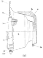
- Fig. 1 is a brushless, designed as an inner rotor Electric motor shown, which has a bell-shaped rotor 10, which has a free interior 12.
- the rotor is through the rotor bell 10a formed on its outer surface 10b a rotor laminated core 11, which is axially spaced by one of two Short-circuit rings 11a, 11b and connecting them Copper rods 11c formed cage is held together.
- a stator pack 14 is arranged to that Rotor 10 is at a radial distance, forming an annular gap a stator pack 14 is arranged.
- the stator package exists from a laminated core 14a and stator windings, the winding heads 14b, 14c protrude on both end faces of the laminated core 14a.
- the illustrated rotor bell 10a is designed in two parts, that is, it consists of an end plate 10b and a jacket 10c, which with the end plate 10b rotatably by one in one Threaded hole 10d screw 10e is screwed.
- the rotor bell can also be made in one piece.
- the gear 16 has sun gear shaft 18, which with the rotor bell 10a is coaxially and non-rotatably connected.
- This connection can either be done by a shaft journal, the one Has tooth profile on which the rotor bell with a corresponding shaped opening is shrunk, or the rotor bell is screwed onto the shaft journal.
- the Connection be made in one piece, that is, the sun gear shaft and the rotor bell are made as a common rotating part produced.
- the planetary gear also has a ring gear 20 which also forms the housing of the transmission 16.
- the sun gear shaft 18 is supported in the ring gear 20 by a ball bearing 22. Furthermore is the side of the shaft bushing pointing towards the rotor bell 10a provided with a seal 24.
- the inner ring of the ball bearing 22 is on the sun gear shaft 18th by a clamping ring 26 inserted into a groove 25 against one Level 28 set.
- the outer ring of the ball bearing 22 is on the ring gear 20 by a inserted in a groove 30 Clamping ring 32 against the front inner wall 34 of the ring gear 20 fixed.
- the sun gear 36 is rotatably seated on the sun gear shaft 18 and meshes with three planet gears 38, only one of which illustrates is.
- the planet gears 38 are through a planet gear carrier 40 held, each with a pin 42 are connected.
- the planet gears 38 mesh with one Internal toothing 44 of the ring gear 20.
- the inner end of the sun gear shaft 18 is through a bearing 46 rotatably supported against the planet carrier 40, the in turn rotatably supported by a bearing 48 against the ring gear 20 is.
- the two bearings 46 and 48 are aligned with one another aligned (see escape line F).
- the planetary ring gear 20 has an outer contour, the sections the inner contour of the rotor bell 10a follows.
- a fastening device 50 in the form of a flange for a support plate 52 for the stator 14.
- the support plate 52 for the stator 14 has an annular shape and surrounds the planetary ring gear 20 in the area thereof by the rotor bell 10a pioneering end face 54.
- the fastening device 50 is open at the edge Recess 50a of the planetary ring gear 20 in the area thereof Face 54 and several evenly along the circumference distributed threaded holes 50b formed, whereby the support plate 52nd for the stator 14 rigidly attached to the planet ring gear 20 is.
- This embodiment is also the lower half in FIG. 2 illustrated.
- the inner ring of the ball bearing 48 is on the planet carrier 40 against by a clamping ring 60 inserted in a groove 58 a stage 62 is set on the planetary ring gear 20.
- the outer Ring of the ball bearing 48 is on the planet ring gear 20 through a in a groove 64 inserted clamping ring 66 against a step 68 set in the inner wall of the planetary ring gear 20.
- the planet gear carrier 40 has an offset inwards Flange point 72 in the form of a cylindrical recess, the several coaxial threaded holes 74 for screwing with one PTO shaft (not illustrated).
Claims (2)
- Moteur électrique comprenant un rotor intérieur (10) et un stator (14) disposé radialement espacé de celui-ci, le rotor présentant un espace libre intérieur (12) dans lequel au moins une partie d'une transmission (16) formée d'un système d'engrenages planétaires comprenant un arbre de roue solaire (18), une roue à denture intérieure (20) et un porte-pignons satellites (40), dont l'arbre de roue solaire (18) présente à sa portion d'extrémité faisant saillie hors de la roue à denture intérieure (20) un dispositif de fixation pour le rotor (10), et dont la roue à denture intérieure (20) présente un dispositif de fixation pour une plaque de support (52) qui entoure annulairement la roue à denture intérieure (20) dans la zone de l'une de ses faces frontales (54) et qui tient le stator (14), dans lequel le rotor (10) est monté à rotation par l'intermédiaire de l'arbre de roue solaire (18) avec un palier (22) du côté en cloche du rotor dans la roue à denture intérieure (20), l'extrémité située à l'intérieur de l'arbre de roue solaire (18) est appuyée à rotation au moyen d'un palier (46) contre le porte-pignons satellites (40) et celui-ci est monté à rotation au moyen d'un autre palier (48) dans la roue à denture intérieure (20) et dans lequel le porte-pignons satellites (40) présente un emplacement de flasque de sortie (72) déporté vers l'intérieur.
- Moteur électrique comprenant un rotor intérieur (10) et un stator (14) disposé radialement espacé de celui-ci, le rotor présentant un espace libre intérieur (12) dans lequel au moins une partie d'une transmission (16) formée d'un système d'engrenages planétaires comprenant un arbre de roue solaire (18), une roue à denture intérieure (20) et un porte-pignons satellites (40), dont la roue à denture intérieure (20) présente un dispositif de fixation pour une plaque de support (52) qui entoure annulairement la roue à denture intérieure (20) dans la zone de l'une de ses faces frontales (54) et qui tient le stator (14), dans lequel le rotor (10) est monté à rotation par l'intermédiaire de l'arbre de roue solaire (18) qui fait corps avec lui avec un palier (22) du côté en cloche du rotor dans la roue à denture intérieure (20), l'extrémité située à l'intérieur de l'arbre de roue solaire (18) est appuyée à rotation au moyen d'un palier (46) contre le porte-pignons satellites (40) et celui-ci est monté à rotation au moyen d'un autre palier (48) dans la roue à denture intérieure (20) et dans lequel le porte-pignons satellites (40) présente un emplacement de flasque (72) déporté vers l'intérieur.
Applications Claiming Priority (3)
| Application Number | Priority Date | Filing Date | Title |
|---|---|---|---|
| DE4407714 | 1994-03-08 | ||
| DE4407714A DE4407714C1 (de) | 1994-03-08 | 1994-03-08 | Elektromotor |
| PCT/EP1995/000767 WO1995024761A1 (fr) | 1994-03-08 | 1995-03-02 | Moteur electrique |
Publications (2)
| Publication Number | Publication Date |
|---|---|
| EP0749643A1 EP0749643A1 (fr) | 1996-12-27 |
| EP0749643B1 true EP0749643B1 (fr) | 1998-07-22 |
Family
ID=6512174
Family Applications (1)
| Application Number | Title | Priority Date | Filing Date |
|---|---|---|---|
| EP95912190A Expired - Lifetime EP0749643B1 (fr) | 1994-03-08 | 1995-03-02 | Moteur electrique |
Country Status (7)
| Country | Link |
|---|---|
| US (1) | US5770904A (fr) |
| EP (1) | EP0749643B1 (fr) |
| JP (1) | JPH09510076A (fr) |
| KR (1) | KR970701941A (fr) |
| DE (2) | DE4407714C1 (fr) |
| ES (1) | ES2119409T3 (fr) |
| WO (1) | WO1995024761A1 (fr) |
Families Citing this family (15)
| Publication number | Priority date | Publication date | Assignee | Title |
|---|---|---|---|---|
| DE19531956A1 (de) * | 1995-08-30 | 1997-03-06 | Siemens Ag | Einzelradantrieb für ein elektrisch angetriebenes Fahrzeug |
| DE19827756A1 (de) * | 1998-06-23 | 1999-12-30 | Umbach Hans | Antrieb |
| DE19837487C2 (de) * | 1998-08-12 | 2002-07-18 | Lohmann & Stolterfoht Gmbh | Dichtungsanordnung |
| DE19916459A1 (de) * | 1999-04-12 | 2000-10-26 | Bosch Gmbh Robert | Starter-Generator für ein Kraftfahrzeug |
| JP3560947B2 (ja) | 2001-11-06 | 2004-09-02 | 株式会社日立製作所 | 回転電機 |
| US7131275B2 (en) * | 2002-12-06 | 2006-11-07 | Hamilton Sundstrand | Gas turbine engine system having an electric starter motor with integral clutch |
| RU2321138C1 (ru) * | 2007-01-10 | 2008-03-27 | Семен Львович Самсонович | Силовой мини-привод |
| EP2385612B1 (fr) | 2010-05-06 | 2014-07-02 | Moventas Gears Oy | Dispositif électromécanique |
| ES2415505T3 (es) | 2010-05-06 | 2013-07-25 | The Switch Drive Systems Oy | Una máquina eléctrica y un procedimiento para el montaje de ésta |
| ES2730717T3 (es) | 2010-05-06 | 2019-11-12 | The Switch Drive Systems Oy | Dispositivo electromecánico |
| DK2385611T3 (da) | 2010-05-06 | 2013-05-27 | Moventas Gears Oy | Elektromekanisk apparat |
| JP6596897B2 (ja) * | 2015-04-13 | 2019-10-30 | 日産自動車株式会社 | モータ駆動装置 |
| CN106274463B (zh) * | 2016-09-27 | 2017-08-25 | 许昌禾润机电有限公司 | 一种集成式电驱动总成 |
| EP4279307A1 (fr) | 2022-05-20 | 2023-11-22 | Tatus, Andreas | Unité d'entraînement |
| DE102022112798A1 (de) | 2022-05-20 | 2023-11-23 | Andreas Tatus | Antriebseinheit |
Family Cites Families (20)
| Publication number | Priority date | Publication date | Assignee | Title |
|---|---|---|---|---|
| AT108063B (de) * | 1926-10-30 | 1927-11-25 | Siemens Schuckertwerke Wien | Asynchronmotor mit Fremdbelüftung. |
| US2514460A (en) * | 1946-05-07 | 1950-07-11 | Jesse D Tucker | Wheel motor unit |
| FR1381593A (fr) * | 1963-11-06 | 1964-12-14 | American Radiator & Standard | Moteur électrique refroidi par un réfrigérant |
| DE2145126A1 (de) * | 1971-09-09 | 1973-03-22 | Siemens Ag | Elektrische maschine mit oelspruehkuehlung |
| DE2455567A1 (de) * | 1974-11-23 | 1976-05-26 | Ruhrkohle Ag | Kuehlwasser-mengenregelung |
| DE2538561C3 (de) * | 1975-08-29 | 1980-06-04 | Arnold 7312 Kirchheim Mueller | Induktionsmotor |
| US4274023A (en) * | 1979-05-10 | 1981-06-16 | Lamprey Donald F | Compact variable speed drive for electric motor |
| JPS58116044A (ja) * | 1981-12-28 | 1983-07-11 | Toshiba Corp | 回転電機巻線冷却水循環装置 |
| JPS60162434A (ja) * | 1984-02-01 | 1985-08-24 | Ebara Corp | 液冷回転電機 |
| DE3444420A1 (de) * | 1984-12-04 | 1986-06-05 | Arnold 7312 Kirchheim Müller | Vorrichtung zur erzeugung von schwenkbewegungen |
| DE8513219U1 (de) * | 1985-05-04 | 1986-05-22 | Heidelberger Druckmaschinen Ag, 6900 Heidelberg | Elektromotor mit damit gekoppeltem mechanischem Getriebe |
| US5019733A (en) * | 1987-09-25 | 1991-05-28 | Honda Giken Kogyo Kabushiki Kaisha | AC generator |
| FR2664106A1 (fr) * | 1990-06-29 | 1992-01-03 | Peugeot | Moteur electrique de traction a courant continu pour vehicule automobile. |
| DE4120262B4 (de) * | 1990-11-20 | 2007-03-22 | Aisin AW Co., Ltd., Anjo | Radmotor mit einem Untersetzungsgetriebe |
| JP2896225B2 (ja) * | 1990-11-20 | 1999-05-31 | アイシン・エィ・ダブリュ株式会社 | ホイールモータの潤滑装置 |
| JP2991802B2 (ja) * | 1991-04-26 | 1999-12-20 | 本田技研工業株式会社 | 変速機付電動機 |
| DE4213132A1 (de) * | 1991-05-10 | 1992-11-12 | Audi Ag | Elektrisch antreibbares kraftfahrzeug |
| JPH05300692A (ja) * | 1992-04-22 | 1993-11-12 | Mitsubishi Electric Corp | 車両の発電兼始動装置 |
| DE4311957A1 (de) * | 1993-04-10 | 1994-10-20 | Ecoform Umformtechnik Gmbh | Verfahren und Vorrichtung zum definierten Abdünnen eines Schmiermittelrestfilmes auf strangförmigem metallischem Umformgut |
| DE4319576A1 (de) * | 1993-06-14 | 1994-12-15 | Bilstein August Gmbh Co Kg | Elektromotorischer Verstellantrieb |
-
1994
- 1994-03-08 DE DE4407714A patent/DE4407714C1/de not_active Expired - Fee Related
-
1995
- 1995-03-02 JP JP7523206A patent/JPH09510076A/ja active Pending
- 1995-03-02 KR KR1019960704943A patent/KR970701941A/ko not_active Application Discontinuation
- 1995-03-02 ES ES95912190T patent/ES2119409T3/es not_active Expired - Lifetime
- 1995-03-02 EP EP95912190A patent/EP0749643B1/fr not_active Expired - Lifetime
- 1995-03-02 US US08/699,507 patent/US5770904A/en not_active Expired - Lifetime
- 1995-03-02 DE DE59502898T patent/DE59502898D1/de not_active Expired - Lifetime
- 1995-03-02 WO PCT/EP1995/000767 patent/WO1995024761A1/fr active IP Right Grant
Also Published As
| Publication number | Publication date |
|---|---|
| JPH09510076A (ja) | 1997-10-07 |
| KR970701941A (ko) | 1997-04-12 |
| DE59502898D1 (de) | 1998-08-27 |
| DE4407714C1 (de) | 1995-07-06 |
| ES2119409T3 (es) | 1998-10-01 |
| US5770904A (en) | 1998-06-23 |
| WO1995024761A1 (fr) | 1995-09-14 |
| EP0749643A1 (fr) | 1996-12-27 |
Similar Documents
| Publication | Publication Date | Title |
|---|---|---|
| EP0749643B1 (fr) | Moteur electrique | |
| DE4323599C1 (de) | Antriebseinheit | |
| DE4120262B4 (de) | Radmotor mit einem Untersetzungsgetriebe | |
| DE19945345A1 (de) | Radantrieb zum Antrieb eines Fahrzeugrades | |
| DE3240345A1 (de) | Seiltrommelantrieb | |
| DE2842076A1 (de) | Einzelradantrieb fuer fahrzeuge | |
| DE19748201C1 (de) | Nabenantriebsvorrichtung | |
| DE102018205473A1 (de) | Lagerung für ein Hybridmodul | |
| DE4102932C2 (de) | Getriebemotor | |
| CH648102A5 (de) | Abzweiggetriebe fuer einen schiffsantrieb. | |
| EP0601433B1 (fr) | Equipement moteur | |
| EP0538743A2 (fr) | Groupe de moteur et engrenage planétaire entraîné par moteur électrique | |
| DE19530155A1 (de) | Einzelachsantrieb elektrischer Triebfahrzeuge | |
| EP0542171B1 (fr) | Unité motorisée pour engins de traction ferroviaires | |
| WO2018054599A1 (fr) | Unité d'entraînement électrique munie d'une douille de refroidissement | |
| DE10220552A1 (de) | Antriebsvorrichtung für einen gleichsinnig drehenden Mehrwellenextruder | |
| EP0716914A1 (fr) | Transmission pour extrudeuse à deux vis | |
| DE102005041750B4 (de) | Baukastensystem für Stirnradantriebe unterschiedlicher Leistung für Flurförderzeuge | |
| DE3605703C2 (fr) | ||
| DE19539984C2 (de) | Antrieb für ein Druckwerk | |
| DE102019205757A1 (de) | Getriebeanordnung für ein Kraftfahrzeug und Verfahren zur Montage einer Getriebeanordnung | |
| WO2019154682A1 (fr) | Unité d'entraînement électrique pour un véhicule à moteur | |
| DE102018009398A1 (de) | Antriebseinrichtung für ein Kraftfahrzeug mit einer Antriebseinheit | |
| EP0285683B1 (fr) | Système de propulsion pour bateaux | |
| DE10035028A1 (de) | Kraftfahrzeug-Antriebsstrang |
Legal Events
| Date | Code | Title | Description |
|---|---|---|---|
| PUAI | Public reference made under article 153(3) epc to a published international application that has entered the european phase |
Free format text: ORIGINAL CODE: 0009012 |
|
| 17P | Request for examination filed |
Effective date: 19960902 |
|
| AK | Designated contracting states |
Kind code of ref document: A1 Designated state(s): CH DE ES FR GB IT LI SE |
|
| GRAG | Despatch of communication of intention to grant |
Free format text: ORIGINAL CODE: EPIDOS AGRA |
|
| 17Q | First examination report despatched |
Effective date: 19971006 |
|
| GRAG | Despatch of communication of intention to grant |
Free format text: ORIGINAL CODE: EPIDOS AGRA |
|
| GRAH | Despatch of communication of intention to grant a patent |
Free format text: ORIGINAL CODE: EPIDOS IGRA |
|
| GRAH | Despatch of communication of intention to grant a patent |
Free format text: ORIGINAL CODE: EPIDOS IGRA |
|
| GRAA | (expected) grant |
Free format text: ORIGINAL CODE: 0009210 |
|
| RAP1 | Party data changed (applicant data changed or rights of an application transferred) |
Owner name: GRUENDL UND HOFFMANN GMBH GESELLSCHAFT FUER ELEKTR |
|
| AK | Designated contracting states |
Kind code of ref document: B1 Designated state(s): CH DE ES FR GB IT LI SE |
|
| REG | Reference to a national code |
Ref country code: CH Ref legal event code: EP |
|
| GBT | Gb: translation of ep patent filed (gb section 77(6)(a)/1977) |
Effective date: 19980723 |
|
| REF | Corresponds to: |
Ref document number: 59502898 Country of ref document: DE Date of ref document: 19980827 |
|
| REG | Reference to a national code |
Ref country code: ES Ref legal event code: FG2A Ref document number: 2119409 Country of ref document: ES Kind code of ref document: T3 |
|
| ET | Fr: translation filed | ||
| PLBE | No opposition filed within time limit |
Free format text: ORIGINAL CODE: 0009261 |
|
| STAA | Information on the status of an ep patent application or granted ep patent |
Free format text: STATUS: NO OPPOSITION FILED WITHIN TIME LIMIT |
|
| 26N | No opposition filed | ||
| PGFP | Annual fee paid to national office [announced via postgrant information from national office to epo] |
Ref country code: ES Payment date: 20000427 Year of fee payment: 6 |
|
| PGFP | Annual fee paid to national office [announced via postgrant information from national office to epo] |
Ref country code: SE Payment date: 20000523 Year of fee payment: 6 Ref country code: CH Payment date: 20000523 Year of fee payment: 6 |
|
| PG25 | Lapsed in a contracting state [announced via postgrant information from national office to epo] |
Ref country code: SE Free format text: LAPSE BECAUSE OF NON-PAYMENT OF DUE FEES Effective date: 20010303 Ref country code: ES Free format text: LAPSE BECAUSE OF NON-PAYMENT OF DUE FEES Effective date: 20010303 |
|
| PG25 | Lapsed in a contracting state [announced via postgrant information from national office to epo] |
Ref country code: LI Free format text: LAPSE BECAUSE OF NON-PAYMENT OF DUE FEES Effective date: 20010331 Ref country code: CH Free format text: LAPSE BECAUSE OF NON-PAYMENT OF DUE FEES Effective date: 20010331 |
|
| EUG | Se: european patent has lapsed |
Ref document number: 95912190.6 |
|
| REG | Reference to a national code |
Ref country code: CH Ref legal event code: PL |
|
| REG | Reference to a national code |
Ref country code: GB Ref legal event code: IF02 |
|
| REG | Reference to a national code |
Ref country code: ES Ref legal event code: FD2A Effective date: 20030203 |
|
| PGFP | Annual fee paid to national office [announced via postgrant information from national office to epo] |
Ref country code: GB Payment date: 20040303 Year of fee payment: 10 |
|
| PGFP | Annual fee paid to national office [announced via postgrant information from national office to epo] |
Ref country code: FR Payment date: 20040310 Year of fee payment: 10 |
|
| PG25 | Lapsed in a contracting state [announced via postgrant information from national office to epo] |
Ref country code: IT Free format text: LAPSE BECAUSE OF NON-PAYMENT OF DUE FEES;WARNING: LAPSES OF ITALIAN PATENTS WITH EFFECTIVE DATE BEFORE 2007 MAY HAVE OCCURRED AT ANY TIME BEFORE 2007. THE CORRECT EFFECTIVE DATE MAY BE DIFFERENT FROM THE ONE RECORDED. Effective date: 20050302 Ref country code: GB Free format text: LAPSE BECAUSE OF NON-PAYMENT OF DUE FEES Effective date: 20050302 |
|
| GBPC | Gb: european patent ceased through non-payment of renewal fee |
Effective date: 20050302 |
|
| PG25 | Lapsed in a contracting state [announced via postgrant information from national office to epo] |
Ref country code: FR Free format text: LAPSE BECAUSE OF NON-PAYMENT OF DUE FEES Effective date: 20051130 |
|
| REG | Reference to a national code |
Ref country code: FR Ref legal event code: ST Effective date: 20051130 |
|
| PGFP | Annual fee paid to national office [announced via postgrant information from national office to epo] |
Ref country code: DE Payment date: 20140331 Year of fee payment: 20 |
|
| REG | Reference to a national code |
Ref country code: DE Ref legal event code: R071 Ref document number: 59502898 Country of ref document: DE |