EP0748683B1 - Procédé de fabrication d'un panneau avec un cadre en matière plastique - Google Patents
Procédé de fabrication d'un panneau avec un cadre en matière plastique Download PDFInfo
- Publication number
- EP0748683B1 EP0748683B1 EP96109536A EP96109536A EP0748683B1 EP 0748683 B1 EP0748683 B1 EP 0748683B1 EP 96109536 A EP96109536 A EP 96109536A EP 96109536 A EP96109536 A EP 96109536A EP 0748683 B1 EP0748683 B1 EP 0748683B1
- Authority
- EP
- European Patent Office
- Prior art keywords
- panel
- shaped product
- pressing member
- frame
- peripheral portion
- Prior art date
- Legal status (The legal status is an assumption and is not a legal conclusion. Google has not performed a legal analysis and makes no representation as to the accuracy of the status listed.)
- Expired - Lifetime
Links
Images


Classifications
-
- B—PERFORMING OPERATIONS; TRANSPORTING
- B60—VEHICLES IN GENERAL
- B60J—WINDOWS, WINDSCREENS, NON-FIXED ROOFS, DOORS, OR SIMILAR DEVICES FOR VEHICLES; REMOVABLE EXTERNAL PROTECTIVE COVERINGS SPECIALLY ADAPTED FOR VEHICLES
- B60J10/00—Sealing arrangements
- B60J10/70—Sealing arrangements specially adapted for windows or windscreens
-
- B—PERFORMING OPERATIONS; TRANSPORTING
- B29—WORKING OF PLASTICS; WORKING OF SUBSTANCES IN A PLASTIC STATE IN GENERAL
- B29C—SHAPING OR JOINING OF PLASTICS; SHAPING OF MATERIAL IN A PLASTIC STATE, NOT OTHERWISE PROVIDED FOR; AFTER-TREATMENT OF THE SHAPED PRODUCTS, e.g. REPAIRING
- B29C48/00—Extrusion moulding, i.e. expressing the moulding material through a die or nozzle which imparts the desired form; Apparatus therefor
- B29C48/001—Combinations of extrusion moulding with other shaping operations
-
- B—PERFORMING OPERATIONS; TRANSPORTING
- B29—WORKING OF PLASTICS; WORKING OF SUBSTANCES IN A PLASTIC STATE IN GENERAL
- B29C—SHAPING OR JOINING OF PLASTICS; SHAPING OF MATERIAL IN A PLASTIC STATE, NOT OTHERWISE PROVIDED FOR; AFTER-TREATMENT OF THE SHAPED PRODUCTS, e.g. REPAIRING
- B29C48/00—Extrusion moulding, i.e. expressing the moulding material through a die or nozzle which imparts the desired form; Apparatus therefor
- B29C48/03—Extrusion moulding, i.e. expressing the moulding material through a die or nozzle which imparts the desired form; Apparatus therefor characterised by the shape of the extruded material at extrusion
- B29C48/12—Articles with an irregular circumference when viewed in cross-section, e.g. window profiles
-
- B—PERFORMING OPERATIONS; TRANSPORTING
- B29—WORKING OF PLASTICS; WORKING OF SUBSTANCES IN A PLASTIC STATE IN GENERAL
- B29C—SHAPING OR JOINING OF PLASTICS; SHAPING OF MATERIAL IN A PLASTIC STATE, NOT OTHERWISE PROVIDED FOR; AFTER-TREATMENT OF THE SHAPED PRODUCTS, e.g. REPAIRING
- B29C48/00—Extrusion moulding, i.e. expressing the moulding material through a die or nozzle which imparts the desired form; Apparatus therefor
- B29C48/14—Extrusion moulding, i.e. expressing the moulding material through a die or nozzle which imparts the desired form; Apparatus therefor characterised by the particular extruding conditions, e.g. in a modified atmosphere or by using vibration
- B29C48/147—Extrusion moulding, i.e. expressing the moulding material through a die or nozzle which imparts the desired form; Apparatus therefor characterised by the particular extruding conditions, e.g. in a modified atmosphere or by using vibration after the die nozzle
- B29C48/1472—Extrusion moulding, i.e. expressing the moulding material through a die or nozzle which imparts the desired form; Apparatus therefor characterised by the particular extruding conditions, e.g. in a modified atmosphere or by using vibration after the die nozzle at the die nozzle exit zone
-
- B—PERFORMING OPERATIONS; TRANSPORTING
- B29—WORKING OF PLASTICS; WORKING OF SUBSTANCES IN A PLASTIC STATE IN GENERAL
- B29C—SHAPING OR JOINING OF PLASTICS; SHAPING OF MATERIAL IN A PLASTIC STATE, NOT OTHERWISE PROVIDED FOR; AFTER-TREATMENT OF THE SHAPED PRODUCTS, e.g. REPAIRING
- B29C48/00—Extrusion moulding, i.e. expressing the moulding material through a die or nozzle which imparts the desired form; Apparatus therefor
- B29C48/15—Extrusion moulding, i.e. expressing the moulding material through a die or nozzle which imparts the desired form; Apparatus therefor incorporating preformed parts or layers, e.g. extrusion moulding around inserts
- B29C48/154—Coating solid articles, i.e. non-hollow articles
- B29C48/155—Partial coating thereof
-
- B—PERFORMING OPERATIONS; TRANSPORTING
- B29—WORKING OF PLASTICS; WORKING OF SUBSTANCES IN A PLASTIC STATE IN GENERAL
- B29C—SHAPING OR JOINING OF PLASTICS; SHAPING OF MATERIAL IN A PLASTIC STATE, NOT OTHERWISE PROVIDED FOR; AFTER-TREATMENT OF THE SHAPED PRODUCTS, e.g. REPAIRING
- B29C63/00—Lining or sheathing, i.e. applying preformed layers or sheathings of plastics; Apparatus therefor
- B29C63/0026—Lining or sheathing, i.e. applying preformed layers or sheathings of plastics; Apparatus therefor an edge face with strip material, e.g. a panel edge
- B29C63/0034—Lining or sheathing, i.e. applying preformed layers or sheathings of plastics; Apparatus therefor an edge face with strip material, e.g. a panel edge the strip material being folded
- B29C63/0039—Lining or sheathing, i.e. applying preformed layers or sheathings of plastics; Apparatus therefor an edge face with strip material, e.g. a panel edge the strip material being folded continuously
-
- B—PERFORMING OPERATIONS; TRANSPORTING
- B60—VEHICLES IN GENERAL
- B60J—WINDOWS, WINDSCREENS, NON-FIXED ROOFS, DOORS, OR SIMILAR DEVICES FOR VEHICLES; REMOVABLE EXTERNAL PROTECTIVE COVERINGS SPECIALLY ADAPTED FOR VEHICLES
- B60J10/00—Sealing arrangements
- B60J10/45—Assembling sealing arrangements with vehicle parts
-
- B—PERFORMING OPERATIONS; TRANSPORTING
- B29—WORKING OF PLASTICS; WORKING OF SUBSTANCES IN A PLASTIC STATE IN GENERAL
- B29C—SHAPING OR JOINING OF PLASTICS; SHAPING OF MATERIAL IN A PLASTIC STATE, NOT OTHERWISE PROVIDED FOR; AFTER-TREATMENT OF THE SHAPED PRODUCTS, e.g. REPAIRING
- B29C35/00—Heating, cooling or curing, e.g. crosslinking or vulcanising; Apparatus therefor
- B29C35/16—Cooling
- B29C2035/1658—Cooling using gas
-
- B—PERFORMING OPERATIONS; TRANSPORTING
- B29—WORKING OF PLASTICS; WORKING OF SUBSTANCES IN A PLASTIC STATE IN GENERAL
- B29C—SHAPING OR JOINING OF PLASTICS; SHAPING OF MATERIAL IN A PLASTIC STATE, NOT OTHERWISE PROVIDED FOR; AFTER-TREATMENT OF THE SHAPED PRODUCTS, e.g. REPAIRING
- B29C2791/00—Shaping characteristics in general
- B29C2791/004—Shaping under special conditions
- B29C2791/007—Using fluid under pressure
-
- B—PERFORMING OPERATIONS; TRANSPORTING
- B29—WORKING OF PLASTICS; WORKING OF SUBSTANCES IN A PLASTIC STATE IN GENERAL
- B29C—SHAPING OR JOINING OF PLASTICS; SHAPING OF MATERIAL IN A PLASTIC STATE, NOT OTHERWISE PROVIDED FOR; AFTER-TREATMENT OF THE SHAPED PRODUCTS, e.g. REPAIRING
- B29C35/00—Heating, cooling or curing, e.g. crosslinking or vulcanising; Apparatus therefor
- B29C35/02—Heating or curing, e.g. crosslinking or vulcanizing during moulding, e.g. in a mould
- B29C35/04—Heating or curing, e.g. crosslinking or vulcanizing during moulding, e.g. in a mould using liquids, gas or steam
- B29C35/045—Heating or curing, e.g. crosslinking or vulcanizing during moulding, e.g. in a mould using liquids, gas or steam using gas or flames
-
- B—PERFORMING OPERATIONS; TRANSPORTING
- B29—WORKING OF PLASTICS; WORKING OF SUBSTANCES IN A PLASTIC STATE IN GENERAL
- B29K—INDEXING SCHEME ASSOCIATED WITH SUBCLASSES B29B, B29C OR B29D, RELATING TO MOULDING MATERIALS OR TO MATERIALS FOR MOULDS, REINFORCEMENTS, FILLERS OR PREFORMED PARTS, e.g. INSERTS
- B29K2027/00—Use of polyvinylhalogenides or derivatives thereof as moulding material
- B29K2027/06—PVC, i.e. polyvinylchloride
-
- E—FIXED CONSTRUCTIONS
- E06—DOORS, WINDOWS, SHUTTERS, OR ROLLER BLINDS IN GENERAL; LADDERS
- E06B—FIXED OR MOVABLE CLOSURES FOR OPENINGS IN BUILDINGS, VEHICLES, FENCES OR LIKE ENCLOSURES IN GENERAL, e.g. DOORS, WINDOWS, BLINDS, GATES
- E06B3/00—Window sashes, door leaves, or like elements for closing wall or like openings; Layout of fixed or moving closures, e.g. windows in wall or like openings; Features of rigidly-mounted outer frames relating to the mounting of wing frames
- E06B3/66—Units comprising two or more parallel glass or like panes permanently secured together
- E06B3/673—Assembling the units
- E06B2003/67395—Non-planar units or of curvilinear outline, e.g. for vehicles
Definitions
- the present invention relates to a method for preparing a panel with a resinous frame according to the precharacterising part of claim 1.
- a panel with a resinous frame is suitable as a windowpane for vehicles and buildings.
- a method of this type is known from e.g. JP-A-57-158 479.
- a windowpane for vehicles and buildings has usually had a resinous frame such as a molded member or a gasket of synthetic resin attached in a space between a panel such as a glass sheet or plastic sheet and an opening with the panel fitted therein, thereby improving ornamentality and sealing feature.
- a resinous frame such as a molded member or a gasket of synthetic resin attached in a space between a panel such as a glass sheet or plastic sheet and an opening with the panel fitted therein, thereby improving ornamentality and sealing feature.
- the encapsulation method has advantages of minimizing labor on shaping and of giving a high degree of dimensional accuracy to a product because the panel is sandwiched between stiff mold halves made of metal and so on, the synthetic resinous material or its raw material is injected into the cavity defined by the peripheral portion of the panel and an inner surface of the mold.
- the method creates a problem wherein when the panel is a glass sheet, the glass sheet is very fragile on clamping because of in particular a warp or insufficient bending working accuracy thereof.
- JP-A-57158479 there is disclosed a method wherein a pressing jig which is constituted by rollers and so on makes a resinous frame fit on a peripheral portion of a panel and presses it against the panel just after the resinous frame has been extruded.
- This method can prevent vibration due to driving an extruder or a glass sheet from being reflected on a surface of the panel, hardly being susceptible to poor appearance in comparison with the method disclosed in U.S.P, 5,057,265.
- the peripheral size of a finished glass sheet with a frame which is prepared in accordance with the method described in JP-A-57158479 is obliged to comply with the outer size of the glass sheet because the frame is pressed against the glass sheet by the pressing jig such as rollers.
- Most glass sheet for a vehicle are usually subjected to a bending process, the glass sheet are subject to deviations in the peripheral size on bending.
- the encapsulation method can shape the resin frame so as to absorb variations in the peripheral size while the method according to JP-A-57158479 is difficult to absorb those variations for the reason stated above.
- JP-A-57158479 requires that the frame have solidified to a certain extent before being fitted on the glass sheet because the pressing is carried out by the rollers.
- US 3,239,402 discloses a method for applying a thermoplastic ribbon to at least one marginal edge of a continuous moving strip like a blank.
- the thermoplastic ribbon is extruded and then applied to the edge of the moving strip by a blower system.
- This method does not use any pressing member having a predetermined shape to press a resinous material onto a panel so that this method can only be used for the application of flat ribbons.
- a method for preparing a panel with a resinous frame wherein the resinous frame is unified to at least one surface of the panel at a peripheral portion thereof comprises extruding a resinous material for the frame in a predetermined shape from a resin shaping die to form a shaped product, and unifying the shaped product to at least one surface of a panel at a peripheral portion thereof; wherein a pressing member is arranged at a position apart from the shaping die at a predetermined distance, the pressing member having a hollow portion formed therein to substantially conform to an outer shape of the frame in section; the shaped product extruded from the die is advanced through the hollow portion; the peripheral portion of the panel is inserted into a panel inserting portion of the pressing member to arrange the pressing member at the peripheral portion of the panel; and the shaped product is unified to the peripheral portion of the panel by pressing the shaped product against the panel while relatively moving the pressing member with respect to the panel and along the peripheral portion thereof.
- FIG. 1 there is shown a schematic perspective view showing an embodiment of the method for preparing a panel 22 with a resinous frame 17 according to the present invention.
- a shaping die 14 which is attached to the leading edge of an extruder 12 extrudes a resinous material for a frame to form a shaped product 16 for the frame 17 in a predetermined shape.
- the shaped product 16 is pulled by a pulling device, and the shaped product 16 is located in a pressing member 20 to pass through a hollow portion 21 in the pressing member 20.
- a panel 22 is sucked and held by an operating robot 24.
- the panel 22 has a peripheral portion put into an inserting portion 15 of the pressing member 20, and the panel 22 is moved so that the pressing member 20 relatively moves with respect to the panel 22 and along the peripheral portion thereof.
- the shaped product 16 passes through the hollow portion 21 in the pressing member 20 to be unified to the panel 22.
- the shaped product 16 has not solidified in a sufficient manner when the shaped product 16 is passing through the hollow portion 21 in the pressing member 20, there is a possibility that poor appearance is given to a surface of the shaped product 16 (i.e. a contact portion with an inner wall of the pressing member) by the pressing member 20. In order to cope with this problem, it is necessary that the shaped product 16 has had an outermost portion solidified to a certain extent on arrival at the pressing member 20 so as to avoid surface irregularities or deformation in shape.
- the distance between the shaping die and the pressing member or another factor depending on the temperature, the viscosity or the like in the extruded material for the purpose. If a connection portion of the shaped product with the panel has solidified, the bonding force between the shaped product and the panel becomes insufficient. For these reasons, it is necessary that only the outermost portion of the shaped product has solidified, but that the connection portion of the shaped product with the panel has not solidified. Therefore, the outermost portion of the shaped product which has been extruded is quenched before the shaped product reaches the pressing member (not shown in Fig. 1).
- the resinous material is of a thermoplastic resinous material
- blowing means may be arranged between the shaping die 14 and the pressing member 20 or at an inlet of the pressing member 20 as long as the surface of the shaped product 16 can be cooled to the extent that the pressing member does not make the appearance of the shaped product 16 poor.
- the temperature of such a cooling fluid blown on the shaped product 16 ranges from about -10°C to about 80°C.
- the surface of the shaped product 16 By cooling the surface of the shaped product 16 to a temperature which is lower than the temperature of the connection portion of the shaped product 16 with the panel 22, it is possible to obtain the bonding force between the shaped product 16 and the panel 22 in a sufficient manner without degrading the appearance of a finished frame 17.
- a thermoplastic resin in particular a polyvinyl chloride resin
- the temperature of the material on extrusion ranges from about 150°C to about 190°C. It is possible to prepare the panel 22 with the frame 17 at good producibility by cooling the surface of the shaped product 16 from a temperature in such range to not higher than 150°C, in particular not higher than 130°C.
- the shaped product 16 is quenched just after the shaped product 16 has been unified to the panel 22 (see a member 40 in Figure 5).
- the shaped product 16 may be deformed due to thermal shrinkage if the shaped product 16 is cooled only by self-cooling.
- the frame 17 has a lip (17C in the drawings)
- remarkable deformation is likely to appear at the lip 17C so that the lip 17C becomes thin or bends up.
- Such deformation can be avoided by forcibly cooling and solidifying the shaped product 16 before the deformation occurs.
- such remarkable deformation is likely to appear at a portion (17A) where the shaped product 16 is unified to a corner of the panel 22.
- the embodiment has such an arrangement that when the panel corner arrives at cooling air blowing means 40, cooling air 41 is blown on the corner.
- FIG 2 there is shown a schematic sectional view showing an example of the primer treatment.
- a primer applying jig 26 which includes a pair of rollers 30 are arranged at a suitable position upstream of the pressing member 20 with respect to the relative moving direction of the panel 22 to the pressing member 20.
- primer can be applied to the peripheral portion of the panel 22 to be unified with the frame, moving the panel 22.
- an arrow indicates the direction of the relative movement of the panel 22 with respect to the pressing member 20.
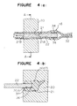
- FIG 3 there is shown a schematic perspective view showing how the members are inserted one another at the pressing member 20 and its vicinities in accordance with an example of the present invention.
- Figures 4(a) and (b) there are shown a schematic vertical sectional view showing how the members are inserted one another at the pressing member 20 and its vicinities in accordance with the example, and a sectional view along line A-A.
- the hollow portion 21 in the pressing member 20 has a cross section substantially conformed to an outer shape of the frame 17 in section at the advancing side of the shaped product 16 (at a downstream side 21B in the relative movement of the pressing member with respect to the panel).
- the shaped product 16 moves through the hollow portion 21 so as to contact with the inner wall of the pressing member 20.
- An inlet 21A of the pressing member which is located at the opposite side in the advancing direction may be formed so as to have a larger cross section than the outer shape of the frame 17 in section. The relative movement of the pressing member 20 and the panel 22 allow the frame 17 to be unified to the entire circumference or a part of the peripheral portion of the panel 22 which is inserted into the inserting portion 15 of the pressing member 20.
- the extruded shaped product 16 has such a cross-sectional shape that the shaped product has a biting portion 32 to the panel 22 (the connection portion with the panel) tapered toward an opening.
- the frame 17 is unified onto both surfaces of the panel 22 like the embodiment, it is recommendable that the extruded shaped product 16 has such a cross-sectional shape because the panel 22 and the shaped product 16 can be firmly bonded.
- a pair of slit plates 34, 34 which can expand the opening of the biting portion 32 may be provided at the upstream side of the pressing member 20 with respect to the relative movement of the pressing member 20 to the panel 22 to make the shaped product 16 smoothly bite the panel 22.
- the slit plates 34 and 34 may be heated to intensively heat the biting portion 32 of the shaped product 16.
- the slit plates 34 have a heating element and so on arranged therein to heat the slit plates 34. It is preferable that the temperature of the slit plates 34 is set to range from about 100°C to about 150°C. Such an arrangement can further improve the bonding force between the shaped product 16 and the panel 22.
- the relative movement can be realized under accurate point to point control by having taught the required movement to an operating robot 24 so that the pressing member 20 relatively moves with respect to the panel 22 and along the peripheral portion thereof.
- the slit plates 34 may be arranged in the pressing member 20. In such a case, the panel 22 is bitten into the shaped product 16 in the pressing member 20 to be unified with the shaped product 16.
- the panel 22 with the frame 17 When the panel 22 is used for a vehicle window, the panel 22 with the frame 17 is fitted into a window opening of the vehicle.
- the state in which the panel 22 with the frame 17 is fitted into the window opening depends on the peripheral (lip) position of a frame portion of the panel 22 with the frame 17. It means that when the biting portion of the frame 17 into which the panel extends to an end surface of the panel 22, the peripheral position of the frame portion of the panel 22 with the frame 17 varies on the outer size of the panel 22. If the outer size of the panel 22 involves an error with respect to a preset size, the state in which the panel 22 with the frame 17 is fitted into the window opening might be unacceptable.
- An error in the outer size of the panel 22 itself can be absorbed by having taught movement of the panel 22 to the operating robot 24 so that a space 36 is formed between the bottom of the biting portion 32 with the panel 22 bit in the shaped product 16 and an end surface of the panel 22 preset to have a predetermined size, as shown in Figure 4(b). If the outer size of the panel 22 is larger than the predetermined size (designed size), the space 36 becomes smaller or disappears. In the reverse case, only an increase in the space 36 occurs, and the panel 22 with the frame 17 has the outer size itself taken such a predetermined size to be fit in the window opening in a good manner at any time. This solution is effective in particular to mass-produce panels 22 with a frame 17.
- the operating robot 24 (control means therefor) is made to memorize designed size of the panel 22 in advance and to grasp a planned position of the peripheral portion of the panel 22 based on the designed size.
- the peripheral portion of the panel 22 is relatively moved with respect to the pressing member 20 so that the planned position of the peripheral portion of the panel 22 constantly moves at the predetermined position with respect to the pressing member 20.
- the outer size of panels 22 which have had a frame 17 unified thereto can be constantly kept constant even if the extent to which the frames 17 bite the panels 22 varies according to the respective panels 22.
- the present invention offers an advantage in that if such an error is caused, the state in which the panel 22 with the frame 17 is fitted into the window opening can be made fine only by modifying the control for the operating robot 24 according to the error.
- the control of the relative movement according to the present invention can adjust the outer size of the panel 22 with the frame 17 to improve the state with the panel 22 fitted in the window opening even after mass production of vehicles has started.
- a resinous material for the frame is extruded from the shaping die 14 mounted to the leading edge of the extruder 12.
- the shaped product 16 for the frame 17 thus extruded in a predetermined shape is held by a chuck 19 of the pulling device 18.
- the shaped product 16 is made to advance toward the hollow portion 21 in the pressing member 20, the shaped product 16 has the outermost portion solidified by blowing cooling air onto the shaped product 16 from the blowing means 44, and the shaped product 16 is introduced into the hollow portion 21 (see Figure 5(a)).
- the operating robot 24 is holding the panel 22 at a stand-by position (not shown).
- the operating robot 24 is activated to move the panel 22 so that the panel 22 has the peripheral portion inserted into the panel inserting portion 15 of the pressing member 20 (see Figure 5(b)). It is preferable that an excess portion of the extruded shaped product 16 is cut off by a cutter 46 at that time. The shaped product 16 is pulled by the pulling device 18 before the shaped product 16 is made to bite the panel 22.
- the shaped product 16 is unified to the peripheral portion of the panel 22 by moving the panel 22 so that the pressing member 20 relatively moves with respect to the panel 22 and along the peripheral portion thereof. Finally, the shaped product 16 is cut off by the cutter 46 to separate the unified portion of the shaped product 16 from a portion of the shaped product 16 extending from the shaping die 14 (see Figure 5(c)). In that manner, the frame 17 can be unified to the peripheral portion of the panel 22. Furthermore, the remaining shaped product 16 can be advanced by the pulling device 18 to move onto a process to unify a frame 17 to the next panel 22.
- a guide member may be arranged between the shaping die 14 and the pressing member 20 as an alternative to the pulling device 18.
- the shaped product 16 can advance along the guide member to smoothly introduce the shaped product 16 into the hollow portion 21 in the pressing member 20.
- use of pulling device 18 is recommendable, taking into account that use of the pulling device 18 can cope with various conditions such as a case wherein a certain distance must be ensured between the shaping die 14 and the pressing member 20 to adjust a temperature on the surface of the shaped product 16.
- a pulling device 18' which is constructed as shown in Figure 6 is used as an alternative to the pulling device 18 stated earlier.
- the pulley device 18' with rollers as shown is arranged at the side of the pressing member 20 opposite to the shaping die 14.
- a cutter 46' can be provided after the pulling device 18' to eliminate the need for provision of a rail above the producing apparatus unlike the case shown in Figure 5, making the entire apparatus compact.
- the panel 22 is moved to obtain the relative movement of the pressing member 20 with respect to the peripheral portion of the panel 22, the pressing member 20 itself may be moved, or the movement of the panel 22 and the pressing member 20 may be controlled to obtain the relative movement. It is enough that the panel 22 and the pressing member 20 carry out the relative movement along the peripheral portion of the panel 22. Since moving the pressing member 20 requires to move the shaping die 14 or the pulling device 18 as well, moving only the panel 22 is preferable.
- the speed at which the panel 22 and the pressing member 20 relatively move has no limitation.
- the speed may be constant, or the speed may be increased or decreased at e.g. a corner of the panel 22.
- the throughput of the resinous material may be changed according to the change of the speed.
- the error with respect to the predetermined size of the panel 22 has been already discussed.
- the error was related to the outer size. If the panel 22 is formed in a bending shape, an error in curvature as well as the error in outer shape would possibly occur.
- the error in curvature can be dealt with by e.g. the following measures: the panel 22 has an upper portion moved with respect to the pressing member 20 in advance so that the panel 22 has an upper surface pressed against an upper surface of the inserting portion 21 in the pressing member 20 to a certain extent. Even if the panel 22 has an error in curvature, the measures can absorb the error in curvature by making the upper surface of the panel 22 relatively move so as to constantly contact with the upper surface of the inserting portion 21 in the pressing member 20. In the measures, it is preferable that fluorocarbon resin coating is applied to the contacting surface of the inserting portion 21 with the panel 22.
- the example just above mentioned is called upper surface follow. Lower surface follow is also applicable, and it can offer similar effects.
- the panel 22 is sometimes likely to have a corner deformed in comparison with a linear portion of the panel 22, which is noticeable in the case of the panel 22 having large curvature at the corner.
- it is recommendable to release the pressing force to the shaped product 16 by the pressing member at only a portion which is likely to be deformed (e.g. the corner).
- such an operation can be carried out by e.g. open the pressing member 20 in upper and lower directions or releasing pushing means (pushing by e.g. an air cylinder through e.g. a roller) on the pressing member 20 at the corner of the panel 22.
- the shaped product 16 may be quenched by contacting the shaped product 16 with a cooling member which has a groove formed to substantially conform with the shape of the shaped product 16.
- panel 22 used in the present invention various types of panels used as a windowpane for a vehicle or building, such as a single glass sheet, laminated glass, laminated glass with a transparent synthetic resin film laminated on a glass sheet, and pair glass, are selectively adopted according to applications.
- Those types of glass sheets may be subjected to bending process, tempering treatment, function coating treatment or the like.
- a transparent organic resinous sheet called organic glass, or a glass sheet with the organic glass laminated thereon can be adopted.
- Examples of the resinous material for the frame 17 used in the present invention include materials usable in extrusion, such as a thermoplastic resin, and a thermoset or moisture setting resin which are heated and melted for use.
- examples of the thermoplastic resin include a polyvinyl chloride, a copolymer of a vinyl chloride and an ethylene, a styrene resin and an olefin resin.
- examples of the thermoset resin and the moisture setting resin include an urethane resin and a silicone resin.
- thermoplastic resin in order that the extruded shaped product 16 has only the outermost portion solidified so as to posses excellent adhesion at the connection portion with the panel 22.
- moisture setting resin or the thermoset setting resin moisture or heat can be given only to the surface of the extruded shaped product to solidify only the outermost portion of the shaped product, it is difficult to control the extent of solidification.
- thermoplastic resin can easily solidify only the surface of the shaped product 16 to the extent that neither deformation nor irregularities on the surface occurs because the thermoplastic resin can be subjected to cooling or self-cooling to solidify only a portion having a lower temperature even if the resin is melted to form an extrusion grade.
- the shape of the frame 17 is suitably determined according to applications or the like.
- the frame 17 is unified to the panel 22 so as to be attached on a single surface of the panel 22, a single surface and an end surface of the panel 22 or opposite surfaces of the panel 22 to cover the peripheral portion of the panel 22, according to applications or other factors.
- the method according to the present invention is the most effective when the frame 17 is unified to the opposite surfaces of the panel 22.
- the present invention offers excellent advantages in that it is possible not only to make the appearance of the frame 17 good but also to control the outer size of the panel 22 with the frame 17 with accuracy, which have not been offered by the prior art.
- the frame 17 In the case of unifying the frame 17 to the opposite surfaces of the panel 22, the frame 17 itself is exposed at the window opening, which means that if the appearance is poor the commercial value of the product lowers.
- the present invention even if there is caused vibration due to movement of the panel 22 or the pressing member 20, it is possible to prevent the frame 17 from having poor appearance because the panel 22 and the shaped product 16 for the frame 17 are unified together using the pressing member 20 after having extruded the shaped product 16.
- the outermost portion of the shaped product 16 which has already solidified by solidifying only the outermost portion of the shaped product 16 can prevent the appearance from being damaged to such vibration and from being deformed by the pressing member 20.
- the relative movement of the panel 22 and the pressing member 20 is carried out along the track which has been memorized in advance. As a result, even if there is an error in size of the panel 22, the error can be absorbed to prepare the panel 22 with the frame 17 unified thereto at the predetermined outer size.
Landscapes
- Engineering & Computer Science (AREA)
- Mechanical Engineering (AREA)
- Manufacturing & Machinery (AREA)
- Extrusion Moulding Of Plastics Or The Like (AREA)
Claims (9)
- Procédé pour préparer un panneau (22) avec un cadre de résine (17) dans lequel un produit façonné (16) pour le cadre (17) est formé en extrudant un matériau de résine en une forme prédéterminée d'une filière de façonnage de résine (14), et le produit façonné (16) est unifié à au moins une surface du panneau (22) à une partie périphérique de celui-ci, comprenant les étapes suivantes consistant à :caractérisé en ce quedisposer un organe de pression (20) à une position éloignée de la filière de façonnage (14) à une distance prédéterminée, l'organe de pression (20) comportant une partie creuse (21) formée en son sein pour épouser sensiblement une forme externe du cadre (17) en coupe ;amener le produit façonné (16) extrudé de la filière (14) à avancer à travers la partie creuse (21) ;insérer la partie périphérique du panneau (22) dans une partie d'insertion de panneau (15) de l'organe de pression (20) afin de disposer l'organe de pression (20) à la partie périphérique du panneau (22) ;unifier le produit façonné (16) à la partie périphérique du panneau (22) en pressant le produit façonné (16) contre le panneau (22) tout en déplaçant l'organe de pression (20) et le panneau (22) l'un par rapport à l'autre et le long de la partie périphérique du panneau ;
une surface externe du produit façonné (16) est brusquement refroidie avant d'arriver à la partie creuse (21), de manière à abaisser une température d'une partie la plus externe du produit façonné (16) jusqu'à une température inférieure à celle d'une partie de connexion du produit façonné (16) avec le panneau (22). - Procédé selon la revendication 1, caractérisé en ce qu'il comprend également le maintien du panneau (22) par un robot de manoeuvre (24) pour déplacer le panneau (22) selon une trajectoire qui a été mémorisée dans le robot (24) ; et le déplacement de l'organe de pression (20) et du panneau (22) l'un par rapport à l'autre et le long de la partie périphérique du panneau.
- Procédé selon la revendication 1 ou 2, caractérisé en ce qu'il comprend également le soufflage d'air refroidi sur la surface externe du produit façonné (16) pour refroidir brusquement la surface externe du produit façonné (16).
- Procédé selon l'une quelconque des revendications 1 à 3, caractérisé en ce qu'il comprend également le brusque refroidissement du produit façonné (16) après avoir unifié le produit façonné (16) au panneau (22).
- Procédé selon la revendication 4, caractérisé en ce qu'il comprend également le brusque refroidissement d'une partie du produit façonné (16) qui correspond à un angle du panneau (22).
- Procédé selon l'une quelconque des revendications 1 à 5, caractérisé en ce que le cadre (17) est unifié à des surfaces opposées du panneau (22), et le panneau (22) et l'organe de pression (20) sont déplacés l'un par rapport à l'autre de manière que soit formé un espace entre un dessous d'une partie de saisie de panneau (32) du produit façonné (16) et une surface d'extrémité du panneau (22) prédéfinie de manière à avoir une dimension prédéterminée.
- Procédé selon l'une quelconque des revendications 1 à 6, caractérisé en ce que le cadre (17) est unifié à des surfaces opposées du panneau, le produit façonné (16) est formé de manière à avoir une partie de saisie de panneau (32) formée de manière à se rétrécir vers une ouverture juste après avoir été extrudée, et une plaque à fente (34) est disposée entre l'organe de pression (20) et la filière de façonnage (14) pour agrandir l'ouverture de la partie de saisie (32) de manière que le produit façonné (16) saisisse doucement le panneau (22).
- Procédé selon l'une quelconque des revendications 1 à 7, caractérisé en ce que la résine est un matériau thermoplastique.
- Procédé selon l'une quelconque des revendications 1 à 8, caractérisé en ce que le panneau (22) est une plaque de verre pour une fenêtre de véhicule.
Applications Claiming Priority (3)
| Application Number | Priority Date | Filing Date | Title |
|---|---|---|---|
| JP146467/95 | 1995-06-13 | ||
| JP14646795 | 1995-06-13 | ||
| JP14646795 | 1995-06-13 |
Publications (3)
| Publication Number | Publication Date |
|---|---|
| EP0748683A2 EP0748683A2 (fr) | 1996-12-18 |
| EP0748683A3 EP0748683A3 (fr) | 1997-01-15 |
| EP0748683B1 true EP0748683B1 (fr) | 2001-01-17 |
Family
ID=15408304
Family Applications (1)
| Application Number | Title | Priority Date | Filing Date |
|---|---|---|---|
| EP96109536A Expired - Lifetime EP0748683B1 (fr) | 1995-06-13 | 1996-06-13 | Procédé de fabrication d'un panneau avec un cadre en matière plastique |
Country Status (4)
| Country | Link |
|---|---|
| US (1) | US5795421A (fr) |
| EP (1) | EP0748683B1 (fr) |
| DE (1) | DE69611575T2 (fr) |
| ES (1) | ES2153918T3 (fr) |
Families Citing this family (19)
| Publication number | Priority date | Publication date | Assignee | Title |
|---|---|---|---|---|
| DE19627053C1 (de) * | 1996-07-05 | 1997-07-31 | Flachglas Modultechnik Gmbh | Verfahren zum Aufbringen eines profilierten Kunststoffstrangs längs des Randes einer Glasscheibe |
| US6086138A (en) * | 1998-01-12 | 2000-07-11 | Donnelly Corporation | Vehicular window assembly |
| US6293609B1 (en) | 1998-01-12 | 2001-09-25 | Donnelly Corporation | Vehicular window assembly |
| US6089646A (en) * | 1998-01-12 | 2000-07-18 | Donnelly Corporation | Vehicular window assembly |
| DE19837348C2 (de) * | 1998-08-18 | 2002-04-18 | Saint Gobain Sekurit D Gmbh | Verfahren und Vorrichtung zum Ausformen eines Abschnittes eines auf einen Gegenstand extrudierten Profilstrangs |
| EP1138468A4 (fr) | 1999-08-13 | 2002-04-10 | Asahi Glass Co Ltd | Procede et dispositif de fabrication d'une vitre avec cadre de resine |
| US6513854B2 (en) * | 2001-02-15 | 2003-02-04 | Centre Luxembourgeois De Recherches Pour Le Verre Et La Ceramique S.A. (C.R.V.C.) | Method of applying extruded profile to corners of a window glazing |
| US6607622B2 (en) | 2001-02-15 | 2003-08-19 | Centre Luxembourgeois De Recherches Pour Le Verre Et La Ceramique S.A. (C.R.V.C.) | Method of applying an extruded profile to a window glazing |
| JP2002240122A (ja) * | 2001-02-21 | 2002-08-28 | Asahi Glass Co Ltd | 樹脂枠付き板状体の製造方法 |
| US7043815B2 (en) | 2002-01-25 | 2006-05-16 | L & L Products, Inc. | Method for applying flowable materials |
| DE10214337A1 (de) * | 2002-03-28 | 2003-10-16 | Kreye Bernhard | Verfahren zum Herstellen einer Aufklippbefestigungsanordnung |
| JP2004195910A (ja) * | 2002-12-20 | 2004-07-15 | Asahi Glass Co Ltd | 樹脂枠付き板状体の製造方法および装置 |
| US7180027B2 (en) | 2004-03-31 | 2007-02-20 | L & L Products, Inc. | Method of applying activatable material to a member |
| US7951316B2 (en) * | 2005-04-05 | 2011-05-31 | Exxonmobil Chemical Patents Inc. | Process for pipe seal manufacture |
| DE202007004183U1 (de) | 2007-03-16 | 2008-08-07 | Kuka Systems Gmbh | Rahmungseinrichtung |
| DE102008011312A1 (de) * | 2008-02-27 | 2009-09-03 | Ima Klessmann Gmbh | Anlage zum Bearbeiten von plattenförmigen Werkstücken |
| DE202011050815U1 (de) | 2011-07-27 | 2012-03-08 | Kuka Systems Gmbh | Rahmungseinrichtung |
| GB201207481D0 (en) | 2012-04-26 | 2012-06-13 | Zephyros Inc | Applying flowable materials to synthetic substrates |
| CN107642530A (zh) * | 2016-07-22 | 2018-01-30 | 福特环球技术公司 | 向部件施加胶条的设备及其总成 |
Family Cites Families (13)
| Publication number | Priority date | Publication date | Assignee | Title |
|---|---|---|---|---|
| US2646378A (en) * | 1951-03-05 | 1953-07-21 | Coats & Clark | Method of producing plastic rimmed spools |
| US3239402A (en) * | 1962-07-23 | 1966-03-08 | American Can Co | Edge banding method and apparatus |
| JPS57158479A (en) * | 1981-03-27 | 1982-09-30 | Asahi Glass Co Ltd | Method of mounting gasket, lace, etc. to glass plate |
| DE3702585A1 (de) * | 1987-01-29 | 1988-08-11 | Marquet & Cie Noel | Verfahren und vorrichtung zur kontinuierlichen umhuellung von voll- oder hohlprofilen, insbesondere von rohren, mit einem extrudierten schaumstoffmantel aus thermoplastischem kunststoff, sowie auf diese weise hergestellte produkte |
| DE3930414C2 (de) * | 1989-09-12 | 2002-01-10 | Saint Gobain Sekurit D Gmbh | Verfahren und Vorrichtung zur Herstellung einer für die Direktverklebung mit dem Befestigungsflansch einer Fensteröffnung vorgesehenen Glasscheibe |
| US5183522A (en) * | 1989-11-14 | 1993-02-02 | Tokai Kogyo Kabushiki Kaisha | Apparatus and process for a manufacturing a weather strip |
| US5478516A (en) * | 1991-11-05 | 1995-12-26 | The Standard Products Company | Method of forming strip products from thermoplastic materials |
| EP0568014B1 (fr) * | 1992-04-28 | 1998-10-21 | Asahi Glass Company Ltd. | Procédé de fabrication d'un vitrage avec un cadre en résine synthétique |
| US5445780A (en) * | 1992-08-26 | 1995-08-29 | Tokai Kogyo Kabushiki Kaisha | Assembly of a windshield glass and a weather strip having a partly modified cross section and method of manufacturing same |
| US5489409A (en) * | 1993-06-25 | 1996-02-06 | Asahi Glass Company, Ltd. | Method of making a window frame and a window panel with a window frame |
| JP3226717B2 (ja) * | 1993-08-23 | 2001-11-05 | 東海興業株式会社 | パネルのフランジに対するトリム部材の装着方法 |
| GB2285277B (en) * | 1993-12-24 | 1998-02-25 | Toyoda Machine Works Ltd | Method and apparatus for attaching a molding |
| US5480504A (en) * | 1994-05-06 | 1996-01-02 | Gold; Peter | Method of preaffixing a molding to a windshield |
-
1996
- 1996-06-13 ES ES96109536T patent/ES2153918T3/es not_active Expired - Lifetime
- 1996-06-13 US US08/663,451 patent/US5795421A/en not_active Expired - Lifetime
- 1996-06-13 EP EP96109536A patent/EP0748683B1/fr not_active Expired - Lifetime
- 1996-06-13 DE DE69611575T patent/DE69611575T2/de not_active Expired - Lifetime
Also Published As
| Publication number | Publication date |
|---|---|
| DE69611575T2 (de) | 2001-08-23 |
| DE69611575D1 (de) | 2001-02-22 |
| EP0748683A3 (fr) | 1997-01-15 |
| EP0748683A2 (fr) | 1996-12-18 |
| US5795421A (en) | 1998-08-18 |
| ES2153918T3 (es) | 2001-03-16 |
Similar Documents
| Publication | Publication Date | Title |
|---|---|---|
| EP0748683B1 (fr) | Procédé de fabrication d'un panneau avec un cadre en matière plastique | |
| KR940000620B1 (ko) | 모울딩부재 및 그 제조방법 | |
| JP2889820B2 (ja) | 成形ポリマーフレームを備えたガラス板の製造方法及び装置 | |
| KR960001130B1 (ko) | 윈도우 모울딩 부재 및 그 제조방법 | |
| SK219092A3 (en) | Window with frame printed from polymer and method of window manufacturing | |
| US5786047A (en) | Bodyside molding with bright insert and method of making same | |
| EP1238786B1 (fr) | Procédé de fabrication pour un objet en forme de plaque avec un cadre en résine synthétique | |
| US5846465A (en) | Method for preparing a plate member for a window with a resinous frame | |
| US7628947B2 (en) | Process for manufacturing a glazing | |
| JPH06144005A (ja) | 厚み変化を有する長尺物の製造方法 | |
| JP3856851B2 (ja) | 合成樹脂枠体付き窓体の製造方法 | |
| JP3627379B2 (ja) | 樹脂枠体付き板状体の製造方法 | |
| JP3654385B2 (ja) | 樹脂枠体付き板状体の製造方法 | |
| JP3624922B2 (ja) | 樹脂枠体付き板状体の製造方法 | |
| JPH106378A (ja) | 樹脂枠体付き板状体の製造方法 | |
| EP0676266B1 (fr) | Procede et dispositif permettant de produire des elastomeres allonges de caoutchouc vulcanise | |
| JPS63242526A (ja) | モ−ルデイングの製造方法 | |
| JP3555225B2 (ja) | 合成樹脂枠体付き窓体の製造方法 | |
| JPH106377A (ja) | 樹脂枠体付き板状体の製造方法 | |
| US6746561B1 (en) | Method and device for manufacturing a window pane with resin frame | |
| JPH08309818A (ja) | 樹脂枠体付き窓用板材の製造方法 | |
| JPH06191270A (ja) | 厚み変化を有する自動車用ウインドモールの製造方法 | |
| JPH06190937A (ja) | 厚み変化を有する自動車用ウインドモールの製造方法 | |
| JPS61146524A (ja) | 押し出し成形装置 | |
| JPH11138617A (ja) | 複層ガラスのスペーサ成形用ダイ |
Legal Events
| Date | Code | Title | Description |
|---|---|---|---|
| PUAI | Public reference made under article 153(3) epc to a published international application that has entered the european phase |
Free format text: ORIGINAL CODE: 0009012 |
|
| PUAL | Search report despatched |
Free format text: ORIGINAL CODE: 0009013 |
|
| AK | Designated contracting states |
Kind code of ref document: A2 Designated state(s): BE DE ES FR GB IT |
|
| AK | Designated contracting states |
Kind code of ref document: A3 Designated state(s): BE DE ES FR GB IT |
|
| 17P | Request for examination filed |
Effective date: 19970602 |
|
| 17Q | First examination report despatched |
Effective date: 19990504 |
|
| RAP1 | Party data changed (applicant data changed or rights of an application transferred) |
Owner name: ASAHI GLASS COMPANY LTD. |
|
| GRAG | Despatch of communication of intention to grant |
Free format text: ORIGINAL CODE: EPIDOS AGRA |
|
| GRAG | Despatch of communication of intention to grant |
Free format text: ORIGINAL CODE: EPIDOS AGRA |
|
| GRAH | Despatch of communication of intention to grant a patent |
Free format text: ORIGINAL CODE: EPIDOS IGRA |
|
| GRAH | Despatch of communication of intention to grant a patent |
Free format text: ORIGINAL CODE: EPIDOS IGRA |
|
| GRAA | (expected) grant |
Free format text: ORIGINAL CODE: 0009210 |
|
| AK | Designated contracting states |
Kind code of ref document: B1 Designated state(s): BE DE ES FR GB IT |
|
| ITF | It: translation for a ep patent filed |
Owner name: SOCIETA' ITALIANA BREVETTI S.P.A. |
|
| REF | Corresponds to: |
Ref document number: 69611575 Country of ref document: DE Date of ref document: 20010222 |
|
| ET | Fr: translation filed | ||
| REG | Reference to a national code |
Ref country code: ES Ref legal event code: FG2A Ref document number: 2153918 Country of ref document: ES Kind code of ref document: T3 |
|
| PLBE | No opposition filed within time limit |
Free format text: ORIGINAL CODE: 0009261 |
|
| STAA | Information on the status of an ep patent application or granted ep patent |
Free format text: STATUS: NO OPPOSITION FILED WITHIN TIME LIMIT |
|
| REG | Reference to a national code |
Ref country code: GB Ref legal event code: IF02 |
|
| 26N | No opposition filed | ||
| PGFP | Annual fee paid to national office [announced via postgrant information from national office to epo] |
Ref country code: ES Payment date: 20060720 Year of fee payment: 11 |
|
| REG | Reference to a national code |
Ref country code: ES Ref legal event code: FD2A Effective date: 20070614 |
|
| PGFP | Annual fee paid to national office [announced via postgrant information from national office to epo] |
Ref country code: IT Payment date: 20080626 Year of fee payment: 13 |
|
| PG25 | Lapsed in a contracting state [announced via postgrant information from national office to epo] |
Ref country code: ES Free format text: LAPSE BECAUSE OF NON-PAYMENT OF DUE FEES Effective date: 20070614 |
|
| PGFP | Annual fee paid to national office [announced via postgrant information from national office to epo] |
Ref country code: BE Payment date: 20090619 Year of fee payment: 14 |
|
| BERE | Be: lapsed |
Owner name: *ASAHI GLASS CY LTD Effective date: 20100630 |
|
| PG25 | Lapsed in a contracting state [announced via postgrant information from national office to epo] |
Ref country code: IT Free format text: LAPSE BECAUSE OF NON-PAYMENT OF DUE FEES Effective date: 20090613 |
|
| PG25 | Lapsed in a contracting state [announced via postgrant information from national office to epo] |
Ref country code: BE Free format text: LAPSE BECAUSE OF NON-PAYMENT OF DUE FEES Effective date: 20100630 |
|
| PGFP | Annual fee paid to national office [announced via postgrant information from national office to epo] |
Ref country code: DE Payment date: 20120607 Year of fee payment: 17 |
|
| PGFP | Annual fee paid to national office [announced via postgrant information from national office to epo] |
Ref country code: FR Payment date: 20120619 Year of fee payment: 17 Ref country code: GB Payment date: 20120613 Year of fee payment: 17 |
|
| GBPC | Gb: european patent ceased through non-payment of renewal fee |
Effective date: 20130613 |
|
| REG | Reference to a national code |
Ref country code: DE Ref legal event code: R119 Ref document number: 69611575 Country of ref document: DE Effective date: 20140101 |
|
| REG | Reference to a national code |
Ref country code: FR Ref legal event code: ST Effective date: 20140228 |
|
| PG25 | Lapsed in a contracting state [announced via postgrant information from national office to epo] |
Ref country code: DE Free format text: LAPSE BECAUSE OF NON-PAYMENT OF DUE FEES Effective date: 20140101 Ref country code: GB Free format text: LAPSE BECAUSE OF NON-PAYMENT OF DUE FEES Effective date: 20130613 |
|
| PG25 | Lapsed in a contracting state [announced via postgrant information from national office to epo] |
Ref country code: FR Free format text: LAPSE BECAUSE OF NON-PAYMENT OF DUE FEES Effective date: 20130701 |