EP0742961B1 - Wässrige wiederaufladbare batterie - Google Patents
Wässrige wiederaufladbare batterie Download PDFInfo
- Publication number
- EP0742961B1 EP0742961B1 EP95906859A EP95906859A EP0742961B1 EP 0742961 B1 EP0742961 B1 EP 0742961B1 EP 95906859 A EP95906859 A EP 95906859A EP 95906859 A EP95906859 A EP 95906859A EP 0742961 B1 EP0742961 B1 EP 0742961B1
- Authority
- EP
- European Patent Office
- Prior art keywords
- species
- rechargeable battery
- salt
- cathode
- anode
- Prior art date
- Legal status (The legal status is an assumption and is not a legal conclusion. Google has not performed a legal analysis and makes no representation as to the accuracy of the status listed.)
- Expired - Lifetime
Links
- 238000003780 insertion Methods 0.000 claims abstract description 79
- 230000037431 insertion Effects 0.000 claims abstract description 79
- 150000001875 compounds Chemical class 0.000 claims abstract description 74
- 239000003792 electrolyte Substances 0.000 claims abstract description 48
- 150000003839 salts Chemical class 0.000 claims description 31
- 229910052744 lithium Inorganic materials 0.000 claims description 27
- WMFOQBRAJBCJND-UHFFFAOYSA-M Lithium hydroxide Chemical compound [Li+].[OH-] WMFOQBRAJBCJND-UHFFFAOYSA-M 0.000 claims description 26
- WHXSMMKQMYFTQS-UHFFFAOYSA-N Lithium Chemical compound [Li] WHXSMMKQMYFTQS-UHFFFAOYSA-N 0.000 claims description 24
- KWGKDLIKAYFUFQ-UHFFFAOYSA-M lithium chloride Chemical compound [Li+].[Cl-] KWGKDLIKAYFUFQ-UHFFFAOYSA-M 0.000 claims description 16
- 238000000034 method Methods 0.000 claims description 11
- IIPYXGDZVMZOAP-UHFFFAOYSA-N lithium nitrate Chemical compound [Li+].[O-][N+]([O-])=O IIPYXGDZVMZOAP-UHFFFAOYSA-N 0.000 claims description 10
- INHCSSUBVCNVSK-UHFFFAOYSA-L lithium sulfate Chemical compound [Li+].[Li+].[O-]S([O-])(=O)=O INHCSSUBVCNVSK-UHFFFAOYSA-L 0.000 claims description 10
- 229910052783 alkali metal Inorganic materials 0.000 claims description 9
- 150000001340 alkali metals Chemical class 0.000 claims description 9
- 150000001342 alkaline earth metals Chemical class 0.000 claims description 9
- 150000004679 hydroxides Chemical class 0.000 claims description 9
- 229910052784 alkaline earth metal Inorganic materials 0.000 claims description 8
- 238000000926 separation method Methods 0.000 claims description 7
- 239000002904 solvent Substances 0.000 claims description 7
- 229910002102 lithium manganese oxide Inorganic materials 0.000 claims description 6
- 239000011877 solvent mixture Substances 0.000 claims description 6
- QTBSBXVTEAMEQO-UHFFFAOYSA-M Acetate Chemical compound CC([O-])=O QTBSBXVTEAMEQO-UHFFFAOYSA-M 0.000 claims description 5
- 239000003125 aqueous solvent Substances 0.000 claims description 4
- 229910021437 lithium-transition metal oxide Inorganic materials 0.000 claims description 4
- 239000000203 mixture Substances 0.000 claims description 4
- 229910052596 spinel Inorganic materials 0.000 claims description 4
- 239000011029 spinel Substances 0.000 claims description 4
- 229910006287 γ-MnO2 Inorganic materials 0.000 claims description 4
- 229910015329 LixMn2O4 Inorganic materials 0.000 claims description 3
- RLTFLELMPUMVEH-UHFFFAOYSA-N [Li+].[O--].[O--].[O--].[V+5] Chemical compound [Li+].[O--].[O--].[O--].[V+5] RLTFLELMPUMVEH-UHFFFAOYSA-N 0.000 claims description 3
- 229910000686 lithium vanadium oxide Inorganic materials 0.000 claims description 3
- 238000004519 manufacturing process Methods 0.000 claims description 3
- 229910013324 LiyMnO2 Inorganic materials 0.000 claims description 2
- VLXXBCXTUVRROQ-UHFFFAOYSA-N lithium;oxido-oxo-(oxomanganiooxy)manganese Chemical compound [Li+].[O-][Mn](=O)O[Mn]=O VLXXBCXTUVRROQ-UHFFFAOYSA-N 0.000 claims 5
- 230000003247 decreasing effect Effects 0.000 claims 2
- 229910001416 lithium ion Inorganic materials 0.000 abstract description 25
- HBBGRARXTFLTSG-UHFFFAOYSA-N Lithium ion Chemical compound [Li+] HBBGRARXTFLTSG-UHFFFAOYSA-N 0.000 abstract description 13
- 239000003513 alkali Substances 0.000 abstract description 2
- 239000000843 powder Substances 0.000 description 18
- XLYOFNOQVPJJNP-UHFFFAOYSA-N water Substances O XLYOFNOQVPJJNP-UHFFFAOYSA-N 0.000 description 18
- 229910001868 water Inorganic materials 0.000 description 18
- 238000006243 chemical reaction Methods 0.000 description 15
- 238000010276 construction Methods 0.000 description 12
- NUJOXMJBOLGQSY-UHFFFAOYSA-N manganese dioxide Chemical compound O=[Mn]=O NUJOXMJBOLGQSY-UHFFFAOYSA-N 0.000 description 12
- 229910002097 Lithium manganese(III,IV) oxide Inorganic materials 0.000 description 11
- 239000011572 manganese Substances 0.000 description 11
- 239000000463 material Substances 0.000 description 11
- 239000010936 titanium Substances 0.000 description 11
- UFHFLCQGNIYNRP-UHFFFAOYSA-N Hydrogen Chemical compound [H][H] UFHFLCQGNIYNRP-UHFFFAOYSA-N 0.000 description 10
- 239000001257 hydrogen Substances 0.000 description 10
- 229910052739 hydrogen Inorganic materials 0.000 description 10
- 239000000047 product Substances 0.000 description 8
- 230000005518 electrochemistry Effects 0.000 description 7
- 239000007772 electrode material Substances 0.000 description 7
- QVGXLLKOCUKJST-UHFFFAOYSA-N atomic oxygen Chemical compound [O] QVGXLLKOCUKJST-UHFFFAOYSA-N 0.000 description 6
- 239000001301 oxygen Substances 0.000 description 6
- 229910052760 oxygen Inorganic materials 0.000 description 6
- 229910052719 titanium Inorganic materials 0.000 description 6
- -1 transition metal chalcogenides Chemical class 0.000 description 6
- 229910008090 Li-Mn-O Inorganic materials 0.000 description 5
- 229910006369 Li—Mn—O Inorganic materials 0.000 description 5
- RTAQQCXQSZGOHL-UHFFFAOYSA-N Titanium Chemical compound [Ti] RTAQQCXQSZGOHL-UHFFFAOYSA-N 0.000 description 5
- 239000002253 acid Substances 0.000 description 5
- 239000011159 matrix material Substances 0.000 description 5
- 239000011255 nonaqueous electrolyte Substances 0.000 description 5
- 230000002441 reversible effect Effects 0.000 description 5
- 238000012360 testing method Methods 0.000 description 5
- 239000010405 anode material Substances 0.000 description 4
- 230000008901 benefit Effects 0.000 description 4
- 239000011230 binding agent Substances 0.000 description 4
- 230000002860 competitive effect Effects 0.000 description 4
- 239000002245 particle Substances 0.000 description 4
- 239000000126 substance Substances 0.000 description 4
- XDTMQSROBMDMFD-UHFFFAOYSA-N Cyclohexane Chemical compound C1CCCCC1 XDTMQSROBMDMFD-UHFFFAOYSA-N 0.000 description 3
- 229920002943 EPDM rubber Polymers 0.000 description 3
- 229910032387 LiCoO2 Inorganic materials 0.000 description 3
- SECXISVLQFMRJM-UHFFFAOYSA-N N-Methylpyrrolidone Chemical compound CN1CCCC1=O SECXISVLQFMRJM-UHFFFAOYSA-N 0.000 description 3
- 229910003307 Ni-Cd Inorganic materials 0.000 description 3
- 230000002378 acidificating effect Effects 0.000 description 3
- 239000007864 aqueous solution Substances 0.000 description 3
- 239000006229 carbon black Substances 0.000 description 3
- 230000008859 change Effects 0.000 description 3
- 239000000356 contaminant Substances 0.000 description 3
- 238000011068 loading method Methods 0.000 description 3
- 238000002360 preparation method Methods 0.000 description 3
- 239000002002 slurry Substances 0.000 description 3
- 239000000243 solution Substances 0.000 description 3
- QGZKDVFQNNGYKY-UHFFFAOYSA-N Ammonia Chemical compound N QGZKDVFQNNGYKY-UHFFFAOYSA-N 0.000 description 2
- XKRFYHLGVUSROY-UHFFFAOYSA-N Argon Chemical compound [Ar] XKRFYHLGVUSROY-UHFFFAOYSA-N 0.000 description 2
- OKTJSMMVPCPJKN-UHFFFAOYSA-N Carbon Chemical compound [C] OKTJSMMVPCPJKN-UHFFFAOYSA-N 0.000 description 2
- RYGMFSIKBFXOCR-UHFFFAOYSA-N Copper Chemical compound [Cu] RYGMFSIKBFXOCR-UHFFFAOYSA-N 0.000 description 2
- XEEYBQQBJWHFJM-UHFFFAOYSA-N Iron Chemical compound [Fe] XEEYBQQBJWHFJM-UHFFFAOYSA-N 0.000 description 2
- 229910003005 LiNiO2 Inorganic materials 0.000 description 2
- PXHVJJICTQNCMI-UHFFFAOYSA-N Nickel Chemical compound [Ni] PXHVJJICTQNCMI-UHFFFAOYSA-N 0.000 description 2
- 239000004743 Polypropylene Substances 0.000 description 2
- 229910021607 Silver chloride Inorganic materials 0.000 description 2
- 229910052782 aluminium Inorganic materials 0.000 description 2
- 150000001450 anions Chemical class 0.000 description 2
- 239000010406 cathode material Substances 0.000 description 2
- 150000001768 cations Chemical class 0.000 description 2
- 230000001351 cycling effect Effects 0.000 description 2
- 238000000354 decomposition reaction Methods 0.000 description 2
- 230000007547 defect Effects 0.000 description 2
- 238000013461 design Methods 0.000 description 2
- 238000001035 drying Methods 0.000 description 2
- 238000005868 electrolysis reaction Methods 0.000 description 2
- 238000004880 explosion Methods 0.000 description 2
- AMWRITDGCCNYAT-UHFFFAOYSA-L hydroxy(oxo)manganese;manganese Chemical compound [Mn].O[Mn]=O.O[Mn]=O AMWRITDGCCNYAT-UHFFFAOYSA-L 0.000 description 2
- 230000000670 limiting effect Effects 0.000 description 2
- 229920001155 polypropylene Polymers 0.000 description 2
- 230000008569 process Effects 0.000 description 2
- HKZLPVFGJNLROG-UHFFFAOYSA-M silver monochloride Chemical compound [Cl-].[Ag+] HKZLPVFGJNLROG-UHFFFAOYSA-M 0.000 description 2
- 229910000314 transition metal oxide Inorganic materials 0.000 description 2
- 239000010963 304 stainless steel Substances 0.000 description 1
- RZVAJINKPMORJF-UHFFFAOYSA-N Acetaminophen Chemical compound CC(=O)NC1=CC=C(O)C=C1 RZVAJINKPMORJF-UHFFFAOYSA-N 0.000 description 1
- 206010014415 Electrolyte depletion Diseases 0.000 description 1
- 229910013458 LiC6 Inorganic materials 0.000 description 1
- 229910014143 LiMn2 Inorganic materials 0.000 description 1
- 229910002993 LiMnO2 Inorganic materials 0.000 description 1
- 229920005479 Lucite® Polymers 0.000 description 1
- 229910005580 NiCd Inorganic materials 0.000 description 1
- 239000004677 Nylon Substances 0.000 description 1
- 239000002033 PVDF binder Substances 0.000 description 1
- 239000004698 Polyethylene Substances 0.000 description 1
- 229910000589 SAE 304 stainless steel Inorganic materials 0.000 description 1
- 229910003092 TiS2 Inorganic materials 0.000 description 1
- 239000011149 active material Substances 0.000 description 1
- 230000002411 adverse Effects 0.000 description 1
- 150000001298 alcohols Chemical class 0.000 description 1
- 230000004075 alteration Effects 0.000 description 1
- XAGFODPZIPBFFR-UHFFFAOYSA-N aluminium Chemical compound [Al] XAGFODPZIPBFFR-UHFFFAOYSA-N 0.000 description 1
- 229910021529 ammonia Inorganic materials 0.000 description 1
- 229910052786 argon Inorganic materials 0.000 description 1
- 238000003491 array Methods 0.000 description 1
- UNTBPXHCXVWYOI-UHFFFAOYSA-O azanium;oxido(dioxo)vanadium Chemical compound [NH4+].[O-][V](=O)=O UNTBPXHCXVWYOI-UHFFFAOYSA-O 0.000 description 1
- 229910052788 barium Inorganic materials 0.000 description 1
- 230000015572 biosynthetic process Effects 0.000 description 1
- 229910052792 caesium Inorganic materials 0.000 description 1
- 229910052791 calcium Inorganic materials 0.000 description 1
- 238000004364 calculation method Methods 0.000 description 1
- 229910052799 carbon Inorganic materials 0.000 description 1
- 239000003575 carbonaceous material Substances 0.000 description 1
- 230000003749 cleanliness Effects 0.000 description 1
- 238000000576 coating method Methods 0.000 description 1
- 229910052802 copper Inorganic materials 0.000 description 1
- 239000010949 copper Substances 0.000 description 1
- 238000003869 coulometry Methods 0.000 description 1
- 238000002788 crimping Methods 0.000 description 1
- 239000013078 crystal Substances 0.000 description 1
- 230000001627 detrimental effect Effects 0.000 description 1
- 238000011161 development Methods 0.000 description 1
- 238000009792 diffusion process Methods 0.000 description 1
- 238000002848 electrochemical method Methods 0.000 description 1
- 238000006056 electrooxidation reaction Methods 0.000 description 1
- 230000007613 environmental effect Effects 0.000 description 1
- 239000012467 final product Substances 0.000 description 1
- 239000011888 foil Substances 0.000 description 1
- 229910052730 francium Inorganic materials 0.000 description 1
- 239000011521 glass Substances 0.000 description 1
- 229910002804 graphite Inorganic materials 0.000 description 1
- 239000010439 graphite Substances 0.000 description 1
- 239000012535 impurity Substances 0.000 description 1
- 239000012500 ion exchange media Substances 0.000 description 1
- 150000002500 ions Chemical class 0.000 description 1
- 229910052742 iron Inorganic materials 0.000 description 1
- 230000002427 irreversible effect Effects 0.000 description 1
- XGZVUEUWXADBQD-UHFFFAOYSA-L lithium carbonate Chemical compound [Li+].[Li+].[O-]C([O-])=O XGZVUEUWXADBQD-UHFFFAOYSA-L 0.000 description 1
- 229910052808 lithium carbonate Inorganic materials 0.000 description 1
- QEXMICRJPVUPSN-UHFFFAOYSA-N lithium manganese(2+) oxygen(2-) Chemical class [O-2].[Mn+2].[Li+] QEXMICRJPVUPSN-UHFFFAOYSA-N 0.000 description 1
- 229910003002 lithium salt Inorganic materials 0.000 description 1
- 159000000002 lithium salts Chemical class 0.000 description 1
- GLXDVVHUTZTUQK-UHFFFAOYSA-M lithium;hydroxide;hydrate Chemical compound [Li+].O.[OH-] GLXDVVHUTZTUQK-UHFFFAOYSA-M 0.000 description 1
- 229910052751 metal Inorganic materials 0.000 description 1
- 239000002184 metal Substances 0.000 description 1
- 229910052987 metal hydride Inorganic materials 0.000 description 1
- 238000002156 mixing Methods 0.000 description 1
- 238000012986 modification Methods 0.000 description 1
- 230000004048 modification Effects 0.000 description 1
- 229910052961 molybdenite Inorganic materials 0.000 description 1
- CWQXQMHSOZUFJS-UHFFFAOYSA-N molybdenum disulfide Chemical compound S=[Mo]=S CWQXQMHSOZUFJS-UHFFFAOYSA-N 0.000 description 1
- 229910052982 molybdenum disulfide Inorganic materials 0.000 description 1
- 230000007935 neutral effect Effects 0.000 description 1
- 229910052759 nickel Inorganic materials 0.000 description 1
- 229920001778 nylon Polymers 0.000 description 1
- 230000003647 oxidation Effects 0.000 description 1
- 238000007254 oxidation reaction Methods 0.000 description 1
- 230000037361 pathway Effects 0.000 description 1
- 238000007747 plating Methods 0.000 description 1
- 229920000573 polyethylene Polymers 0.000 description 1
- 239000004926 polymethyl methacrylate Substances 0.000 description 1
- 229920002981 polyvinylidene fluoride Polymers 0.000 description 1
- 229910052700 potassium Inorganic materials 0.000 description 1
- 230000002265 prevention Effects 0.000 description 1
- 239000005297 pyrex Substances 0.000 description 1
- 238000003908 quality control method Methods 0.000 description 1
- 229910052705 radium Inorganic materials 0.000 description 1
- 239000000376 reactant Substances 0.000 description 1
- 230000036647 reaction Effects 0.000 description 1
- 230000009467 reduction Effects 0.000 description 1
- 230000002829 reductive effect Effects 0.000 description 1
- 229910052701 rubidium Inorganic materials 0.000 description 1
- 238000007789 sealing Methods 0.000 description 1
- 238000007873 sieving Methods 0.000 description 1
- 229910052708 sodium Inorganic materials 0.000 description 1
- 239000007787 solid Substances 0.000 description 1
- 230000002269 spontaneous effect Effects 0.000 description 1
- 229910001220 stainless steel Inorganic materials 0.000 description 1
- 239000010935 stainless steel Substances 0.000 description 1
- 238000003756 stirring Methods 0.000 description 1
- 229910052712 strontium Inorganic materials 0.000 description 1
- 239000000758 substrate Substances 0.000 description 1
- 238000003786 synthesis reaction Methods 0.000 description 1
- 229910052723 transition metal Inorganic materials 0.000 description 1
- 238000009827 uniform distribution Methods 0.000 description 1
- 238000009736 wetting Methods 0.000 description 1
Images

Classifications
-
- H—ELECTRICITY
- H01—ELECTRIC ELEMENTS
- H01M—PROCESSES OR MEANS, e.g. BATTERIES, FOR THE DIRECT CONVERSION OF CHEMICAL ENERGY INTO ELECTRICAL ENERGY
- H01M10/00—Secondary cells; Manufacture thereof
- H01M10/36—Accumulators not provided for in groups H01M10/05-H01M10/34
-
- H—ELECTRICITY
- H01—ELECTRIC ELEMENTS
- H01M—PROCESSES OR MEANS, e.g. BATTERIES, FOR THE DIRECT CONVERSION OF CHEMICAL ENERGY INTO ELECTRICAL ENERGY
- H01M10/00—Secondary cells; Manufacture thereof
- H01M10/24—Alkaline accumulators
-
- H—ELECTRICITY
- H01—ELECTRIC ELEMENTS
- H01M—PROCESSES OR MEANS, e.g. BATTERIES, FOR THE DIRECT CONVERSION OF CHEMICAL ENERGY INTO ELECTRICAL ENERGY
- H01M4/00—Electrodes
- H01M4/02—Electrodes composed of, or comprising, active material
- H01M4/36—Selection of substances as active materials, active masses, active liquids
- H01M4/48—Selection of substances as active materials, active masses, active liquids of inorganic oxides or hydroxides
-
- H—ELECTRICITY
- H01—ELECTRIC ELEMENTS
- H01M—PROCESSES OR MEANS, e.g. BATTERIES, FOR THE DIRECT CONVERSION OF CHEMICAL ENERGY INTO ELECTRICAL ENERGY
- H01M4/00—Electrodes
- H01M4/02—Electrodes composed of, or comprising, active material
- H01M4/36—Selection of substances as active materials, active masses, active liquids
- H01M4/48—Selection of substances as active materials, active masses, active liquids of inorganic oxides or hydroxides
- H01M4/50—Selection of substances as active materials, active masses, active liquids of inorganic oxides or hydroxides of manganese
-
- Y—GENERAL TAGGING OF NEW TECHNOLOGICAL DEVELOPMENTS; GENERAL TAGGING OF CROSS-SECTIONAL TECHNOLOGIES SPANNING OVER SEVERAL SECTIONS OF THE IPC; TECHNICAL SUBJECTS COVERED BY FORMER USPC CROSS-REFERENCE ART COLLECTIONS [XRACs] AND DIGESTS
- Y02—TECHNOLOGIES OR APPLICATIONS FOR MITIGATION OR ADAPTATION AGAINST CLIMATE CHANGE
- Y02E—REDUCTION OF GREENHOUSE GAS [GHG] EMISSIONS, RELATED TO ENERGY GENERATION, TRANSMISSION OR DISTRIBUTION
- Y02E60/00—Enabling technologies; Technologies with a potential or indirect contribution to GHG emissions mitigation
- Y02E60/10—Energy storage using batteries
Definitions
- the invention pertains to the field of batteries. Specifically, the invention deals with novel aqueous rechargeable batteries that employ insertion compounds for the electrode materials.
- Aqueous rechargeable battery systems have been used commercially for decades. Common uses include smaller Ni-Cd products for household electronics devices and larger Pb acid products for SLI (starting-lighting-ignition) requirements for automobiles.
- aqueous battery products share several advantages over non-aqueous battery products. Being water based, the contents of the battery generally cannot ignite and burn. Thus, in abuse situations, aqueous batteries offer a relatively low risk of fire. (Of course, the risk of fire and/or explosion as a result of hydrogen generation in certain aqueous systems is well known). Additionally, aqueous electrolytes have ionic conductivities that are typically from 2 to 3 orders of magnitude greater than those of non-aqueous electrolytes at a given temperature.
- aqueous electrolytes are generally preferred over non-aqueous electrolytes from an environmental viewpoint.
- Non-aqueous systems have the advantage that they are not limited by the electrochemical stability of a water based electrolyte.
- Such systems may operate at relatively high cell voltages (> 3 volts), resulting in batteries with high energy densities.
- battery systems employing lithium metal anodes often have theoretical energy densities of order of several hundreds of Wh/kg or Wh/l.
- the safety characteristics of lithium batteries have limited both the practical energy densities obtained as well as the maximum battery size in commercial products to date.
- lithium batteries based on lithium ion or "rocking chair” electrochemistries have entered the marketplace. These electrochemistries employ two suitable lithium insertion compounds as the active electrode materials and a non-aqueous electrolyte. Typically a carbonaceous material (partially graphitized) is employed as the anode, and a lithium transition metal oxide is employed as the cathode. During a discharge of the battery, lithium is removed from the host anode insertion compound and is inserted into the host cathode insertion compound. On recharge, the reverse process occurs. No plating process of a transported ionic species is fundamentally involved. The battery voltage is determined by the difference in the chemical potential of lithium in the two host electrodes, which is on average about 31 ⁇ 2 electron volts. Lithium ion batteries thus offer high voltage with corresponding high energy densities, and these systems can cycle extremely well (over 1000 cycles).
- Li ion electrolyte does not participate in the reactions on charge or discharge and merely serves as a conduit for Li ions between the electrodes.
- the low ionic conductivity of the Li ion electrolyte however requires that thin electrodes (of order of 100 ⁇ m thick) be used in the battery construction.
- very thin electrode substrates eg. Al or Cu foil
- thin separators a relatively high loading of active electrode material can still be obtained in the fabricated battery.
- Approximately 45% of the overall weight of small cylindrical cells eg. 4/3 A size) can be active electrode material.
- lithium ion batteries The safety of lithium ion batteries is significantly better than that of similarly sized lithium metal batteries. There is still however a risk of fire or explosion under some types of mechanical or thermal abuse. This poses a problem for the commercialization of larger batteries or battery arrays. Also, those skilled in the art are aware that the risk of fire during abuse situations places limits on the deliverable capacity of such batteries. For instance, the amount of lithium that can be removed reversibly from commercial LiCoO 2 based cathodes is significantly greater than that actually used in practice for reasons of safety.
- the thin electrode requirement means that costly separator and foil current collectors must be used.
- the thin electrode assembly is correspondingly more complex.
- the active materials used in the electrodes must obviously be significantly smaller than the electrode itself. Thus, fine electrode powders (with a corresponding higher reactive surface area) may need to be used even though large particles may be sufficient for a given discharge rate.
- the fine electrode powders are generally stable in air, a significant amount of water can be adsorbed onto the large surface area presented by such powders. Additionally, the electrolytes used in lithium ion electrochemistries are also generally hygroscopic. Since it is detrimental to include water in an assembled battery, many fabrication steps involve water removal or shielding from moisture in the air (typically in dry room environments).
- lithiated transition metal oxides including LiCoO 2 , LiNiO 2 , LiMn 2 O 4 (described in U.S. Patent Nos. 4,302,518 and 4,312,930) and the like are among those favoured as cathode materials, while partially graphitized carbon or graphite (described in U.S. Patent Nos. 4,702,977 or 5,028,500 and Japanese Patent Publication No. 57-208079) are favoured as anode materials. Such materials are popular for reasons of voltage and their reversible capacity.
- Li insertion compounds have been considered for use as either electrode in non-aqueous batteries including transition metal chalcogenides (eg. MoS 2 , TiS 2 ), chevrel compounds (Mo 6 S 8 ), other transition metal oxides (V 2 O 5 , MnO 2 ), WO 2 , and so forth. Many of these compounds can have significant amounts of lithium inserted and extracted reversibly. LiNiO 2 and LiCoO 2 both can cycle over 140 mAh/g of lithium reversibly (Ohzuku et al, Chemistry Express, 7 , 193 (1992)). A form of LiMnO 2 synthesized at low temperature can reversibly cycle up to 190 mAh/g of lithium. (J.R.
- Ligraphite or LiC 6 can cycle up to 360 mAh/g of lithium reversibly under some conditions. (as in U.S. Patent No. 5,130,211 for example)
- Non-aqueous "rocking chair” type batteries employing an insertion species other than lithium have been considered by those skilled in the art. Insertion compounds are known to exist for many inserted species belonging to the group of alkali metals and alkaline earth metals in general.
- the group of alkali metals includes the group Ia elements Li, Na, K, Rb, Cs and Fr while the group of alkaline earth metals includes the Group IIa elements Ca, Sr, Ba and Ra).
- competitive non-aqueous "rocking chair” type rechargeable battery systems have not been developed to date using inserted species other than lithium. (In addition to being larger atoms than lithium and hence more difficult to diffuse, certain other members of the group of alkali metals are even more of a fire hazard than is lithium. This would not be a direct issue in an aqueous battery.)
- Ni-Cd battery is essentially a hydrogen insertion compound.
- a Ni-MH battery is essentially a "rocking chair” battery using two hydrogen insertion compound electrodes.
- practical competitive aqueous "rocking chair” type rechargeable batteries exist, wherein the inserted species is hydrogen.
- Alkali metal and alkaline earth metal insertion compounds have been considered for use in other aqueous applications, such as ion exchange media or sensor electrodes (such as in Japanese Patent Application Laid Open No. 52023692 or Y. Miyai et al., Nippon Kaisui Gakkaishi, 41(231) 152-6 (1987) respectively).
- ion exchange media or sensor electrodes such as in Japanese Patent Application Laid Open No. 52023692 or Y. Miyai et al., Nippon Kaisui Gakkaishi, 41(231) 152-6 (1987) respectively.
- aqueous "rocking chair” batteries using these compounds have not been considered in the art. This might be presumed to be a result of the known instability of many common lithium insertion compounds in water.
- the inventors have invented useful aqueous "rocking chair” type rechargeable batteries using insertion compound electrodes and inserted species that are conventionally considered only for use in non-aqueous batteries.
- the batteries of the invention employ a cathode comprising a first insertion compound with inserted species A, and an anode comprising a second insertion compound also with inserted species A.
- species A is extracted from the first insertion compound while concurrently species A is inserted into the second insertion compound.
- the battery of the invention employs an electrolyte comprising a salt of A dissolved in an aqueous solvent mixture, thus providing an ionic pathway between anode and cathode for species A.
- A is a member of the group of the alkali metals and alkaline earth metals.
- a basic electrolyte can be employed wherein the pH is greater than 7. This may allow insertion compounds to be used in the battery of the invention that would not normally be stable in pure water.
- the inserted species A for the battery of the invention may be lithium, and either or both of the first and second insertion compounds may be a lithium transition metal oxide.
- the first and second insertion compounds may even be of the same host structure, but have differing amounts of inserted species A.
- Lithium manganese oxides or lithium vanadium oxides may be employed as either the first or second insertion compound.
- the spinel Li x Mn 2 O 4 wherein x is a number which can range from 0 to 2, can be used as either the active cathode or the anode material or both.
- Li y MnO 2 with a ⁇ -MnO 2 structure wherein y is a number which can range from 0 to 1, can be used as an anode material.
- Li z VO 2 (B), wherein z is a number which can range from zero to 0.5, can also be used as an anode material.
- the salts employed in the electrolyte of a battery using lithium as the inserted species may be LiOH, LiCl, LiNO 3 , Li 2 SO 4 , or Li(acetate).
- An electrolyte comprising more than one salt may be employed.
- a hydroxide salt may be used in addition to a salt of A.
- the salt can be LiCl, LiNO 3 , Li 2 SO 4 , or Li(acetate) and the additional hydroxide salt can be LiOH wherein the concentration of the former is greater than that of the latter.
- aspects of the invention include a method for making a rechargeable battery comprising: selecting a first insertion compound capable of insertion with species A wherein A is a member of the group consisting of the alkali metals and alkaline earth metals; selecting a second insertion compound capable of insertion with species A; selecting an electrolyte comprising a salt of A dissolved in an aqueous solvent mixture in a concentration such that both first and second insertion compounds are kinetically stable therein over some respective ranges of inserted A; and constructing a battery comprising a cathode, the cathode comprising the first insertion compound, an anode, the anode comprising the second insertion compound, a total amount of inserted species A, separation means for electrically separating the cathode from the anode, cathode current collector means in electrical contact with the cathode, anode current collector means in electrical contact with the anode, and a container.
- a portion of the inserted species A in the range from zero to the total required amount can be inserted into the first insertion compound prior to constructing the battery. Additionally, a portion of the inserted species A in the range from zero to the total required amount can be inserted into the second insertion compound prior to constructing the battery. Alternately, a portion of the inserted species A in the range from zero to the total required amount can be inserted into either the first or the second insertion compounds by electrochemical means, the portion originating from the salt of A.
- An electrolyte can be selected that further comprises an additional hydroxide salt, the concentration of said additional hydroxide salt being less than the concentration of the salt of A.
- first and the second selected insertion compounds selected can be the same.
- Figure 1 shows a schematic drawing of the battery of the invention.
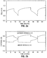
- Figure 2a shows the voltage versus time plot for the battery of Example 1.
- Figure 2b shows the voltage versus time plot for each electrode of the battery of Example 1 versus the standard hydrogen electrode.
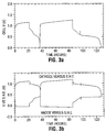
- Figure 3a shows the voltage versus time plot for the battery of Example 2.
- Figure 3b shows the voltage versus time plot for each electrode of the battery of Example 2 versus the standard hydrogen electrode.
- Figure 4 depicts the absolute voltage of several half cell reactions relevant to Example 2 versus the standard hydrogen electrode.
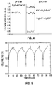
- Figure 5 depicts the voltage versus time plot for the first five cycles of battery no. 9 in Example 3.
- a cathode 1 comprises a first insertion compound in electrical contact with a cathode current collector 2.
- insertion compounds are broadly defined as host materials into which a species can be inserted and extracted without adverse irreversible effect on the crystal structure of the host).
- An anode 3 comprises a second insertion compound in electrical contact with an anode current collector 4.
- cathode 1 and anode 3 is an aqueous electrolyte 5 comprising a dissolved salt of the inserted species A of the battery.
- the inserted species A can be an alkali or alkaline earth metal.
- ions of A migrate to and from each electrode 1,3 through aqueous electrolyte 5. Concurrently, electrons migrate to and from each electrode 1,3 via external circuit 6.
- the battery contents are housed in a container 7.
- a variety of actual constructions, sizes, configurations, etc. may be employed that show similarities to both commercial aqueous and non-aqueous batteries. Preferred embodiments will combine the advantages of both where possible depending on the application.
- Oxygen can be generated at the cathode 1 via the reaction 20H (aq) - ⁇ H 2 O + 1 ⁇ 2 O 2(g) + 2e - at + 0.401V versus the standard hydrogen electrode (S.H.E.) for species in the standard state.
- hydrogen can be generated in principle at the anode 3 via the reaction H 2 O + e - ⁇ OH - + 1 ⁇ 2 H 2 at -0.83V versus S.H.E for species in the standard state.
- practical batteries may be constructed that operate beyond these limits (ie. Pb acid batteries with 2V operating potential).
- the presence of the dissolved salts in the electrolyte can modify the potential at which this decomposition occurs.
- the difference between the potentials of the first and second insertion compounds is ideally as great as possible without causing electrolysis of the electrolyte or other unwanted reactions.
- the voltage profile of preferred insertion compounds as a function of the amount of species A inserted is relatively flat or constant. In this way, large amounts of species A might be inserted or removed without reducing the operating voltage of the battery and also without exceeding decomposition limits for the electrolyte.
- a suitably chosen electrolyte may itself have a wide voltage stability range and may also widen the voltage range for kinetic stability of the possible electrode materials.
- Co-pending Canadian Patent Application Serial No. (unassigned), filed on 28 January, 1994, "AQUEOUS ELECTROCHEMICAL PREPARATION OF INSERTION COMPOUNDS AND USE IN NON-AQUEOUS RECHARGEABLE BATTERIES”, invented by Wu LI and Jeffrey Raymond Dahn discloses basic aqueous solutions and principles for selection that provide stability for certain insertion compounds that are not stable in pure water (or in acidic environments).
- embodiments of the invention may include those having neutral or somewhat acidic electrolytes, it may be advantageous to employ a basic electrolyte wherein the pH is greater than 7.
- the diffusion coefficients of the inserted species A in preferred insertion compounds are small enough such that these compounds must be used in powdered form in practical applications. This is generally desired anyway in the synthesis of many of these materials. Since aqueous electrolytes have higher ionic conductivities than non-aqueous electrolytes, it will be expected that insertion compound powders may be employed, where desired, wherein the particle size of the powders is somewhat larger than the particle size currently used in conventional lithium ion batteries. Also, preferred insertion compounds may not have satisfactory electronic conductivity. Hence, actual electrodes might be expected to be fabricated using suitable conductive dilutants and binders (as in lithium ion batteries) or using sintered plates (as in NiCd batteries). It is expected that the electrode thicknesses may be similar to those for standard aqueous batteries for a given rate requirement.
- separator material (not shown in Figure 1) is employed to allow the maximum loading of active contents in the battery.
- Thin microporous separators may be employed but are not required. If conventional aqueous battery electrode thicknesses are employed, then it may be advantageous to use conventional aqueous battery separators.
- electrolyte selection for a battery according to the invention are similar to those for conventional aqueous electrochemical systems.
- Preferred insertion compounds for use as electrodes may however require a certain minimum basic pH for stability.
- electrolytes preferably have high ionic conductivity and have sufficient salt concentrations to prevent electrolyte depletion during operation of the battery. In certain circumstances, it may be desirable to use more than one dissolved salt in the electrolyte in order to meet conditions that may be mutually exclusive when using a single salt.
- Example 2 An illustration of this possibility is described in Example 2 (below) wherein a relatively small concentration of LiOH is employed (the intention being to maintain stability of both a lithiated and a delithiated manganese oxide electrode) in combination with a relatively large concentration of LiCl (the intention being to provide better ionic conductivity).
- the system described above is an example of a salt combination wherein the cations of the two salts are the same but the anions are different. It may be of advantage for other reasons to employ a salt combination wherein two or more salts have common anions but different cations. However, such a combination would have to be compatible with the insertion characteristics of the electrode materials.
- Solvent mixtures may also be preferred over water alone for certain reasons. As with water, many alcohols and other solvents are not suitable for use in conventional non-aqueous lithium batteries since these solvents can react with the electrode material. However, such solvents might be suitable in certain embodiments of the invention. In commercial Li ion batteries, it is conventional to load the total amount of the inserted species A into the first insertion compound prior to constructing the battery. For batteries of the invention however, it may be advantageous to load a portion of the total amount of the inserted species A into either first or second insertion compounds or both. In other circumstances, it may be desirable to add an excess of a salt of A in order to electrochemically insert additional species A into an electrode and hence into the battery prior to completing the battery assembly.
- Hardware requirements for the batteries of the invention can also be expected to share similarities to other aqueous systems.
- This hardware includes the current collectors and container. Consideration with regards to possible chemical and/or electrochemical corrosion must be made in the choice of this hardware, particularly if strongly basic electrolytes are employed.
- batteries can otherwise be expected to have characteristics adopted from both aqueous and non-aqueous commercial batteries.
- constructions having spirally wound electrodes, stacked electrode plates, bobbin formats, or the like, can be envisaged.
- Pb acid batteries it may be desirable to adopt a design that allows for replenishment of the electrolyte over time.
- Li 0.36 MnO 2 with the ⁇ -MnO 2 structure was prepared by reacting LiOH.H 2 O with electrolytic manganese dioxide (TAD #1 grade of Mitsui). The materials were thoroughly mixed as described in U.S. Patent 4,959,282 and were then heated at 350°C for several hours in air.
- the spinel LiMn 2 O 4 was synthesized from Li 2 CO 3 and Chemical Manganese Dioxide (CMD). Stoichiometric ratios of the reactants were mixed and heated at 750°C in air for 24 hours. The lattice constant of this material was 8.246 ⁇ , in good agreement with the literature value (M.M. Thackeray et al, J. Electrochem. Soc. 137 , 769 (1990)).
- Electrodes were prepared by sandwiching an amount of each aforementioned material between two titanium bars thus creating Ti-Li 0.36 MnO 2 -Ti and Ti-LiMn 2 O 4 -Ti anode and cathode sandwiches respectively.
- the titanium bars were 3mm thick, 25mm wide, and about 150mm long and served as both mount and current collector. Only about 50mm of one end of each bar was actually coated with active insertion compound powder. Each bar was drilled in this region with about twenty uniformly spaced 2mm diameter holes.
- Electrode pastes of each Li-Mn-O material comprising Li-Mn-O powder, Super S (trademark of Ensagri) carbon black, and polyvinylidene fluoride in a weight ratio of 87:10:3 were made by mixing the components in N-methylpyrollidinone (NMP) solvent. Each paste was spread onto two titanium bars and was pushed into the holes to ensure good bonding. The bars were then clamped together so that the paste coatings touched, to make a Ti-(Li-Mn-O)-Ti sandwich. The paste was dried by placing the assembly in a drying oven at 105°C in air to evaporate the NMP. Electrodes contained about 2.0 grams of Li-Mn-O powder over an area of 5cm x 2.5cm. The thickness of the Li-Mn-O layer between the two Ti bars was about 2mm.
- An aqueous electrochemical cell was made in a Pyrex (trade-mark) beaker with electrodes inserted from the top as illustrated schematically in Figure 1.
- the paste coated ends of the two electrodes were immersed to a depth of about 70mm in the electrolyte in the beaker and the beaker was covered with a Lucite (trade-mark) lid.
- the electrode spacing was 25mm.
- a Ag/AgCl reference electrode was inserted midway between the two working electrodes.
- the electrolyte was 1M LiOH in water and the cell was operated at 20°C.
- the working electrodes were connected to a current supply. The voltage between the two working electrodes was monitored as was the voltage between the reference electrode and the LiMn 2 O 4 cathode.
- Figure 2a shows the voltage versus time for the cell of this example as it is first charged to about 0.7 volts, discharged to 0.0 volts, charged to 0.8 volts and then discharged to 0.0 volts again.
- Figure 2b shows the voltages of each working electrode versus S.H.E. (calculation based on the Ag/AgCl reference data). The anode is seen to reach potentials where oxygen generation might be expected. This could account for the fact that the charge capacity is greater than the corresponding capacity observed during discharge. A change to the electrolyte might eliminate this problem and is illustrated in Example 2.
- Example 1 Two 2 gram sandwich electrodes, both made of LiMn 2 O 4 , were prepared as in Example 1. These were assembled into a cell with a reference electrode as before, except that here the electrolyte was 5M LiCl in H 2 O, whose pH was adjusted with LiOH to be pH 11. The cell was operated with charge and discharge currents of 2mA at a temperature of 20°C.
- Figure 3a shows the voltage between the working electrode terminals as the cell of this example is first charged to 1.15 volts, discharged to 0.0 V, charged to 1.25 volts and discharged again to 0.0V. For these cycles, the coulometric efficiency and the cell terminal voltage is much improved over the cell of Example 1.
- the second discharge cycle lasts about 40 hours and therefore corresponds to a change of ⁇ n 0.3 in each Li 1 ⁇ n Mn 2 O 4 electrode. This is roughly 45 mAh/g of specific capacity (based on a sum of both electrode weights). It should be noted that this particular cell was not tested further to determine its ultimate capacity because the cell hardware was required for other testing.
- Figure 3b shows the voltage of each electrode versus S.H.E.
- Li 1-n Mn 2 O 4 with n approximately equal to one will spontaneously react with concentrated LiOH solutions, producing LiMn 2 O 4 , oxygen, and water. Therefore, it is unlikely that a Li 1-n Mn 2 O 4 electrode can be optimally charged (ie. removing maximum Li) in a concentrated LiOH solution.
- the reactions and potentials for oxygen evolution at the Li 1-n Mn 2 O 4 cathode
- hydrogen evolution at the Li 1+n Mn 2 O 4 anode
- the reaction 2C1 - Cl 2 +2e - which could occur at the cathode does not, because the standard potential for this reaction is well above that of Li 1-n Mn 2 O 4 .
- Other lithium salts may be similarly suitable.
- a matrix of laboratory size batteries was prepared employing several different anodes and electrolytes in two different types of container.
- a slurry of active electrode powder, Super S (trademark of Ensagri) carbon black, and ethylene propylene diene monomer (EPDM) binder was prepared in a weight ratio of 87:10:3 in cyclohexane solvent.
- the mass of active electrode powder in each slurry was about 5 grams.
- Each slurry was thoroughly blended for about 10 minutes and was then spread in a puddle on a glass plate. The puddle was continually agitated and stirred with a spoon while the cyclohexane evaporated. This stirring was intended to ensure uniform distribution of the binder.
- Each tabletting powder was used to prepare electrode tablets. 0.1 grams of tabletting powder was loaded into a 0.8 mm diameter tablet press and pressed using a 4000 Newton force. Robust tablets about 1 mm thick and with about 50% porosity were formed. Tablets of this type were used in all tests of the Example 3 matrix. Anode and cathode tablets each contained about 87 mg of active electrode powder.
- the first type of container used in the matrix comprised two titanium contact plates which could be screwed together with 1/4" #20 nylon screws.
- an anode tablet, a Celgard® 3500 separator (a wettable microporous polypropylene film), and a cathode tablet were stacked and then squeezed together by the two titanium contact plates.
- the tablets and separator were next thoroughly wetted with the appropriate aqueous electrolyte.
- this assembly was placed in a polyethylene bag to seal the contents during testing.
- this type of construction will be referred to as Ti type.
- the second type of container used was 1225 size commercial coin cell hardware (12 mm in diameter and 2.5 mm thick).
- the coin cell cap (at anode potential) was made of 304 stainless steel.
- the coin cell case (at cathode potential) was made of Shomac 30-2 (trademark).
- the sealing gasket was made of polypropylene.
- Battery construction consisted of wetting the appropriate tablets and a Celgard® 3500 separator with aqueous electrolyte, stacking them appropriately into the coin cell, and crimping the coin cell container shut afterwards.
- this type of construction will be referred to as 1225 type.
- the active powder used for the cathode tablets was LiMn 2 O 4 prepared as described in Example 1.
- three different active powders were used for the anode tablets. These were LiMn 2 O 4 , Li 0.36 MnO2 with the ⁇ -MnO 2 structure, and VO 2 (B).
- the first two of these powders were prepared as in Example 1.
- the VO 2 (B) was made according to the methods outlined in U.S. Patent No. 4,965,150.
- 50.0 grams of ammonium vanadate was reduced under flowing ammonia at 350 °C for 18 hours followed by drying under argon at 350 °C for a further 12 hours. The mass loss observed suggested that the final product stoichiometry was VO 1.97 (B).
- aqueous electrolytes were employed wherein the salts were selected from the group consisting of LiOH, LiCl, LiNO 3 , Li 2 SO 4 , or Li(acetate).
- Table 1 A tabulated summary of the battery construction, upper voltage limits used, and capacities observed on cycling are shown in Table 1. In many instances, a significant capacity is observed on the first charge and is roughly maintained after 2 complete charge-discharge cycles. However, in one instance (battery no. 6), lower capacity results were seen with 1225 type construction than with Ti type construction. Also, in some instances (battery nos. 6 or 10), a significant capacity loss occurred between the first and second discharges. The reasons for this are not yet completely understood.
- Battery nos. 8 and 9 with VO 2 (B) anodes were expected to give operating voltages near 1.5 V since the capacity of VO 2 (B) anode is attained mainly at 2.5 V versus Li and the capacity of the LiMn 2 O 4 cathode is attained mainly at 4.0 V versus Li.
- Figure 5 shows the voltage versus time data for the first five cycles of battery no. 9. The cycling is highly reversible and the average voltage was indeed near 1.5 V. (Note that there was some erratic behaviour seen in the battery voltage during the first charge that did not appear subsequently. The cause for this has not yet been confirmed.)
- the battery capacity is about 10 mAh and the tablet weights together total about 200 mg (not including the electrolyte). This gives a gravimetric energy density of 75 Whr/kg based on the two electrodes alone.
Landscapes
- Chemical & Material Sciences (AREA)
- Chemical Kinetics & Catalysis (AREA)
- Electrochemistry (AREA)
- General Chemical & Material Sciences (AREA)
- Engineering & Computer Science (AREA)
- Manufacturing & Machinery (AREA)
- Inorganic Chemistry (AREA)
- Secondary Cells (AREA)
- Battery Electrode And Active Subsutance (AREA)
Claims (22)
- Eine wiederaufladbare Batterie, die konstruiert ist aus:(a) einer Kathode aus einer ersten Einlagerungsverbindung mit eingelagerter Spezies A, wobei die Menge an eingelagerter Spezies A bei Entladung ansteigt und bei Wiederaufladung der Batterie abnimmt, wobei A zur Gruppe der Alkalimetalle und Erdalkalimetalle gehört;(b) einer Anode aus einer zweiten Einlagerungsverbindung mit eingelagerter Spezies A, wobei die Menge an eingelagertem A bei Entladung abnimmt und bei Wiederaufladung der Batterie ansteigt; und(c) einem Elektrolyten aus einem Salz von Spezies A, gelöst in einer Lösungsmittelmischung, dadurch gekennzeichnet, daß die Lösungsmittelmischung wäßrig ist und das Salz von Spezies A in einer Konzentration in dem Lösungsmittel gelöst ist, daß sowohl die erste als auch die zweite Einlagerungsverbindung über spezifizierte entsprechende Bereiche von eingelagertem A kinetisch stabil darin sind.
- Eine wiederaufladbare Batterie nach Anspruch 1, wobei der pH des Elektrolyten größer als 7 ist.
- Eine wiederaufladbare Batterie nach Anspruch 1, wobei A Lithium ist.
- Eine wiederaufladbare Batterie nach Anspruch 3, wobei die erste Einlagerungsverbindung ein Lithiumübergangsmetalloxid ist.
- Eine wiederaufladbare Batterie nach Anspruch 4, wobei die erste Einlagerungsverbindung ein Lithiummanganoxid ist.
- Eine wiederaufladbare Batterie nach Anspruch 5, wobei das Lithiummanganoxid Spinell LixMn2O4 ist, wobei x eine Zahl im Bereich von 0 bis 2 ist.
- Eine wiederaufladbare Batterie nach Anspruch 3, wobei die zweite Einlagerungsverbindung ein Lithiumübergangsmetalloxid ist.
- Eine wiederaufladbare Batterie nach Anspruch 7, wobei die zweite Einlagerungsverbindung ein Lithiummanganoxid ist.
- Eine wiederaufladbare Batterie nach Anspruch 8, wobei das Lithiummanganoxid Spinell LixMn2O4 ist, wobei x eine Zahl im Bereich von 0 bis 2 ist.
- Eine wiederaufladbare Batterie nach Anspruch 8, wobei das Lithiummanganoxid LiyMnO2 mit einer γ-MnO2-Struktur ist, wobei y eine Zahl im Bereich von 0 bis 1 ist.
- Eine wiederaufladbare Batterie nach Anspruch 7, wobei die zweite Einlagerungsverbindung ein Lithiumvanadiumoxid ist.
- Eine wiederaufladbare Batterie nach Anspruch 11, wobei das Lithiumvanadiumoxid LizVO2(B) ist, wobei z eine Zahl im Bereich von 0 bis 0,5 ist.
- Eine wiederaufladbare Batterie nach Anspruch 1, wobei A Lithium ist und das Salz von A LiOH, LiCl, LiNO3, Li2SO4 oder Li(acetat) ist.
- Eine wiederaufladbare Batterie nach Anspruch 2, wobei der Elektrolyt außerdem ein zusätzliches Hydroxidsalz umfaßt, wobei die Konzentration von besagtem zusätzlichen Hydroxidsalz geringer ist als die Konzentration des Salzes von A.
- Eine wiederaufladbare Batterie nach Anspruch 14, wobei A Lithium ist, das Salz von A LiCl, LiNO3, Li2SO4 oder Li(acetat) ist und das zusätzliche Hydroxidsalz LiOH ist.
- Ein Verfahren zur Herstellung einer wiederaufladbaren Batterie, welches einschließt:(a) Auswählen einer ersten Einlagerungsverbindung, die zur Einlagerung von Spezies A in der Lage ist, wobei A zur Gruppe der Alkalimetalle oder Erdalkalimetalle gehört;(b) Auswählen einer zweiten Einlagerungsverbindung, die zur Einlagerung von Spezies A in der Lage ist;(c) Auswählen eines Elektrolyten, der ein Salz von Spezies A einschließt, das in einer Lösungsmittelmischung gelöst ist;(d) Konstruieren einer Batterie, die eine Kathode aus der ersten Einlagerungsverbindung; eine Anode aus der zweiten Einlagerungsverbindung; eine Gesamtmenge an eingelagerter Spezies A; Trennmittel zur elektrischen Trennung der Kathode von der Anode; Kathodenstromabnehmermittel in elektrischem Kontakt mit der Kathode; Anodenstromabnehmermittel in elektrischem Kontakt mit der Anode; und einen Behälter, der die Kathode, die Anode, die Trennmittel, die Kathodenstromabnehmermittel und die Anodenstromabnehmermittel aufnimmt, einschließt; dadurch gekennzeichnet, daß die Lösungsmittelmischung wäßrig ist und die Konzentration des Salzes von Spezies A in der wäßrigen Lösungsmittelmischung so ausgewählt ist, daß sowohl die erste als auch die zweite Einlagerungsverbindung über bestimmte entsprechende Bereiche von eingelagertem A kinetisch stabil darin sind.
- Ein Verfahren nach Anspruch 16, wobei ein Teil der eingelagerten Spezies A im Bereich von Null bis zur Gesamtmenge vor dem Zusammenbau in die erste Einlagerungsverbindung der Batterie eingelagert wird.
- Ein Verfahren nach Anspruch 16, wobei ein Teil der eingelagerten Spezies A im Bereich von Null bis zur Gesamtmenge vor dem Zusammenbau in die zweite Einlagerungsver bindung der Batterie eingelagert wird.
- Ein Verfahren nach Anspruch 16, wobei ein Teil der eingelagerten Spezies A im Bereich von Null bis zur Gesamtmenge mit elektrochemischen Mitteln in entweder die erste oder die zweite Einlagerungsverbindung eingelagert wird, wobei der Anteil aus dem Salz von Spezies A stammt.
- Ein Verfahren nach Anspruch 16, wobei ein Elektrolyt ausgewählt wird, der außerdem ein zusätzliches Hydroxidsalz umfaßt, wobei die Konzentration besagten zusätzlichen Hydroxidsalzes geringer ist als die Konzentration des Salzes von Spezies A.
- Ein Verfahren nach Anspruch 16, wobei die ausgewählte erste und die ausgewählte zweite Einlagerungsverbindung identisch sind.
- Ein Verfahren zur Herstellung einer wiederaufladbaren Batterie, die konstruiert ist aus einer Kathode aus einer ersten Einlagerungsverbindung, die zur Einlagerung von Spezies A in der Lage ist, wobei A zur Gruppe der Alkalimetalle oder Erdalkalimetalle gehört; einer Anode aus einer zweiten Einlagerungsverbindung, die zur Einlagerung von Spezies A in der Lage ist; einem Elektrolyten; einer Gesamtmenge von eingelagerter Spezies A; Trennmitteln zum elektrischen Trennen der Kathode von der Anode; Kathodenstromabnehmermitteln in elektrischem Kontakt mit der Kathode; Anodenstromabnehmermitteln in elektrischem Kontakt mit der Anode; und einem Behälter, der die Kathode, die Anode, die eingelagerte Spezies A, die Trennmittel, den Kathodenstromabnehmer und den Anodenstromabnehmer aufnimmt; dadurch gekennzeichnet, daß der Elektrolyt aus einem Salz von A besteht, das in einer wäßrigen Lösungsmittelmischung gelöst ist, und die Konzentration des Salzes von Spezies A in der Lösungsmittelmischung so ausgewählt ist, daß sowohl die erste als auch die zweite Einlagerungsverbindung über bestimmte entsprechende Bereiche von eingelagertem A kinetisch stabil darin sind.
Applications Claiming Priority (3)
| Application Number | Priority Date | Filing Date | Title |
|---|---|---|---|
| CA2114902 | 1994-02-03 | ||
| CA002114902A CA2114902C (en) | 1994-02-03 | 1994-02-03 | Aqueous rechargeable battery |
| PCT/CA1995/000042 WO1995021470A1 (en) | 1994-02-03 | 1995-01-27 | Aqueous rechargeable battery |
Publications (2)
| Publication Number | Publication Date |
|---|---|
| EP0742961A1 EP0742961A1 (de) | 1996-11-20 |
| EP0742961B1 true EP0742961B1 (de) | 1997-11-12 |
Family
ID=4152852
Family Applications (1)
| Application Number | Title | Priority Date | Filing Date |
|---|---|---|---|
| EP95906859A Expired - Lifetime EP0742961B1 (de) | 1994-02-03 | 1995-01-27 | Wässrige wiederaufladbare batterie |
Country Status (7)
| Country | Link |
|---|---|
| US (1) | US6403253B1 (de) |
| EP (1) | EP0742961B1 (de) |
| JP (1) | JP4301527B2 (de) |
| AU (1) | AU1529595A (de) |
| CA (1) | CA2114902C (de) |
| DE (1) | DE69501039T2 (de) |
| WO (1) | WO1995021470A1 (de) |
Families Citing this family (52)
| Publication number | Priority date | Publication date | Assignee | Title |
|---|---|---|---|---|
| CA2186099A1 (en) * | 1996-09-20 | 1996-11-18 | David Stanley Wainwright | Aqueous rechargeable battery |
| KR100777506B1 (ko) * | 1998-10-20 | 2007-11-16 | 프라운호퍼-게젤샤프트 츄어 푀르더룽 데어 안게반텐 포르슝에.파우. | 무기질 액체 전도체를 함유한 페이스트형 물질과, 이 물질로 제조된 층 및 전기화학적 소자 |
| JP2001052747A (ja) * | 1999-08-06 | 2001-02-23 | Matsushita Electric Ind Co Ltd | リチウム二次電池 |
| JP4686871B2 (ja) * | 2001-02-28 | 2011-05-25 | 株式会社豊田中央研究所 | リチウム二次電池 |
| JP4716072B2 (ja) * | 2001-07-02 | 2011-07-06 | 株式会社豊田中央研究所 | 水系リチウム二次電池負極活物質用リチウムバナジウム複合酸化物、その製造方法およびそれを用いたリチウム二次電池 |
| US7189475B2 (en) | 2000-07-27 | 2007-03-13 | Kabushiki Kaisha Toyota Chuo Kenkyusho | Lithium secondary battery |
| JP4380265B2 (ja) * | 2003-08-25 | 2009-12-09 | 株式会社豊田中央研究所 | 水系リチウム二次電池 |
| US8137842B2 (en) * | 2004-01-22 | 2012-03-20 | The Gillette Company | Battery cathodes |
| JP2006120367A (ja) * | 2004-10-19 | 2006-05-11 | Toyota Central Res & Dev Lab Inc | 正極活物質及び水系リチウム二次電池 |
| JP4691966B2 (ja) * | 2004-11-18 | 2011-06-01 | 株式会社豊田中央研究所 | リチウム二次電池 |
| JP2006179424A (ja) * | 2004-12-24 | 2006-07-06 | Toyota Motor Corp | 電池の製造方法 |
| JP5256649B2 (ja) * | 2007-05-31 | 2013-08-07 | 株式会社豊田中央研究所 | 水系リチウム二次電池 |
| US8507130B2 (en) | 2007-07-11 | 2013-08-13 | Kabushiki Kaisha Toyota Chuo Kenkyusho | Water based lithium secondary battery |
| JP2009146756A (ja) * | 2007-12-14 | 2009-07-02 | Toyota Central R&D Labs Inc | 水系リチウムイオン二次電池 |
| US10320033B2 (en) | 2008-01-30 | 2019-06-11 | Enlighten Innovations Inc. | Alkali metal ion battery using alkali metal conductive ceramic separator |
| JP5194979B2 (ja) * | 2008-04-14 | 2013-05-08 | 株式会社豊田中央研究所 | 水系リチウムイオン二次電池 |
| US20100221596A1 (en) * | 2009-02-06 | 2010-09-02 | Huggins Robert A | Systems, methods of manufacture and use involving lithium and/or hydrogen for energy-storage applications |
| JP5299105B2 (ja) * | 2009-06-16 | 2013-09-25 | ソニー株式会社 | 二酸化バナジウムナノワイヤとその製造方法、及び二酸化バナジウムナノワイヤを用いたナノワイヤデバイス |
| US8318354B2 (en) * | 2010-04-27 | 2012-11-27 | Toyota Motor Engineering & Manufacturing North America | Electrochemical device with a magnesium anode and a stable, safe electrolyte compatible with sulfur |
| CN103119775B (zh) | 2010-09-30 | 2015-06-10 | 川崎重工业株式会社 | 以质子为嵌入物的二次电池用负极及具备该负极的二次电池 |
| US8945751B2 (en) * | 2011-07-19 | 2015-02-03 | Aquion Energy, Inc. | High voltage battery composed of anode limited electrochemical cells |
| US9570741B2 (en) * | 2012-03-21 | 2017-02-14 | Duracell U.S. Operations, Inc. | Metal-doped nickel oxide active materials |
| US9028564B2 (en) | 2012-03-21 | 2015-05-12 | The Gillette Company | Methods of making metal-doped nickel oxide active materials |
| US8945756B2 (en) | 2012-12-12 | 2015-02-03 | Aquion Energy Inc. | Composite anode structure for aqueous electrolyte energy storage and device containing same |
| US9431682B2 (en) * | 2012-12-19 | 2016-08-30 | Ceramatec, Inc. | Degradation protection of solid alkali ion conductive electrolyte membrane |
| BR112015021457B1 (pt) | 2013-03-07 | 2021-11-23 | Daramic, Llc | Métodos de prevenção ou redução de oxidação de separador em uma bateria de chumbo ácido inundada surgindo do uso de água ou ácido contendo contaminantes |
| JP6612238B2 (ja) * | 2014-01-28 | 2019-11-27 | チュンシェン ワン | 多電子水系電池 |
| US10763491B2 (en) | 2014-04-01 | 2020-09-01 | The Research Foundation For The State University Of New York | Low-temperature synthesis process of making MgzMxOy, where M is Mn, V or Fe, for manufacture of electrode materials for group II cation-based batteries |
| JP2017027944A (ja) * | 2015-07-24 | 2017-02-02 | 御国色素株式会社 | リチウムイオン電池 |
| CN107925131B (zh) | 2016-02-01 | 2021-08-13 | 株式会社东芝 | 二次电池、组电池、电池包及车辆 |
| KR101889219B1 (ko) | 2016-03-16 | 2018-08-16 | 가부시끼가이샤 도시바 | 이차 전지, 전지 팩 및 차량 |
| JP6704822B2 (ja) | 2016-09-16 | 2020-06-03 | 株式会社東芝 | 二次電池、電池パック及び車両 |
| JP6736436B2 (ja) | 2016-09-16 | 2020-08-05 | 株式会社東芝 | 二次電池、電池パック及び車両 |
| JP6692308B2 (ja) | 2017-02-21 | 2020-05-13 | 株式会社東芝 | 二次電池、組電池、電池パック及び車両 |
| JP6672208B2 (ja) | 2017-03-17 | 2020-03-25 | 株式会社東芝 | 二次電池、電池パック及び車両 |
| US11431035B2 (en) | 2017-03-17 | 2022-08-30 | Kabushiki Kaisha Toshiba | Secondary battery, battery pack and vehicle |
| US20180269538A1 (en) * | 2017-03-17 | 2018-09-20 | Kabushiki Kaisha Toshiba | Secondary battery, battery pack and vehicle |
| US10862092B2 (en) | 2017-03-21 | 2020-12-08 | Kabushiki Kaisha Toshiba | Secondary battery with separator having a solid electrolyte, battery pack, and vehicle |
| JP6659608B2 (ja) | 2017-03-21 | 2020-03-04 | 株式会社東芝 | 二次電池、電池パック及び車両 |
| JP6383038B1 (ja) | 2017-03-22 | 2018-08-29 | 株式会社東芝 | 二次電池、電池パック及び車両 |
| JP6819518B2 (ja) * | 2017-09-06 | 2021-01-27 | トヨタ自動車株式会社 | 水系リチウムイオン二次電池 |
| JP6746549B2 (ja) | 2017-09-19 | 2020-08-26 | 株式会社東芝 | 二次電池、電池パック及び車両 |
| CN108172911A (zh) * | 2018-01-11 | 2018-06-15 | 武汉大学 | 一种全钒水溶液锂离子电池 |
| US11251430B2 (en) | 2018-03-05 | 2022-02-15 | The Research Foundation For The State University Of New York | ϵ-VOPO4 cathode for lithium ion batteries |
| JP6889125B2 (ja) | 2018-03-16 | 2021-06-18 | 株式会社東芝 | セパレータ、電極群、二次電池、電池パック、車両、及び定置用電源 |
| JP7067985B2 (ja) | 2018-03-22 | 2022-05-16 | 株式会社東芝 | 二次電池、電池パック、車両、及び定置用電源 |
| US10873080B2 (en) | 2018-03-22 | 2020-12-22 | Kabushiki Kaisha Toshiba | Secondary battery, battery pack, vehicle, and stationary power supply |
| WO2020054099A1 (en) | 2018-09-13 | 2020-03-19 | Kabushiki Kaisha Toshiba | Secondary battery, battery pack, vehicle, and stationary power supply |
| JP6951307B2 (ja) | 2018-09-13 | 2021-10-20 | 株式会社東芝 | 二次電池、電池パック、車両及び定置用電源 |
| JP7010866B2 (ja) | 2019-03-14 | 2022-01-26 | 株式会社東芝 | 二次電池、電池パック、車両、及び定置用電源 |
| JP7118936B2 (ja) | 2019-09-13 | 2022-08-16 | 株式会社東芝 | セパレータ、電極群、二次電池、電池パック、車両及び定置用電源 |
| JP7191873B2 (ja) | 2020-01-17 | 2022-12-19 | 株式会社東芝 | 充放電制御装置、充放電システム、充放電制御方法及び充放電制御プログラム |
Family Cites Families (9)
| Publication number | Priority date | Publication date | Assignee | Title |
|---|---|---|---|---|
| US4312930A (en) | 1978-09-29 | 1982-01-26 | Union Carbide Corporation | MnO2 Derived from LiMn2 O4 |
| DE3068002D1 (en) | 1979-04-05 | 1984-07-05 | Atomic Energy Authority Uk | Electrochemical cell and method of making ion conductors for said cell |
| US4702977A (en) | 1985-04-30 | 1987-10-27 | Toshiba Battery Co., Ltd. | Secondary battery using non-aqueous solvent |
| JPS6223433A (ja) | 1985-07-24 | 1987-01-31 | Kashima Eng Kk | 触媒抜出用アンロ−ダ |
| US5028500A (en) | 1989-05-11 | 1991-07-02 | Moli Energy Limited | Carbonaceous electrodes for lithium cells |
| US5130211A (en) | 1990-10-24 | 1992-07-14 | Her Majesty The Queen In Right Of The Provence Of British Columbia | Electrolyte solution sequestering agents for electrochemical cells having carbonaceous electrodes |
| JP3445654B2 (ja) * | 1993-03-17 | 2003-09-08 | ウィルソン グレイトバッチ リミテッド | 電気化学電池およびそのカソード |
| US5312623A (en) * | 1993-06-18 | 1994-05-17 | The United States Of America As Represented By The Secretary Of The Army | High temperature, rechargeable, solid electrolyte electrochemical cell |
| US5376475A (en) * | 1994-03-16 | 1994-12-27 | Ovonic Battery Company, Inc. | Aqueous lithium-hydrogen ion rechargeable battery |
-
1994
- 1994-02-03 CA CA002114902A patent/CA2114902C/en not_active Expired - Lifetime
-
1995
- 1995-01-27 AU AU15295/95A patent/AU1529595A/en not_active Abandoned
- 1995-01-27 WO PCT/CA1995/000042 patent/WO1995021470A1/en not_active Ceased
- 1995-01-27 EP EP95906859A patent/EP0742961B1/de not_active Expired - Lifetime
- 1995-01-27 DE DE69501039T patent/DE69501039T2/de not_active Expired - Lifetime
- 1995-01-27 JP JP52028695A patent/JP4301527B2/ja not_active Expired - Fee Related
- 1995-03-22 US US08/408,315 patent/US6403253B1/en not_active Expired - Lifetime
Also Published As
| Publication number | Publication date |
|---|---|
| CA2114902A1 (en) | 1995-08-04 |
| US6403253B1 (en) | 2002-06-11 |
| WO1995021470A1 (en) | 1995-08-10 |
| JPH09508490A (ja) | 1997-08-26 |
| EP0742961A1 (de) | 1996-11-20 |
| CA2114902C (en) | 2001-01-16 |
| DE69501039D1 (de) | 1997-12-18 |
| DE69501039T2 (de) | 1998-03-05 |
| AU1529595A (en) | 1995-08-21 |
| JP4301527B2 (ja) | 2009-07-22 |
Similar Documents
| Publication | Publication Date | Title |
|---|---|---|
| EP0742961B1 (de) | Wässrige wiederaufladbare batterie | |
| Besenhard | Handbook of battery materials | |
| EP3379625B1 (de) | Sekundärbatterie, batteriepack und fahrzeug | |
| EP0656667B1 (de) | Inversspinell Verbindungen als Kathoden für Lithiumbatterien | |
| US10333138B2 (en) | Cathode additive for rechargeable sodium batteries | |
| EP0752162B1 (de) | Hochfrequenz energiezelle | |
| US8313859B2 (en) | Battery cathodes | |
| US20040086784A1 (en) | Lithium-containing phosphates, methods of preparation, and uses thereof | |
| US5851696A (en) | Rechargeable lithium battery | |
| CN101872860A (zh) | 正极活性物质、其制造方法及非水电解质电池 | |
| WO1996015562A9 (en) | High pulse power cell | |
| US5744265A (en) | Lithium cell having mixed lithium--metal--chalcogenide cathode | |
| US5670277A (en) | Lithium copper oxide cathode for lithium cells and batteries | |
| EP0669667B1 (de) | Wässrige elektrochemische Herstellung von Interkalierverbindungen und ihre Verwendung in nichtwässrigen wiederaufladbare Batterien | |
| JPH11120993A (ja) | 非水電解質二次電池 | |
| JPH08287914A (ja) | リチウム電池 | |
| JPH10270090A (ja) | リチウム二次電池の製造方法 | |
| US8137842B2 (en) | Battery cathodes | |
| JP2007115507A (ja) | 負極活物質及び水系リチウム二次電池 | |
| EP4160734A1 (de) | Lithiumsekundärzelle und wasserfreier elektrolyt dafür | |
| CN108028381B (zh) | 用于电池组单元的正电极的活性材料、正电极和电池组单元 | |
| JP2005071936A (ja) | 水系リチウム二次電池 | |
| Scrosati | Low Voltage Lithium-Ion Cells | |
| JP2002237300A (ja) | 二重集電体スクリーンカソードを構成するペレットを含む電池 |
Legal Events
| Date | Code | Title | Description |
|---|---|---|---|
| PUAI | Public reference made under article 153(3) epc to a published international application that has entered the european phase |
Free format text: ORIGINAL CODE: 0009012 |
|
| 17P | Request for examination filed |
Effective date: 19960430 |
|
| AK | Designated contracting states |
Kind code of ref document: A1 Designated state(s): DE FR GB |
|
| GRAG | Despatch of communication of intention to grant |
Free format text: ORIGINAL CODE: EPIDOS AGRA |
|
| 17Q | First examination report despatched |
Effective date: 19970203 |
|
| GRAH | Despatch of communication of intention to grant a patent |
Free format text: ORIGINAL CODE: EPIDOS IGRA |
|
| GRAH | Despatch of communication of intention to grant a patent |
Free format text: ORIGINAL CODE: EPIDOS IGRA |
|
| GRAA | (expected) grant |
Free format text: ORIGINAL CODE: 0009210 |
|
| AK | Designated contracting states |
Kind code of ref document: B1 Designated state(s): DE FR GB |
|
| REF | Corresponds to: |
Ref document number: 69501039 Country of ref document: DE Date of ref document: 19971218 |
|
| ET | Fr: translation filed | ||
| PLBE | No opposition filed within time limit |
Free format text: ORIGINAL CODE: 0009261 |
|
| STAA | Information on the status of an ep patent application or granted ep patent |
Free format text: STATUS: NO OPPOSITION FILED WITHIN TIME LIMIT |
|
| 26N | No opposition filed | ||
| REG | Reference to a national code |
Ref country code: GB Ref legal event code: IF02 |
|
| PGFP | Annual fee paid to national office [announced via postgrant information from national office to epo] |
Ref country code: GB Payment date: 20130125 Year of fee payment: 19 Ref country code: FR Payment date: 20130211 Year of fee payment: 19 Ref country code: DE Payment date: 20130129 Year of fee payment: 19 |
|
| REG | Reference to a national code |
Ref country code: DE Ref legal event code: R119 Ref document number: 69501039 Country of ref document: DE |
|
| GBPC | Gb: european patent ceased through non-payment of renewal fee |
Effective date: 20140127 |
|
| PG25 | Lapsed in a contracting state [announced via postgrant information from national office to epo] |
Ref country code: DE Free format text: LAPSE BECAUSE OF NON-PAYMENT OF DUE FEES Effective date: 20140801 |
|
| REG | Reference to a national code |
Ref country code: FR Ref legal event code: ST Effective date: 20140930 |
|
| REG | Reference to a national code |
Ref country code: DE Ref legal event code: R119 Ref document number: 69501039 Country of ref document: DE Effective date: 20140801 |
|
| PG25 | Lapsed in a contracting state [announced via postgrant information from national office to epo] |
Ref country code: FR Free format text: LAPSE BECAUSE OF NON-PAYMENT OF DUE FEES Effective date: 20140131 Ref country code: GB Free format text: LAPSE BECAUSE OF NON-PAYMENT OF DUE FEES Effective date: 20140127 |