EP0740619B1 - Einrichtung zum verlegen eines drahtes, seiles oder dgl. - Google Patents
Einrichtung zum verlegen eines drahtes, seiles oder dgl. Download PDFInfo
- Publication number
- EP0740619B1 EP0740619B1 EP95904964A EP95904964A EP0740619B1 EP 0740619 B1 EP0740619 B1 EP 0740619B1 EP 95904964 A EP95904964 A EP 95904964A EP 95904964 A EP95904964 A EP 95904964A EP 0740619 B1 EP0740619 B1 EP 0740619B1
- Authority
- EP
- European Patent Office
- Prior art keywords
- base frame
- equipment
- disks
- cable
- recited
- Prior art date
- Legal status (The legal status is an assumption and is not a legal conclusion. Google has not performed a legal analysis and makes no representation as to the accuracy of the status listed.)
- Expired - Lifetime
Links
Images


Classifications
-
- B—PERFORMING OPERATIONS; TRANSPORTING
- B60—VEHICLES IN GENERAL
- B60M—POWER SUPPLY LINES, AND DEVICES ALONG RAILS, FOR ELECTRICALLY- PROPELLED VEHICLES
- B60M1/00—Power supply lines for contact with collector on vehicle
- B60M1/12—Trolley lines; Accessories therefor
- B60M1/28—Manufacturing or repairing trolley lines
Definitions
- the invention relates to a device for laying a wire, rope or the like.
- a beaten medium preferably an overhead line or a catenary system, above a route with a vehicle or a vehicle set, on which at least one wire drum is mounted and at least one lifting drum , lowerable and swiveling lifting arm is provided for lifting the wire running off the wire drum to the assembly height above the travel distance, with one lifting arm being provided for each wire and a device having a mounted base frame for extending, pulling in or holding the at the free end of the lifting arm Wire is rotatably and / or pivotally arranged.
- Such a device is known from WO 92/15470.
- This device for extending, pulling in or holding the wire has a base frame which is rotatably mounted about its center point and on which at least one pair of rollers through which the wire is guided are provided on a plate.
- the pairs of rollers can each be pivoted about the shaft of a roller on the base frame by means of spring storage, the pivot points being diametrically opposite and the rollers or the roller pair being drivable.
- This device has been well preserved in that the positioning of the catenary is in the final laying position during assembly.
- the disadvantage of this device is that so-called basket formations can occur due to the pressing force of the rollers when laying media, in particular struck media, such as multi-core ropes.
- a device for temporarily installing an overhead line above a rail line with a rail vehicle is known.
- the wire drums and a lifting arm for lifting the wires to the height of the fastening hooks are provided on this rail vehicle.
- the wire drums are followed by a tension control device with which a longitudinal tensile force can be applied both to the support cable and to the contact wire.
- Disadvantages of the device are, on the one hand, that the support cable and the contact wire must always be laid in the same vertical plane and, on the other hand, that the cable under tension undergoes a change of direction after the tension control device.
- the effort for the hook search device and for the device for delivering the temporary hangers is extremely considerable.
- EP 56097 discloses a method for assembling a ferry wire, the contact wire having two components running in parallel. One component is a low-tension, current-carrying conductor line profile and the other component is a tension profile, the conductor line component being interchangeable without bracing the support component.
- DD-PS 128 887 describes a method for assembling or disassembling overhead contact lines for railways.
- the wire drum is driven and the wire is guided via a deflection mechanism.
- the disadvantage here is that the wire under tension is exposed to one or more changes in direction.
- the assembly of contact wires is known from DE-OS 20 12 248, an equipment trolley having a guide device by means of which the ropes are brought into the appropriate position.
- this device has only one lifting arm for both wires and the wires cannot be extended, caught or held at the assembly height.
- the object of the invention is to provide a device of the type cited at the beginning, with which the above disadvantages are avoided on the one hand and with the other Continuous laying of an overhead line, in particular an overhead line system, which also contains a struck medium, such as a multi-core rope, can be done in a most rational and high quality manner.
- the device according to the invention is characterized in that on the base frame or on a plate arranged on the base frame, two disks or wheels, provided with at least two grooves on the circumference, are inclined in one plane, the rope being guided in the grooves over both disks.
- the disks can be used as traction and / or braking machines via hydraulic units.
- the design of the hydraulic units for both braking and pulling results in immense assembly advantages.
- the plate or a frame is arranged on the base frame perpendicular to the base frame plane and parallel to the running direction of the rope. If the lifting arm can be swiveled beyond the track profile, the vertical disc arrangement is cheaper.
- the frame made of molded tubes for the hydraulic units serves as an oil reservoir and the hydraulic loading, preferably both hydraulic units, takes place via a control system which has correspondingly switchable hydraulic pumps and valves. This means that the rope to be laid can be moved smoothly and smoothly from standstill to maximum running speed with constant traction.
- the base frame is pivotally mounted in the center. The pivoting of the base frame ensures that the rope runs out without kinks.
- the pivotable central base frame mounting takes place in a pin mounting arranged on the lifting arm.
- a gimbal mounting of the device is provided in the simplest way.
- the journal bearing of the base frame lies below the point of force transmission of the entire device.
- the device is always self-aligned in the working direction.
- an inlet or outlet roller battery is arranged in front of or behind the disks, the outlet roller battery being longer than the inlet roller battery.
- the extension of the outlet roller battery ensures that the rope to be laid is guided properly, and the entire device is self-aligned thanks to the tensioned medium.
- Fig. 1 shows the schematic representation of the device when laying an overhead line system for rail vehicles
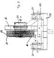
- Fig. 2 and 3 the device for extending, hauling and holding the rope.
- the vehicle 1 which can be moved on rails or the vehicle set, which of course can also be designed to be self-propelled, has two wagons intended.
- the lifting arms 4, 5 are each mounted on the loading surface of the vehicle 1 via a bogie 6, so that the lifting arms can be pivoted.
- the device 8 or 11 for extending, catching or holding the wire 9 or rope 14 is arranged via a bearing 7.
- a hydraulic cylinder 10 is provided for lifting and lowering the lifting arm 4, 5.
- the lifting arm 4, 5 can also be designed to be hydraulically retractable and extendable.
- the device 8 and 11 is, as will be described later, mounted in the lifting arm 4, 5 in such a way that the wire 9 or cable 14 running freely from the wire drum 2, 3 is positioned in the final laying position during assembly.
- the adjustment of the device 8 or 11 in the bearing 7 takes place via the hydraulic cylinder 15.
- the extension width of the lifting arms 4, 5 is dimensioned such that work can also be carried out outside the usual laying profile, ie not only above the rails, but also in the area above the railway embankment.
- the device 8 for laying the contact wire 9 - which will only be discussed briefly here - has a gimbal-mounted base frame and four pairs of rollers, two pairs of rollers being arranged opposite each other so that the wire 9 is guided between them.
- the pairs of rollers are each stored in plates and are driven together via a pinion.
- the drive pinion is connected to a hydraulic motor.
- Each pair of rollers is pivotally supported by a roller for a while, the pivoting movement being carried out via hydraulic cylinders.
- the fulcrums of these corresponding pairs of rollers are diametrically opposite, which means that the device can be used for a wide variety of wire sizes.
- the forces acting on the wire 9 can be adjusted via the hydraulic cylinders.
- the device 11 for laying a multi-core rope 14 has a short inlet roller battery 12 and a longer outlet roller battery 13.
- the device 11 is mounted such that the pin bearing 7 for the base frame 22 is below the force transmission point of the entire device 11.
- a plate 16 is provided which is perpendicular to the base frame plane and parallel to the running direction of the rope.
- This plate 16 can also be a frame.
- two disks or wheels 17 and 18 are mounted, preferably via shafts. These discs 17, 18 have a plurality of grooves 19 on the circumference for guiding the cable 14. These discs are driven by hydraulic units 20.
- the base frame 22 is provided with a bearing 21 in the center on both sides.
- the device 11 is gimbal-mounted at the free end of the lifting arm 4.
- the base frame 22 is pivotable about the bearing 21 in the direction of the rope 14 passing through.
- the bar 23 for the bearing 21 has an arm 24 parallel to the base frame plane.
- a shaft stub 27 is provided which is rotatably mounted in a tube 25 and in the arm 24.
- the tube 25 is pivotally attached to the end of the lifting arm 4.
- the tube 25 is moved via the hydraulic cylinder 15, which is attached on the one hand to the tube 25 and on the other hand to the lifting arm 4.
- the hydraulic cylinder 15 is connected to the hydraulic cylinder 10 directly via lines, so that the pipe 25 is always vertical.
- the two disks 17, 18 are inclined towards one another. As a result, the disks 17, 18 can be provided on the circumference with adjacent grooves 19.
- the cable 14 enters via the infeed roller battery 12, runs next to the first disc 18, and is immediately pulled onto the second disc and wraps around this disc at 180 °, is returned to the first disc and wraps around it at 180 °.
- the guidance of the rope is repeated according to the number of grooves.
- the two disks are inclined relative to one another by the angle. This angle is chosen such that a groove width of a dislocation is achieved when the rope runs in and a groove width of an offset is reached when the rope runs out.
- the disk diameter is chosen to be large compared to the rope diameter.
- the arrangement of two disks 17, 18 is therefore carried out so that the capstan effect occurring on one disk does not occur.
- the grooves 19 of the disks 17, 18 can be lined with plastic, in particular with neoprene.
- the grooves 19 are of course chosen so that the strongest rope with a pulling sleeve or pulling sock can still run over it.
Landscapes
- Engineering & Computer Science (AREA)
- Manufacturing & Machinery (AREA)
- Mechanical Engineering (AREA)
- Electric Cable Installation (AREA)
- Insulated Conductors (AREA)
- Installation Of Indoor Wiring (AREA)
- Ropes Or Cables (AREA)
- Storing, Repeated Paying-Out, And Re-Storing Of Elongated Articles (AREA)
- Guides For Winding Or Rewinding, Or Guides For Filamentary Materials (AREA)
- Sewing Machines And Sewing (AREA)
- Carriers, Traveling Bodies, And Overhead Traveling Cranes (AREA)
- Load-Engaging Elements For Cranes (AREA)
- Bridges Or Land Bridges (AREA)
- Light Guides In General And Applications Therefor (AREA)
- Coiling Of Filamentary Materials In General (AREA)
- Superconductors And Manufacturing Methods Therefor (AREA)
- Suspension Of Electric Lines Or Cables (AREA)
- Supports For Pipes And Cables (AREA)
- Wire Bonding (AREA)
- Electrostatic Charge, Transfer And Separation In Electrography (AREA)
Description
- Die Erfindung betrifft eine Einrichtung zum Verlegen eines Drahtes, Seiles oder dgl., insbesondere eines geschlagenen Mediums, vorzugsweise einer Oberleitung oder eines Fahrleitungssystems, oberhalb einer Fahrstrecke mit einem Fahrzeug bzw. einer Fahrzeuggarnitur, auf dem mindestens eine Drahttrommel gelagert ist und wenigstens ein heb-, senk- und schwenkbarer Hubarm zum Anheben des von der Drahttrommel ablaufenden Drahtes auf die Montagehöhe oberhalb der Fahrstrecke vorgesehen ist, wobei pro Draht ein Hubarm vorgesehen ist und am freien Ende des Hubarmes eine einen gelagerten Grundrahmen aufweisende Vorrichtung zum Ausfahren, Einholen bzw. Festhalten des Drahtes dreh- und/oder schwenkbar angeordnet ist.
- Aus der WO 92/15470 ist eine derartige Einrichtung bekannt. Diese Vorrichtung zum Ausfahren, Einholen bzw. Festhalten des Drahtes weist einen um seinen Mittelpunkt drehbar gelagerten Grundrahmen auf aufden mindestens bei auf je einer Platte angeordnete Rollenpaare durch die der Draht geführt ist, vorgesehen sind. Die Rollenpaare sind jeweils um die Welle einer Rolle auf dem Grundrahmen mittels Federspeicher schwenkbar, wobei die Drehpunkte diametral gegenüberliegen und die Rollen bzw. das Rollenpaar antreibbar sind. Diese Vorrichtung hat sich dahingehend bestens bewahrt, daß die Positionierung der Oberleitung bei der Montage in der endgültigen Verlegelage ist.
- Nachteilig ist bei dieser Vorrichtung, daß bei Verlegung von insbesondere geschlagenen Medien, wie mehradrigen Seilen, sogenannte Korbbildungen durch die Preßkraft der Rollen auftreten können.
- Darüber hinaus ist aus der DE-PS 22 11 247 eine Vorrichtung zum vorläufigen Installieren einer Oberleitung oberhalb einer Schienenstrecke mit einem Schienenfahrzeug bekannt. Auf diesem Schienenfahrzeug sind die Drahttrommeln und ein Hubarm zum Anheben der Drähte auf die Höhe der Befestigungshaken vorgesehen. Ferner ist den Drahttrommeln eine Zugspannungs-Steuervorrichtung, mit der sowohl auf das Tragseil als auch auf den Fahrdraht eine Längszugkraft aufbringbar ist, nachgeordnet. Nachteilig bei deser Vorrichtung ist einerseits, daß das Tragseil und der Fahrdraht immer in der gleichen Vertikalebene verlegt werden muß und anderseits, daß das unter Zug stehende Seil nach der Zugspannungs-Steuervorrichtung eine Richtungsänderung erfährt. Darüberhinaus ist auch der Aufwand für die Hakensuchvorrichtung und für die Vorrichtung zum Abgeben der provisorischen Hänger überaus beträchtlich.
- Ferner ist aus der EP 56097 ein Verfahren zur Montage eines Fährdrahtes, wobei der Fahrdraht zwei paralleliaufende Komponenten aufweist, bekannt. Eine Komponente ist ein zugspannungsarmes, stromführendes Schleifleitungsprofil und die andere Komponente ist ein Spannprofil, wobei die Schleifleitungskomponente ohne Abspannung der Tragkomponente auswechselbar ist.
- Aus der DE-OS 21 22 099 ist eine Vorrichtung zum Verlegen von ummantelten Fahrdraht bekannt. Diese Vorrichtung weist unter anderem einen Trommeltransportwagen mit einer Leitertrommel auf, bei der eine Backenbremse vorgesehen ist. Nachteilig dabei ist, daß aufgrund der vielen Fahrzeugeinheiten für die Verlegung ein erheblicher Personal- und Arbeitsaufwand erforderlich ist. Außerdem leidet durch die Labilität der Einheit die Kontinuität und die Qualität der verlegten Leitung.
- Gemaß der DD-PS 137 909 ist eine Seilführungsrolle zum Verlegen von Seitenfahrleitungen bekannt.
- Ferner ist noch in der DD-PS 128 887 ein Verfahren zur Montage oder Demontage von Fahrleitungen für Schienenbahnen beschrieben. Dabei wird die Drahttrommel angetrieben und der Draht über einen Umlenkmechanismus geführt. Nachteilig dabei ist, daß der unter Zugspannung stehende Draht einer oder mehrer Richtungsänderungen ausgesetzt ist.
- Weiters ist noch aus der DE-OS 20 12 248 die Montage von Fahrdrähten bekannt, wobei ein Gerätewagen eine Führungsvorrichtung besitzt, mittels derer die Seile in die entsprechende Lage gebracht werden. Jedoch weist diese Vorrichtung nur einen Hubarm für beide Drähte aufund die Drähte können auch nicht in Montagehöhe ausgefahren, eingeholt bzw. festgehalten werden.
- Aufgabe der Erfindung ist es, eine Einrichtung der eingangs zitierten Art zu schaffen, mit der einerseits die obigen Nachteile vermieden werden und mit der anderseits ein kontinuierliches Verlegen einer Oberleitung, insbesondere eines Oberleitungssystems, das auch ein geschlagenes Medium, wie ein mehradriges Seil, beinhaltet, in rationellster und in qualitätsmäßig hochstehender Weise erfolgen kann.
- Die erfindungsgemäße Einrichtung ist dadurch gekennzeichnet, daß am Grundrahmen oder auf einer am Grundrahmen angeordneten Platte zwei mit mindestens zwei Rillen am Umfang versehene, gegeneinander geneigte, Scheiben oder Räder in einer Ebene gelagert sind, wobei das Seil in den Rillen über beide Scheiben geführt ist. Mit der Erfindung ist es nicht nur möglich, den Draht oder das Seil in der nach der Montage endgültigen Lage bei der Montage zu positionieren, sondern auch erstmals gleichzeitig eine ausgezeichnete Qualität der zu verlegenden mehradrigen Seile zu erzielen. Durch den Umschließungswinkel des zu verlegenden Seiles über die beiden Scheiben in Zusammenwirken mit dem Reibungskoeffizienten können größte Zugspannungen beherrscht werden, ohne daß das Seil Quetschungen ausgesetzt ist. Unregelmäßige, radiale Krafteinwirkungen auf die Seilaußenschicht sind mit dieser Vorrichtung ausgeschlossen.
- Nach einem weiteren Merkmal der Erfindung sind die Scheiben über Hydraulikaggregate als Zug- und/oder Bremsmaschinen verwendbar. Durch die Ausführung der Hydraulikaggregate sowohl zum Bremsen als auch zum Ziehen sind immense Montagevorteile die Folge.
- Nach einem besonderen Merkmal der Erfindung ist die Platte oder ein Rahmen am Grundrahmen zur Grundrahmenebene senkrecht und parallel zur Laufrichtung des Seiles angeordnet. Bei einer Verschwenkbarkeit des Hubarmes über das Bahnprofil hinaus, ist die senkrechte Scheibenanordnung günstiger.
- Gemäß einer besonderen Ausgestaltung der Erfindung dient der aus Formrohren gebaute Rahmen für die Hydraulikaggregate als Ölbehälter und die hydraulische Beaufschlagung, vorzugsweise beider Hydraulikaggregate erfolgt über ein, entsprechend umschaltbare, hydraulische Pumpen und Ventile aufweisendes Regelsystem. Dadurch kann das zu verlegende Seil vom Stillstand bis zur maximalen Laufgeschwindigkeit bei konstanter Zugkraft stufenlos und ruckfrei bewegt werden.
- Nach einer weiteren Ausgestaltung der Erfindung ist der Grundrahmen mittig schwenkbar gelagert. Durch die Schwenkbarkeit des Grundrahmens ist ein knickfreies Auslaufen des Seiles gewährleistet.
- Gemäß einem weiteren Merkmal der Erfindung erfolgt die schwenkbare mittige Grundrahmenlagerung in einer am Hubarm angeordneten Zapfenlagerung. In Zusammenhang mit der Schwenkbarkeit ist dadurch eine kardanische Lagerung der Vorrichtung auf einfachste Weise gegeben.
- Nach einer besonderen Ausgestaltung der Erfindung liegt die Zapfenlagerung des Grundrahmens unter dem Kraftausleitungspunkt der gesamten Vorrichtung. Dadurch ist eine Selbstausrichtung der Vorrichtung in Arbeitsrichtung immer gegeben.
- Gemäß einem weiteren Merkmal der Erfindung ist vor bzw. nach den Scheiben eine Einlauf- bzw. Auslauf-Rollenbatterie angeordnet, wobei die Auslauf-Rollenbatterie langer als die Einlauf-Rollenbatterie ausgeführt ist. Durch die Verlängerung der Auslauf-Rollenbatterie ist eine einwandfreie Führung des zu verlegenden Seiles gegeben, und die Selbstausrichtung der ganzen Einrichtung erfolgt durch das gespannte Medium.
- Die Erfindung wird anhand eines in der Zeichnung dargestellten Ausführungsbeispieles näher erläutert. Fig. 1 zeigt die schematische Darstellung der Einrichtung beim Verlegen eines Oberleitungssystems für Schienenfahrzeuge, Fig. 2 und 3 die Vorrichtung zum Ausfahren, Einholen und Festhalten des Seiles.
- Gemäß der Fig. 1 weist das auf Schienen verfahrbare Fahrzeug 1 bzw. die Fahrzeuggarnitur, die natürlich auch selbstfahrend ausgebildet sein kann, zwei Waggons auf Auf der Ladefläche je des Fahrzeuges 1 ist ein Hubarm 4, 5 und die Draht- 3 bzw. Seiltrommel 2 vorgesehen. Die Hubarme 4, 5 sind jeweils über ein Drehgestell 6 auf der Ladefläche des Fahrzeuges 1 montiert, sodaß die Hubarme verschwenkt werden können. Am freien Ende jedes Hubarmes 4, 5 ist über eine Lagerung 7 die Vorrichtung 8 bzw. 11 zum Ausfahren, Einholen bzw. Festhalten des Drahtes 9 oder Seiles 14 angeordnet. Zum Heben und Senken des Hubarmes 4, 5 ist ein Hydraulikzylinder 10 vorgesehen. Natürlich kann der Hubarm 4, 5 auch hydraulisch ein- und ausfahrbar ausgebildet sein. Die Vorrichtung 8 bzw. 11 ist wie später noch beschrieben, derart im Hubarm 4, 5 gelagert, daß der frei von der Drahttrommel 2, 3 ablaufende Draht 9 bzw. das Seil 14 bei der Montage in der endgültigen Verlegelage positioniert ist. Die Verstellung der Vorrichtung 8 bzw. 11 in der Lagerung 7 erfolgt über den Hydraulikzylinder 15.
- Um auch Erd- und Verstärkungsleitungen mit dieser Einrichtung verlegen zu können, ist die Auslegeweite der Hubarme 4, 5 so bemessen, daß auch außerhalb des üblichen Verlegeprofils, also nicht nur über den Schienen, sondern auch im Bereich über dem Bahndamm gearbeitet werden kann.
- Die Vorrichtung 8 zur Verlegung des Fahrdrahtes 9 - auf die hier nur kurz eingegangen wird - weist einen kardanisch gelagerten Grundrahmen und vier Rollenpaare auf, wobei jeweils zwei Rollenpaare gegenüberliegend angeordnet sind, sodaß der Draht 9 dazwischen geführt ist. Die Rollenpaare sind jeweils in Platten gelagert und werden gemeinsam über einen Zahntrieb angetrieben. Das Antriebsritzel ist mit einem Hydraulikmotor verbunden. Jedes Rollenpaar ist jeweils um eine Weile einer Rolle schwenkbar gelagert, wobei die Schwenkbewegung über Hydraulikzylinder ausgeführt wird. Die Drehpunkte dieser korrespondierenden Rollenpaare liegen diametral gegenüber, wodurch die Vorrichtung für verschiedenste Drahtstärken verwendet werden kann. Die auf den Draht 9 einwirkenden Kräfte können über die Hydraulikzylinder eingestellt werden.
- Die Vorrichtung 11 zum Verlegen eines mehradrigen Seiles 14 weist eine kurze Einlauf-Rollenbatterie 12 und eine längere Auslauf-Rollenbatterie 13 auf. Darüber hinaus ist die Vorrichtung 11 derart gelagert, daß die Zapfenlagerung 7 für den Grundrahmen 22 unter dem Kraftausleitungspunkt der gesamten Vorrichtung 11 liegt.
- Eine eingehendere Erklärung der Vorrichtung 11 erfolgt an Hand der Fig. 2 und 3. Auf einem Gründrahmen 22 ist eine zur Grundrahmenebene senkrecht und parallel zur Laufrichtung des Seiles angeordnete Platte 16 vorgesehen. Diese Platte 16 kann auch ein Rahmen sein. In dieser Platte 16 oder in diesem Rahmen sind zwei Scheiben oder Räder 17 bzw. 18, vorzugsweise über Wellen, gelagert. Diese Scheiben 17, 18 weisen am Umfang mehrere Rillen 19 zur Führung des Seiles 14 auf Angetrieben werden diese Scheiben über Hydraulikaggregate 20.
- Der Grundrahmen 22 ist beidseitig mittig mit einer Lagerung 21 versehen.
- Die Vorrichtung 11 ist am freien Ende des Hubarmes 4 kardanisch gelagert. Dabei ist der Grundrahmen 22 um die Lagerung 21 in Richtung des durchlaufenden Seiles 14 schwenkbar. Der Balken 23 für die Lagerung 21 weist einen zur Grundrahmenebene parallelen Arm 24 auf Darüber hinaus ist ein Wellenstummel 27 vorgesehen, der in einem Rohr 25 und im Arm 24 jeweils drehbar gelagert ist. Über den Drehpunkt 26 ist das Rohr 25 schwenkbar am Ende des Hubarmes 4 befestigt. Das Rohr 25 wird über den Hydraulikzylinder 15, der einerseits am Rohr 25 und anderseits am Hubarm 4 befestigt ist, bewegt. Der Hydraulikzylinder 15 ist mit dem Hydraulikzylinder 10 direkt über Leitungen verbunden, sodaß das Rohr 25 immer senkrecht steht.
- Wie insbesondere auch aus Fig. 3 ersichtlich, sind die beiden Scheiben 17, 18 gegeneinander geneigt. Dadurch können die Scheiben 17, 18 am Umfang mit nebeneinanderliegenden Laufrillen 19 versehen werden.
Das Seil 14 tritt über die Einlauf-Rollenbatterie 12 ein, verläuft neben der ersten Scheibe 18, und wird sofort auf die zweite Scheibe weitergezogen und umschlingt mit 180° diese Scheibe, wird auf die erste Scheibe wieder rückgeführt und umschlingt diese mit 180°. Entsprechend der Rillenanzahl wird die Führung des Seiles wiederholt. Um nun einen geraden Einlaufund einen geraden Auslauf des Seiles und eine gerade Führung zwischen den beiden Scheiben 17, 18 zu erreichen werden die beiden Scheiben gegeneinander um den Winkel geneigt. Dieser Winkel ist derart gewählt, daß beim Einlauf des Seiles eine Rillenbreite und beim Auslauf des Seiles eine Rillenbreite einer Versetzung erreicht wird. - Um keine zu kleinen Krümmungsradien für das Seil zu erreichen, wird der Scheibendurchmesser gegenüber dem Seildurchmesser groß gewählt.Die Anordnung von zwei Scheiben 17, 18 erfolgt deshalb, damit der bei einer Scheibe auftretende Spilleffekt nicht auftritt.
- Darüber hinaus können natürlich um Seilverletzungen zu vermeiden, die Rillen 19 der Scheiben 17, 18 mit Kunststoff, insbesondere mit Neopren ausgekleidet werden. Die Rillen 19 sind natürlich so gewählt, daß das stärkste Seil mit Ziehhülse oder Ziehstrumpf noch darüber laufen kann.
- Sollte die Platte 16 durch einen Rahmen ersetzt sein, der aus Formrohren aufgebaut ist, so kann dieser als Ölbehälter für die Hydraulikaggregate dienen. Vorteilhaft ist dabei, daß das sich bei Drosselung stark erwärmende Öl gekühlt wird.
Claims (8)
- Einrichtung zum Verlegen eines Drahtes, Seiles od. dgl., insbesondere eines geschlagenen Mediums, vorzugsweise einer Oberleitung oder eines Fahrleitungssystems, oberhalb einer Fahrstrecke mit einem Fahrzeug bzw. einer Fahrzeuggarnitur, auf dem mindestens eine Drahttrommel gelagert ist und wenigstens ein heb-, senk- und schwenkbarer Hubarm zum Anheben des von der Drahttrommel ablaufenden Drahtes aufdie Montagehöhe oberhalb der Fahrstrecke vorgesehen ist, wobei pro Draht ein Hubarm vorgesehen ist und am freien Ende des Hubarmes eine einen gelagerten Grundrahmen aufweisende Vorrichtung zum Ausfahren, Einholen bzw. Festhalten des Drahtes dreh- und/oder schwenkbar angeordnet ist, dadurch gekennzeichnet, daß am Grundrahmen (22) oder aufeiner am Grundrahmen angeordneten Platte (16), zwei mit mindestens zwei Rillen (19) am Umfang versehene, gegeneinander geneigte, Scheiben (17, 18) oder Räder in einer Ebene gelagert sind, wobei das Seil (14) in den Rillen (19) über beide Scheiben (17, 18) geführt ist.
- Einrichtung nach Anspruch 1, dadurch gekennzeichnet, daß die Scheiben (17, 18) oder Räder über Hydraulikaggregate (20) als Zug- und/oder Bremsmaschinen verwendbar sind.
- Einrichtung nach Anspruch 1 oder 2, dadurch gekennzeichnet, daß die Platte (16) oder ein Rahmen am Grundrahmen (22) zur Grundrahmenebene senkrecht und parallel zur Laufrichtung des Seiles (14) angeordnet ist.
- Einrichtung nach Anspruch 2 oder 3, dadurch gekennzeichnet, daß der aus Formrohren gebaute Rahmen für die Hydraulikaggregate (20) als Ölbehälter dient und die hydraulische Beaufschlagung, vorzugsweise beider Hydraulikaggregate (20) über ein, entsprechend umschaltbare hydraulische Pumpen und Ventile aufweisendes Regelsystem erfolgt.
- Einrichtung nach einem der Ansprüche 1 bis 4, dadurch gekennzeichnet, daß der Grundrahmen (22) mittig schwenkbar gelagert ist.
- Einrichtung nach Anspruch 5, dadurch gekennzeichnet, daß die schwenkbare mittige Grundrahmenlagerung (21) in einer am Hubarm (4, 5) angeordneten Zapfenlagerung (7) erfolgt.
- Einrichtung nach mindestens einem der Ansprüche 1 bis 6, dadurch gekennzeichnet, daß die Zapfenlagerung (7) des Grundrahmens (22) unter dem Kraftausleitungspunkt der gesamten Vorrichtung (11) liegt.
- Einrichtung nach mindestens einem der Ansprüche 1 bis 7, dadurch gekennzeichnet, daß vor bzw. nach den Scheiben (17, 18) eine Einlauf- (12) bzw. Auslauf-Rollenbatterie (13) angeordnet ist, wobei die Auslauf-Rollenbatterie (13) länger als die Einlauf-Rollenbatterie (12) ausgeführt ist.
Applications Claiming Priority (3)
| Application Number | Priority Date | Filing Date | Title |
|---|---|---|---|
| AT0011594A AT402185B (de) | 1994-01-21 | 1994-01-21 | Einrichtung zum verlegen eines drahtes, seiles oder dgl. |
| AT115/94 | 1994-01-21 | ||
| PCT/AT1995/000010 WO1995019895A1 (de) | 1994-01-21 | 1995-01-19 | Einrichtung zum verlegen eines drahtes, seiles oder dgl. |
Publications (2)
| Publication Number | Publication Date |
|---|---|
| EP0740619A1 EP0740619A1 (de) | 1996-11-06 |
| EP0740619B1 true EP0740619B1 (de) | 1997-10-22 |
Family
ID=3481925
Family Applications (1)
| Application Number | Title | Priority Date | Filing Date |
|---|---|---|---|
| EP95904964A Expired - Lifetime EP0740619B1 (de) | 1994-01-21 | 1995-01-19 | Einrichtung zum verlegen eines drahtes, seiles oder dgl. |
Country Status (17)
| Country | Link |
|---|---|
| EP (1) | EP0740619B1 (de) |
| JP (1) | JPH09507662A (de) |
| CN (1) | CN1142214A (de) |
| AT (2) | AT402185B (de) |
| AU (1) | AU1375595A (de) |
| BG (1) | BG61757B1 (de) |
| CZ (1) | CZ212596A3 (de) |
| DE (1) | DE59500855D1 (de) |
| DK (1) | DK0740619T3 (de) |
| ES (1) | ES2109808T3 (de) |
| FI (1) | FI962925A7 (de) |
| GR (1) | GR3025756T3 (de) |
| HU (1) | HUT76630A (de) |
| NO (1) | NO963035L (de) |
| PL (1) | PL175543B1 (de) |
| SK (1) | SK94996A3 (de) |
| WO (1) | WO1995019895A1 (de) |
Cited By (1)
| Publication number | Priority date | Publication date | Assignee | Title |
|---|---|---|---|---|
| CN100999195B (zh) * | 2006-01-11 | 2010-08-04 | 襄樊金鹰轨道车辆有限责任公司 | 铁路接触网放线线索张力施加及测量机构 |
Families Citing this family (4)
| Publication number | Priority date | Publication date | Assignee | Title |
|---|---|---|---|---|
| US5826860A (en) * | 1995-12-01 | 1998-10-27 | Franz Plasser Bahnbaumaschinen-Industriegesellschaft M.B.H. | Machine for laying an overhead line of a track |
| ATA167698A (de) * | 1998-10-07 | 2000-11-15 | Plasser Bahnbaumasch Franz | Maschine zum verlegen einer oberleitung eines gleises |
| CN104691366B (zh) * | 2015-02-28 | 2017-09-15 | 徐州徐工随车起重机有限公司 | 一种基座可左右平移的导线拨线装置 |
| CN110061450A (zh) * | 2018-11-26 | 2019-07-26 | 中铁电气化局集团有限公司 | 电缆自动敷设系统及其电缆敷设装置 |
Family Cites Families (8)
| Publication number | Priority date | Publication date | Assignee | Title |
|---|---|---|---|---|
| DE2012248A1 (de) * | 1970-03-14 | 1971-10-07 | Licentia Gmbh | Montage von Fahrdrahten |
| GB1379791A (en) * | 1971-03-11 | 1975-01-08 | Japan National Railway | Isntallation of overhead conductor wires of railways |
| DE2122099A1 (de) * | 1971-05-05 | 1972-11-16 | Ruhrkohle Ag, 4300 Essen | Vorrichtung zum Verlegen von ummanteltem Fahrdraht |
| DD128887A1 (de) * | 1976-12-21 | 1977-12-14 | Horst Kowalewski | Verfahren zur montage/demontage von fahrleitungen fuer schienenbahnen |
| DD137909A2 (de) * | 1978-03-20 | 1979-10-03 | Brausch Hans Joachim | Seilfuehrungsrolle zum verlegen von seitenfahrleitungen |
| DE3048238A1 (de) * | 1980-12-20 | 1982-07-29 | Kabel- Und Lackdrahtfabriken Gmbh, 6800 Mannheim | "verfahren zur montage eines fahrdrahtes und geeigneter fahrdraht hierzu" |
| DE3881898D1 (de) * | 1988-10-14 | 1993-07-22 | Plasser Bahnbaumasch Franz | Gleisverfahrbare maschine zum verlegen des fahrdrahtes und/oder des tragseiles einer gleis-oberleitung. |
| AT398737B (de) * | 1991-03-05 | 1995-01-25 | Elin Energieversorgung | Einrichtung zum verlegen eines drahtes, seiles oder dgl. |
-
1994
- 1994-01-21 AT AT0011594A patent/AT402185B/de not_active IP Right Cessation
-
1995
- 1995-01-19 AU AU13755/95A patent/AU1375595A/en not_active Abandoned
- 1995-01-19 PL PL95315514A patent/PL175543B1/pl unknown
- 1995-01-19 WO PCT/AT1995/000010 patent/WO1995019895A1/de not_active Ceased
- 1995-01-19 EP EP95904964A patent/EP0740619B1/de not_active Expired - Lifetime
- 1995-01-19 DK DK95904964T patent/DK0740619T3/da active
- 1995-01-19 CN CN95191892.3A patent/CN1142214A/zh active Pending
- 1995-01-19 CZ CZ962125A patent/CZ212596A3/cs unknown
- 1995-01-19 DE DE59500855T patent/DE59500855D1/de not_active Expired - Lifetime
- 1995-01-19 ES ES95904964T patent/ES2109808T3/es not_active Expired - Lifetime
- 1995-01-19 SK SK949-96A patent/SK94996A3/sk unknown
- 1995-01-19 AT AT95904964T patent/ATE159470T1/de active
- 1995-01-19 JP JP7519247A patent/JPH09507662A/ja active Pending
- 1995-01-19 HU HU9601963A patent/HUT76630A/hu unknown
-
1996
- 1996-07-18 BG BG100724A patent/BG61757B1/bg unknown
- 1996-07-19 FI FI962925A patent/FI962925A7/fi unknown
- 1996-07-19 NO NO963035A patent/NO963035L/no unknown
-
1997
- 1997-12-23 GR GR970403407T patent/GR3025756T3/el unknown
Cited By (1)
| Publication number | Priority date | Publication date | Assignee | Title |
|---|---|---|---|---|
| CN100999195B (zh) * | 2006-01-11 | 2010-08-04 | 襄樊金鹰轨道车辆有限责任公司 | 铁路接触网放线线索张力施加及测量机构 |
Also Published As
| Publication number | Publication date |
|---|---|
| FI962925A0 (fi) | 1996-07-19 |
| JPH09507662A (ja) | 1997-08-05 |
| NO963035D0 (no) | 1996-07-19 |
| FI962925A7 (fi) | 1996-07-19 |
| DE59500855D1 (de) | 1997-11-27 |
| PL315514A1 (en) | 1996-11-12 |
| CZ212596A3 (en) | 1997-02-12 |
| HUT76630A (en) | 1997-10-28 |
| SK94996A3 (en) | 1997-05-07 |
| AU1375595A (en) | 1995-08-08 |
| ATE159470T1 (de) | 1997-11-15 |
| BG61757B1 (bg) | 1998-05-29 |
| WO1995019895A1 (de) | 1995-07-27 |
| PL175543B1 (pl) | 1999-01-29 |
| GR3025756T3 (en) | 1998-03-31 |
| HU9601963D0 (en) | 1996-09-30 |
| BG100724A (bg) | 1997-03-31 |
| DK0740619T3 (da) | 1998-07-20 |
| EP0740619A1 (de) | 1996-11-06 |
| AT402185B (de) | 1997-02-25 |
| CN1142214A (zh) | 1997-02-05 |
| NO963035L (no) | 1996-09-09 |
| ATA11594A (de) | 1996-07-15 |
| ES2109808T3 (es) | 1998-01-16 |
Similar Documents
| Publication | Publication Date | Title |
|---|---|---|
| EP0459538B1 (de) | Gleisverfahrbare Maschine zum Verlegen des Fahrdrahtes und/oder des Tragseiles einer Gleis-Oberleitung | |
| DE2211247C3 (de) | Vorrichtung zum vorläufigen Installieren einer Oberleitung oberhalb einer Schienenstrecke mit einem Schienenfahrzeug | |
| EP0853160A2 (de) | Wagen zum Abziehen von auf Transportwagen gelagerten Langschienen | |
| EP0088868A1 (de) | Gleisloses Untertagefahrzeug | |
| EP0897826B1 (de) | Maschine zum Verlegen eines Fahrdrahtes | |
| EP0861752B1 (de) | Maschine zum Verlegen eines Fahrdrahtes einer Oberleitung | |
| EP0776780B1 (de) | Maschine zum Verlegen einer Oberleitung eines Gleises | |
| CH689420A5 (de) | Laufwerk mit Hebezeug einer Einschienen-Haengebahn. | |
| EP0706910B1 (de) | Maschine zum kontinuierlichen Verlegen eines Fahrdrahtes einer elektrischen Oberleitung | |
| AT402185B (de) | Einrichtung zum verlegen eines drahtes, seiles oder dgl. | |
| DE2901811A1 (de) | Vorrichtung zum querschleppen von profilstaeben und schienen | |
| EP0580604B1 (de) | Einrichtung zum verlegen eines drahtes, seiles oder dgl. | |
| DE4334063C1 (de) | Vorrichtung zum Verlegen von Eisenbahnoberleitungen | |
| DE10007093A1 (de) | Fahrleitungsinstandsetzungseinrichtung | |
| DE1803762A1 (de) | Anordnung von Fahrleitungen in Verladezonen | |
| DE69104250T2 (de) | Vorrichtung zum Eintreiben von Stangen in den Boden, insbesondere für Bodenmechanikuntersuchungen. | |
| DE19524062C1 (de) | Brückenlegegerät für den Zusammenbau und das Verlegen von Brückenabschnitten unterschiedlicher Länge | |
| DE10240435B4 (de) | Vorrichtung zum Halten und zur Höhenregulierung des Fahrdrahtes während des Fahrdrahtzuges | |
| DE10240434B4 (de) | Führungsrolle für Tragseilzug am Auslegerkopf | |
| EP0740618B1 (de) | Antriebs- und bremsvorrichtung für von einer trommel ablaufende seile und/oder drähte | |
| DE4138977C2 (de) | Vorrichtung zum Verlegen eines Kabels, insbesondere eines Lichtwellenleiter-Kabels | |
| DE29780389U1 (de) | Einrichtung zur Eliminierung von Abweichungen | |
| AT527632A1 (de) | Maschine und Verfahren zum Verlegen einer Oberleitung eines Gleises | |
| DE2737777B1 (de) | Anordnung zur Fuehrung einer flexiblen Versorgungsleitung | |
| DE1882039U (de) | Seilfuehrungsvorrichtung fuer einschienen-haengebahnen. |
Legal Events
| Date | Code | Title | Description |
|---|---|---|---|
| PUAI | Public reference made under article 153(3) epc to a published international application that has entered the european phase |
Free format text: ORIGINAL CODE: 0009012 |
|
| 17P | Request for examination filed |
Effective date: 19960711 |
|
| AK | Designated contracting states |
Kind code of ref document: A1 Designated state(s): AT BE CH DE DK ES FR GB GR IE IT LI LU NL PT SE |
|
| AX | Request for extension of the european patent |
Free format text: SI PAYMENT 960711 |
|
| RAX | Requested extension states of the european patent have changed |
Free format text: SI PAYMENT 960711 |
|
| GRAG | Despatch of communication of intention to grant |
Free format text: ORIGINAL CODE: EPIDOS AGRA |
|
| 17Q | First examination report despatched |
Effective date: 19961227 |
|
| GRAH | Despatch of communication of intention to grant a patent |
Free format text: ORIGINAL CODE: EPIDOS IGRA |
|
| GRAH | Despatch of communication of intention to grant a patent |
Free format text: ORIGINAL CODE: EPIDOS IGRA |
|
| GRAA | (expected) grant |
Free format text: ORIGINAL CODE: 0009210 |
|
| AK | Designated contracting states |
Kind code of ref document: B1 Designated state(s): AT BE CH DE DK ES FR GB GR IE IT LI LU NL PT SE |
|
| AX | Request for extension of the european patent |
Free format text: SI PAYMENT 960711 |
|
| REF | Corresponds to: |
Ref document number: 159470 Country of ref document: AT Date of ref document: 19971115 Kind code of ref document: T |
|
| REG | Reference to a national code |
Ref country code: CH Ref legal event code: EP |
|
| ITF | It: translation for a ep patent filed | ||
| REF | Corresponds to: |
Ref document number: 59500855 Country of ref document: DE Date of ref document: 19971127 |
|
| PGFP | Annual fee paid to national office [announced via postgrant information from national office to epo] |
Ref country code: SE Payment date: 19971229 Year of fee payment: 4 |
|
| PGFP | Annual fee paid to national office [announced via postgrant information from national office to epo] |
Ref country code: GR Payment date: 19971230 Year of fee payment: 4 |
|
| PGFP | Annual fee paid to national office [announced via postgrant information from national office to epo] |
Ref country code: DK Payment date: 19980102 Year of fee payment: 4 |
|
| PGFP | Annual fee paid to national office [announced via postgrant information from national office to epo] |
Ref country code: IE Payment date: 19980106 Year of fee payment: 4 |
|
| GBT | Gb: translation of ep patent filed (gb section 77(6)(a)/1977) |
Effective date: 19971212 |
|
| PGFP | Annual fee paid to national office [announced via postgrant information from national office to epo] |
Ref country code: BE Payment date: 19980115 Year of fee payment: 4 |
|
| REG | Reference to a national code |
Ref country code: ES Ref legal event code: FG2A Ref document number: 2109808 Country of ref document: ES Kind code of ref document: T3 |
|
| PGFP | Annual fee paid to national office [announced via postgrant information from national office to epo] |
Ref country code: LU Payment date: 19980119 Year of fee payment: 4 |
|
| PGFP | Annual fee paid to national office [announced via postgrant information from national office to epo] |
Ref country code: ES Payment date: 19980123 Year of fee payment: 4 |
|
| PGFP | Annual fee paid to national office [announced via postgrant information from national office to epo] |
Ref country code: PT Payment date: 19980129 Year of fee payment: 4 |
|
| ET | Fr: translation filed | ||
| REG | Reference to a national code |
Ref country code: PT Ref legal event code: SC4A Free format text: AVAILABILITY OF NATIONAL TRANSLATION Effective date: 19980119 |
|
| REG | Reference to a national code |
Ref country code: DK Ref legal event code: T3 |
|
| PLBE | No opposition filed within time limit |
Free format text: ORIGINAL CODE: 0009261 |
|
| STAA | Information on the status of an ep patent application or granted ep patent |
Free format text: STATUS: NO OPPOSITION FILED WITHIN TIME LIMIT |
|
| 26N | No opposition filed | ||
| PG25 | Lapsed in a contracting state [announced via postgrant information from national office to epo] |
Ref country code: LU Free format text: LAPSE BECAUSE OF NON-PAYMENT OF DUE FEES Effective date: 19990119 Ref country code: IE Free format text: LAPSE BECAUSE OF NON-PAYMENT OF DUE FEES Effective date: 19990119 Ref country code: GB Free format text: LAPSE BECAUSE OF NON-PAYMENT OF DUE FEES Effective date: 19990119 |
|
| PG25 | Lapsed in a contracting state [announced via postgrant information from national office to epo] |
Ref country code: SE Free format text: LAPSE BECAUSE OF NON-PAYMENT OF DUE FEES Effective date: 19990120 Ref country code: ES Free format text: LAPSE BECAUSE OF EXPIRATION OF PROTECTION Effective date: 19990120 |
|
| PG25 | Lapsed in a contracting state [announced via postgrant information from national office to epo] |
Ref country code: LI Free format text: LAPSE BECAUSE OF NON-PAYMENT OF DUE FEES Effective date: 19990131 Ref country code: GR Free format text: LAPSE BECAUSE OF NON-PAYMENT OF DUE FEES Effective date: 19990131 Ref country code: CH Free format text: LAPSE BECAUSE OF NON-PAYMENT OF DUE FEES Effective date: 19990131 Ref country code: BE Free format text: LAPSE BECAUSE OF NON-PAYMENT OF DUE FEES Effective date: 19990131 |
|
| PG25 | Lapsed in a contracting state [announced via postgrant information from national office to epo] |
Ref country code: DK Free format text: LAPSE BECAUSE OF NON-PAYMENT OF DUE FEES Effective date: 19990202 |
|
| BERE | Be: lapsed |
Owner name: ELIN ENERGIEVERSORGUNG G.M.B.H. Effective date: 19990131 |
|
| PG25 | Lapsed in a contracting state [announced via postgrant information from national office to epo] |
Ref country code: PT Free format text: LAPSE BECAUSE OF NON-PAYMENT OF DUE FEES Effective date: 19990731 |
|
| PG25 | Lapsed in a contracting state [announced via postgrant information from national office to epo] |
Ref country code: NL Free format text: LAPSE BECAUSE OF NON-PAYMENT OF DUE FEES Effective date: 19990801 |
|
| GBPC | Gb: european patent ceased through non-payment of renewal fee |
Effective date: 19990119 |
|
| REG | Reference to a national code |
Ref country code: CH Ref legal event code: PL |
|
| REG | Reference to a national code |
Ref country code: PT Ref legal event code: MM4A Free format text: LAPSE DUE TO NON-PAYMENT OF FEES Effective date: 19990731 |
|
| REG | Reference to a national code |
Ref country code: DK Ref legal event code: EBP |
|
| REG | Reference to a national code |
Ref country code: ES Ref legal event code: FD2A Effective date: 20010601 |
|
| PG25 | Lapsed in a contracting state [announced via postgrant information from national office to epo] |
Ref country code: IT Free format text: LAPSE BECAUSE OF NON-PAYMENT OF DUE FEES Effective date: 20050119 |
|
| PGFP | Annual fee paid to national office [announced via postgrant information from national office to epo] |
Ref country code: FR Payment date: 20080111 Year of fee payment: 14 |
|
| REG | Reference to a national code |
Ref country code: FR Ref legal event code: ST Effective date: 20091030 |
|
| PG25 | Lapsed in a contracting state [announced via postgrant information from national office to epo] |
Ref country code: FR Free format text: LAPSE BECAUSE OF NON-PAYMENT OF DUE FEES Effective date: 20090202 |
|
| REG | Reference to a national code |
Ref country code: DE Ref legal event code: R082 Ref document number: 59500855 Country of ref document: DE Representative=s name: PATENTANWAELTE HENKEL, BREUER & PARTNER, DE |
|
| PGFP | Annual fee paid to national office [announced via postgrant information from national office to epo] |
Ref country code: DE Payment date: 20140122 Year of fee payment: 20 |
|
| PGFP | Annual fee paid to national office [announced via postgrant information from national office to epo] |
Ref country code: AT Payment date: 20140121 Year of fee payment: 20 |
|
| REG | Reference to a national code |
Ref country code: DE Ref legal event code: R071 Ref document number: 59500855 Country of ref document: DE |
|
| REG | Reference to a national code |
Ref country code: AT Ref legal event code: MK07 Ref document number: 159470 Country of ref document: AT Kind code of ref document: T Effective date: 20150119 |