EP0740082B1 - Modularer elektrischer Teil für einen Ventilblock - Google Patents
Modularer elektrischer Teil für einen Ventilblock Download PDFInfo
- Publication number
- EP0740082B1 EP0740082B1 EP19960106421 EP96106421A EP0740082B1 EP 0740082 B1 EP0740082 B1 EP 0740082B1 EP 19960106421 EP19960106421 EP 19960106421 EP 96106421 A EP96106421 A EP 96106421A EP 0740082 B1 EP0740082 B1 EP 0740082B1
- Authority
- EP
- European Patent Office
- Prior art keywords
- module
- set forth
- electric part
- modular electric
- modules
- Prior art date
- Legal status (The legal status is an assumption and is not a legal conclusion. Google has not performed a legal analysis and makes no representation as to the accuracy of the status listed.)
- Expired - Lifetime
Links
Images



Classifications
-
- F—MECHANICAL ENGINEERING; LIGHTING; HEATING; WEAPONS; BLASTING
- F15—FLUID-PRESSURE ACTUATORS; HYDRAULICS OR PNEUMATICS IN GENERAL
- F15B—SYSTEMS ACTING BY MEANS OF FLUIDS IN GENERAL; FLUID-PRESSURE ACTUATORS, e.g. SERVOMOTORS; DETAILS OF FLUID-PRESSURE SYSTEMS, NOT OTHERWISE PROVIDED FOR
- F15B13/00—Details of servomotor systems ; Valves for servomotor systems
- F15B13/02—Fluid distribution or supply devices characterised by their adaptation to the control of servomotors
- F15B13/06—Fluid distribution or supply devices characterised by their adaptation to the control of servomotors for use with two or more servomotors
- F15B13/08—Assemblies of units, each for the control of a single servomotor only
- F15B13/0803—Modular units
- F15B13/0807—Manifolds
-
- F—MECHANICAL ENGINEERING; LIGHTING; HEATING; WEAPONS; BLASTING
- F15—FLUID-PRESSURE ACTUATORS; HYDRAULICS OR PNEUMATICS IN GENERAL
- F15B—SYSTEMS ACTING BY MEANS OF FLUIDS IN GENERAL; FLUID-PRESSURE ACTUATORS, e.g. SERVOMOTORS; DETAILS OF FLUID-PRESSURE SYSTEMS, NOT OTHERWISE PROVIDED FOR
- F15B13/00—Details of servomotor systems ; Valves for servomotor systems
- F15B13/02—Fluid distribution or supply devices characterised by their adaptation to the control of servomotors
- F15B13/06—Fluid distribution or supply devices characterised by their adaptation to the control of servomotors for use with two or more servomotors
- F15B13/08—Assemblies of units, each for the control of a single servomotor only
- F15B13/0803—Modular units
- F15B13/0846—Electrical details
- F15B13/0853—Electric circuit boards
-
- F—MECHANICAL ENGINEERING; LIGHTING; HEATING; WEAPONS; BLASTING
- F15—FLUID-PRESSURE ACTUATORS; HYDRAULICS OR PNEUMATICS IN GENERAL
- F15B—SYSTEMS ACTING BY MEANS OF FLUIDS IN GENERAL; FLUID-PRESSURE ACTUATORS, e.g. SERVOMOTORS; DETAILS OF FLUID-PRESSURE SYSTEMS, NOT OTHERWISE PROVIDED FOR
- F15B13/00—Details of servomotor systems ; Valves for servomotor systems
- F15B13/02—Fluid distribution or supply devices characterised by their adaptation to the control of servomotors
- F15B13/06—Fluid distribution or supply devices characterised by their adaptation to the control of servomotors for use with two or more servomotors
- F15B13/08—Assemblies of units, each for the control of a single servomotor only
- F15B13/0803—Modular units
- F15B13/0846—Electrical details
- F15B13/0857—Electrical connecting means, e.g. plugs, sockets
-
- F—MECHANICAL ENGINEERING; LIGHTING; HEATING; WEAPONS; BLASTING
- F15—FLUID-PRESSURE ACTUATORS; HYDRAULICS OR PNEUMATICS IN GENERAL
- F15B—SYSTEMS ACTING BY MEANS OF FLUIDS IN GENERAL; FLUID-PRESSURE ACTUATORS, e.g. SERVOMOTORS; DETAILS OF FLUID-PRESSURE SYSTEMS, NOT OTHERWISE PROVIDED FOR
- F15B13/00—Details of servomotor systems ; Valves for servomotor systems
- F15B13/02—Fluid distribution or supply devices characterised by their adaptation to the control of servomotors
- F15B13/06—Fluid distribution or supply devices characterised by their adaptation to the control of servomotors for use with two or more servomotors
- F15B13/08—Assemblies of units, each for the control of a single servomotor only
- F15B13/0803—Modular units
- F15B13/0846—Electrical details
- F15B13/086—Sensing means, e.g. pressure sensors
-
- F—MECHANICAL ENGINEERING; LIGHTING; HEATING; WEAPONS; BLASTING
- F15—FLUID-PRESSURE ACTUATORS; HYDRAULICS OR PNEUMATICS IN GENERAL
- F15B—SYSTEMS ACTING BY MEANS OF FLUIDS IN GENERAL; FLUID-PRESSURE ACTUATORS, e.g. SERVOMOTORS; DETAILS OF FLUID-PRESSURE SYSTEMS, NOT OTHERWISE PROVIDED FOR
- F15B13/00—Details of servomotor systems ; Valves for servomotor systems
- F15B13/02—Fluid distribution or supply devices characterised by their adaptation to the control of servomotors
- F15B13/06—Fluid distribution or supply devices characterised by their adaptation to the control of servomotors for use with two or more servomotors
- F15B13/08—Assemblies of units, each for the control of a single servomotor only
- F15B13/0803—Modular units
- F15B13/0846—Electrical details
- F15B13/0864—Signalling means, e.g. LEDs
-
- F—MECHANICAL ENGINEERING; LIGHTING; HEATING; WEAPONS; BLASTING
- F15—FLUID-PRESSURE ACTUATORS; HYDRAULICS OR PNEUMATICS IN GENERAL
- F15B—SYSTEMS ACTING BY MEANS OF FLUIDS IN GENERAL; FLUID-PRESSURE ACTUATORS, e.g. SERVOMOTORS; DETAILS OF FLUID-PRESSURE SYSTEMS, NOT OTHERWISE PROVIDED FOR
- F15B13/00—Details of servomotor systems ; Valves for servomotor systems
- F15B13/02—Fluid distribution or supply devices characterised by their adaptation to the control of servomotors
- F15B13/06—Fluid distribution or supply devices characterised by their adaptation to the control of servomotors for use with two or more servomotors
- F15B13/08—Assemblies of units, each for the control of a single servomotor only
- F15B13/0803—Modular units
- F15B13/0846—Electrical details
- F15B13/0867—Data bus systems
-
- F—MECHANICAL ENGINEERING; LIGHTING; HEATING; WEAPONS; BLASTING
- F15—FLUID-PRESSURE ACTUATORS; HYDRAULICS OR PNEUMATICS IN GENERAL
- F15B—SYSTEMS ACTING BY MEANS OF FLUIDS IN GENERAL; FLUID-PRESSURE ACTUATORS, e.g. SERVOMOTORS; DETAILS OF FLUID-PRESSURE SYSTEMS, NOT OTHERWISE PROVIDED FOR
- F15B13/00—Details of servomotor systems ; Valves for servomotor systems
- F15B13/02—Fluid distribution or supply devices characterised by their adaptation to the control of servomotors
- F15B13/06—Fluid distribution or supply devices characterised by their adaptation to the control of servomotors for use with two or more servomotors
- F15B13/08—Assemblies of units, each for the control of a single servomotor only
- F15B13/0803—Modular units
- F15B13/0878—Assembly of modular units
- F15B13/0885—Assembly of modular units using valves combined with other components
- F15B13/0889—Valves combined with electrical components
-
- H—ELECTRICITY
- H05—ELECTRIC TECHNIQUES NOT OTHERWISE PROVIDED FOR
- H05K—PRINTED CIRCUITS; CASINGS OR CONSTRUCTIONAL DETAILS OF ELECTRIC APPARATUS; MANUFACTURE OF ASSEMBLAGES OF ELECTRICAL COMPONENTS
- H05K5/00—Casings, cabinets or drawers for electric apparatus
- H05K5/30—Side-by-side or stacked arrangements
-
- Y—GENERAL TAGGING OF NEW TECHNOLOGICAL DEVELOPMENTS; GENERAL TAGGING OF CROSS-SECTIONAL TECHNOLOGIES SPANNING OVER SEVERAL SECTIONS OF THE IPC; TECHNICAL SUBJECTS COVERED BY FORMER USPC CROSS-REFERENCE ART COLLECTIONS [XRACs] AND DIGESTS
- Y10—TECHNICAL SUBJECTS COVERED BY FORMER USPC
- Y10T—TECHNICAL SUBJECTS COVERED BY FORMER US CLASSIFICATION
- Y10T137/00—Fluid handling
- Y10T137/8593—Systems
- Y10T137/877—With flow control means for branched passages
- Y10T137/87885—Sectional block structure
Definitions
- the invention relates to a modular electrical part for central supply and / or control of a valve block associated valves.
- a part is from CH-A-683 021 known.
- Modular valve blocks are already known. However, these have the particular disadvantage that for various applications, valve sizes and valve arrangements to provide a variety of different components is. For example, a respective valve block must always can be designed for a specific valve size. in the Result, this leads to costly production and Warehousing.
- the aim of the invention is a modular electrical part of the type mentioned at the beginning, that of a few elementary ones Components put together and therefore without problems to different requirements such as one in particular changing number of valves to be connected and / or Connection of valves of different types can be adapted can.
- the modular electrical part contains at least one basic module, one open on two opposite faces Has housing in which a circuit board with or several connection contacts is used, one housing side wall provided with at least one breakthrough through which a relevant valve or any another actuator to at least one assigned connection contact is connectable, and at least one of the central Supply and / or control connecting module and contains at least one blind termination module, and that the Modules have a similar cross-sectional shape, if necessary producing respective electrical interconnections or an end-face blind termination are stringable and releasably connectable.
- the electrical part can start from a minimized number of standardized modules to create an optimally adapted to the respective application
- Systems can be assembled in a simple manner.
- the number of different modules is limited to one basic electrical module, an electrical connection module and a blind termination module for one or the other end of each row of modules. If necessary several basic modules can be strung together, whereby the number of basic modules lined up at best is limited by the control.
- the basic modules can have a different Number of connection contacts and assigned Breakthroughs and / or with breakthroughs different Number and / or size may be provided. These breakthroughs can easily in the relevant basic modules be punched.
- the basic module can advantageously also be free electrical Have outputs, which in turn via a connection module be supplied and / or controlled. These free exits can for any applications such.
- contains the modular electrical part needs at least one can be attached to a respective basic module, detachable with this connectable feedback module, which relates to the valves Provides feedback signals.
- the feedback modules can be used if necessary or omitted, in the second case additionally the space requirement is reduced.
- the valve block can be equipped with such feedback modules be expanded, which are specifically assigned to the valves that contain the sensors.
- the electrical connection module can with regard to its type can be selected depending on the application and, for example, by a connection module with neutral and protective conductor connections, as a multi-pin connector or as one Field bus module associated connection module be formed. in the If a multi-pin module with multi-pin is connected 1: 1 wiring can be provided. On the other hand A fieldbus module can be used for higher control requirements be connected. Basically, however also other modules, especially for free inputs, free Outputs, small controls or a stored program System (PLC) can be integrated.
- PLC stored program System
- the electrical part according to the invention is particularly problem-free also for the connection of impulse valves suitable, two electrical inputs for their function need.
- Training of the circuit boards can be the basic and / or Feedback modules can easily be used against others if required Modules are exchanged, for example for a different one Number of valves or different Valve sizes is designed. Through the specified routing it is ensured that the required order the connections are always observed.
- the modules can thus be simply plugged together connected with each other and if necessary without problems be separated again. This makes possible an easy and quick exchange of the modules, so the fact is taken into account that errors, especially in electrical part of the valve block. In the event of a fault can then a module in question on simple and can be quickly replaced by another.
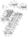
- Figures 1 to 3 show embodiments of a modular electrical part 10 of a not shown, the valves with the valve actuators and a pneumatic one Comprehensive base rail for the supply and discharge of a pressure medium Valve blocks.
- This for the central supply and / or control of the Valve block associated valves serving modular electrical Part 10 contains three basic modules 10a, 10b, 10c.
- This Basic modules 10a, 10b, 10c each have one on two opposite Open housing 10a ', 10b', 10c ', in each of which a circuit board 32 with at least a connection contact 36 (see also Fig. 4) used is.
- each connection contact 36 is one assigned opening 21 provided in a housing wall 38, the relevant contact and a zero conductor contact expediently opposite.
- a respective breakthrough 21 also several connection contacts 36 opposite one another with an assigned neutral conductor contact, to connect impulse valves in particular to be able to have two connections. A relevant one The valve is then through the associated opening 21 to the relevant number of assigned connection contacts 36 can be connected.
- the left basic module 10a is the same with two larger ones Breakthroughs 21, the middle basic module 10b with four breakthroughs 21 of the same size and the right basic module 10c with six openings 21 provided which are smaller than the openings of the previous modules, but among themselves are the same size. These openings 21 each serve as a slot for a relevant valve.
- the basic modules 10a, 10b, 10c also each have one LED display 20 to show the function.
- the left basic module 10a is also with connections 19 for an electrical Connection of the valve drives to the relevant circuit board 32 provided. Are on the top of this basic module 10a further openings 25 are provided through the electrical supply lines can be brought out.
- This modular electrical shown in Figures 1 to 3 Part 10 also contains one of the central supplies and / or control connection module 12, 13, 14 and at least one blind termination module 11, 15 for the left or the right side of a respective module row.
- the modules 10a, 10b, 10c; 12, 13, 14; 11, 15 have one same cross-sectional shape. If necessary, they are under Establishment of respective electrical interconnections or an end-face blind termination can be strung together and releasably connectable.
- the modules each releasably via a snap connection 22-24 get connected.
- These snap connections each contain a tongue 22 with a locking lug 23 and one with this Latch cooperating projection 24 on the adjacent Module. While the blanking modules intended for the left side 11 in the illustrated embodiments are only provided with tongues 22 and locking lugs 23 the right blind termination elements 15 and the electrical Connection elements 12 and 13 each only with projections 24 Mistake.
- Each basic module 10a, 10b, 10c can be described in a description Way have free electrical outputs that supplied and / or controlled via a connection module 12, 13, 14 become.
- connection module 13 the embodiment shown in Fig. 2 around a multi-pole Connector 13, which is provided with a multipole connector 28 is. 3 is for electrical supply and / or control of the valves and, if applicable, the free ones electrical outputs associated with a fieldbus module 29
- Connection module 14 provided, which in turn in the manner of a Basic module contain an inserted circuit board 50 and can be formed with tongues 22 and locking lugs 23, wherein this connection module 14, for example, by a blind termination module 15 can be completed externally.
- the Fieldbus module 29 is provided with a cover 31 on which a bus connector 30 is attached.
- the Actuation of the valves required electrical signals controlled externally.
- the respective connection module 12, 13, 14 for electrical supply and / or control of the valves and possibly the free electrical outputs basically also contain a small controller. Further is conceivable, several containing a respective small controller To connect connection modules.
- the Feedback module 18 each with an electrical feedback connection module 17 or 16 connectable.
- the feedback connection module 17 of the embodiment shown in Fig. 2 is also as the connection module 13 in turn as a multi-pin plug formed with a multipole connector 28 and projections 24.
- the feedback connection module shown in FIG. 3 has 16 again in general the form of a basic module on the one hand with projections 24 and on the other hand with tongues 22 provided housing, in turn one Printed circuit board 52 is inserted.
- the feedback module 18 shown in FIGS. 2 and 3 has in the manner of a basic module also one on two opposite End faces open housing 18 ', in the a circuit board 40 with one or more contacts is used is.
- the contacts are one in one Housing side wall 42 provided connection 44 for in particular Sensors connectable.
- the feedback module 18 and the respective feedback connection module 16 or 17 and the associated blind termination modules 11, 15 in turn a same cross-sectional shape, so that if necessary, under Establishment of respective electrical interconnections or an end-face blind termination can be strung together and via the snap connections 22-24 by plugging together are releasably connectable.
- connections 44 can be made using circular plug connections, Screw terminals or any other type of electrical connection be educated.
- the feedback module 18 and the feedback connection modules 16, 17 the same cross-sectional shape as that Basic modules 10a, 10b, 10c or a module that can be added to them Connection module 12, 13, 14, which one of each Basic module series and that of a respective feedback module series assigned blind termination modules 11, 15 formed gleiqh and are therefore interchangeable.
- connection between the vertically one above the other Modules such as between a basic module 10a, 10b, 10c and the feedback module 18 are advantageously carried out via the connecting elements 26 and not shown Screws.
- the modular electrical part can expediently for Use in a suitable for protection class IP 20 or IP 65 Valve block must be designed.
- the housing of each Components of the electrical part are preferably made made of plastic. In principle, however, other suitable ones are also Materials conceivable.
Landscapes
- Engineering & Computer Science (AREA)
- Physics & Mathematics (AREA)
- Fluid Mechanics (AREA)
- Mechanical Engineering (AREA)
- General Engineering & Computer Science (AREA)
- Microelectronics & Electronic Packaging (AREA)
- Magnetically Actuated Valves (AREA)
- Programmable Controllers (AREA)
- Valve Housings (AREA)
- Coupling Device And Connection With Printed Circuit (AREA)
- Connections Arranged To Contact A Plurality Of Conductors (AREA)
- External Artificial Organs (AREA)
- Portable Nailing Machines And Staplers (AREA)
- Connector Housings Or Holding Contact Members (AREA)
Description
- Fig. 1
- eine schematische auseinandergezogene Darstellung eines elektrischen Teils eine Ventilblocks mit drei elektrischen Grundmodulen, einem elektrischen Anschlußmodul und einem Blindabschlußmodul,
- Fig. 2
- eine schematische auseinandergezogene Darstellung eines elektrischen Teils eines Ventilblocks mit einem zusätzlichen Rückmeldemodul, dem wiederum ein elektrischer Anschlußmodul sowie ein Blindabschlußmodul zugeordnet sind,
- Fig. 3
- eine schematische auseinandergezogene Darstellung eines elektrischen Teils eines Ventilblocks mit einem an die Grundmodulreihe anschließbaren Feldbusmodul, und
- Fig. 4
- eine schematische Darstellung zur Erläuterung des Prinzips des Leiterbahnverlaufs auf den verschiedenen Leiterplatten.
Claims (20)
- Modularer elektrischer Teil zur zentralen Versorgung und/oder Ansteuerung von einem Ventilblock zugeordneten Ventilen, dadurch gekennzeichnet, daß er wenigstens einen Grundmodul (10a, 10b, 10c) enthält, der ein an zwei gegenüberliegenden Stirnseiten offenes Gehäuse (10a', 10b', 10c') besitzt, in das eine Leiterplatte (32) mit einem oder mehreren Anschlußkontakten (36) eingesetzt ist, wobei eine Gehäuseseitenwandung (38) mit wenigstens einem Durchbruch (21) versehen ist, durch den hindurch ein betreffendes Ventil oder irgendein anderer Aktor an wenigstens einen zugeordneten Anschlußkontakt (36) anschließbar ist, und wenigstens einen der zentralen Versorgung und/oder Ansteuerung dienenden Anschlußmodul (12, 13, 14) sowie wenigstens einen Blindabschlußmodul (11, 15) enthält, und daß die Module (10a, 10b, 10c; 12, 13, 14; 11, 15) eine gleichartige Querschnittsform besitzen, bedarfsweise unter Herstellung von jeweiligen elektrischen Zwischenverbindungen bzw. eines stirnseitigen Blindabschlusses aneinanderreihbar und lösbar miteinander verbindbar sind.
- Modularer elektrischer Teil nach Anspruch 1, dadurch gekennzeichnet, daß die Module (10a, 10b, 10c; 12, 13, 14; 11, 15) jeweils über eine Schnappverbindung (22-24) lösbar miteinander verbindbar sind.
- Modularer elektrischer Teil nach Anspruch 1 oder 2, dadurch gekennzeichnet, daß Grundmodule (10a, 10b, 10c) mit einer unterschiedlichen Anzahl von Anschlußkontakten (36) und zugeordneten Durchbrüchen (21) vorgesehen sind.
- Modularer elektrischer Teil nach einem der vorhergehenden Ansprüche, dadurch gekennzeichnet, daß Grundmodule (10a, 10b, 10c) mit Durchbrüchen (21) unterschiedlicher Anzahl und/oder Größe vorgesehen sind.
- Modularer elektrischer Teil nach einem der vorhergehenden Ansprüche, dadurch gekennzeichnet, daß der Grundmodul (10a, 10b, 10c) freie elektrische Ausgänge aufweist, die über ein Anschlußmodul (12, 13, 14) versorgt und/oder angesteuert sind.
- Modularer elektrischer Teil nach einem der vorhergehenden Ansprüche, dadurch gekennzeichnet, daß er wenigstens einen bedarfsweise auf einen jeweiligen Grundmodul (10a, 10b, 10c) aufsetzbaren, lösbar mit diesem verbindbaren Rückmeldemodul (18) enthält, der die Ventile betreffende Rückmeldesignale liefert.
- Modularer elektrischer Teil nach Anspruch 6, dadurch gekennzeichnet, daß er wenigstens einen unter Herstellung von jeweiligen elektrischen Zwischenverbindungen bedarfsweise an den Rückmeldemodul (18) anreihbaren und lösbar mit diesem verbindbaren Rückmeldeanschlußmodul (16, 17) enthält.
- Modularer elektrischer Teil nach einem der vorhergehenden Ansprüche, dadurch gekennzeichnet, daß zur elektrischen Versorgung und/oder Ansteuerung der Ventile und gegebenenfalls der freien elektrischen Ausgänge ein Null- und Schutzleiteranschlüsse (27) aufweisender Anschlußmodul (12) vorgesehen ist.
- Modularer elektrischer Teil nach einem der vorhergehenden Ansprüche, dadurch gekennzeichnet, daß als Anschlußmodul zur elektrischen Versorgung und/oder Ansteuerung der Ventile und gegebenenfalls der freien elektrischen Ausgänge und/oder als Rückmeldeanschlußmodul ein mehrpoliger Stecker (13, 17) vorgesehen ist.
- Modularer elektrischer Teil nach einem der vorhergehenden Ansprüche, dadurch gekennzeichnet, daß zur elektrischen Versorgung und/oder Ansteuerung der Ventile und gegebenenfalls der freien elektrischen Ausgänge ein einem Feldbusmodul (29) zugeordneter Anschlußmodul (14) vorgesehen ist.
- Modularer elektrischer Teil nach einem der vorhergehenden Ansprüche, dadurch gekennzeichnet, daß der Anschlußmodul (14) zur elektrischen Versorgung und/oder Ansteuerung der Ventile und gegebenenfalls der freien elektrischen Ausgänge eine Kleinsteuerung enthält.
- Modularer elektrischer Teil nach Anspruch 11, dadurch gekennzeichnet, daß mehrere eine jeweilige Kleinsteuerung enthaltende Anschlußmodule (14) vorgesehen sind.
- Modularer elektrischer Teil nach einem der vorhergehenden Ansprüche, dadurch gekennzeichnet, daß ein oder mehrere Anschlußmodule (12, 13) vorgesehen sind, die Verbindungen zu externen Steuerungen bilden.
- Modularer elektrischer Teil nach einem der vorhergehenden Ansprüche 7 bis 13, dadurch gekennzeichnet, daß der Rückmeldemodul (18) ein an zwei gegenüberliegenden Stirnseiten offenes Gehäuse (18') besitzt, in das eine Leiterplatte (40) mit einem oder mehreren Kontakten eingesetzt ist, die jeweils mit einem in einer Gehäuseseitenwandung (42) vorgesehenen Anschluß (44) verbindbar sind, und daß der Rückmeldemodul (18), der Rückmeldeanschlußmodul (16, 17) und zugeordnete Blindabschlußmodule (11, 15) eine gleiche Querschnittsform besitzen, bedarfsweise unter Herstellung von jeweiligen elektrischen Zwischenverbindungen bzw. eines stirnseitigen Blindabschlusses aneinanderreihbar und lösbar miteinander verbindbar sind.
- Modularer elektrischer Teil nach einem der vorhergehenden Ansprüche 7 bis 14, durch gekennzeichnet, daß der Rückmeldemodul (18) und der Rückmeldeanschlußmodul (16, 17) die gleiche Querschnittsform wie der Grundmodul (10a, 10b, 10c) bzw. ein an diesen anreihbarer Anschlußmodul (13, 14) besitzen und daß zumindest die einer jeweiligen Grundmodulreihe und die einer jeweiligen Rückmeldemodulreihe zugeordneten Blindabschlußmodule (11, 15) gleich ausgebildet und somit austauschbar sind.
- Modularer elektrischer Teil nach einem der vorhergehenden Ansprüche, dadurch gekennzeichnet, daß einem Durchbruch (21) jeweils wenigstens ein Anschlußkontakt (36) und ein Null-Leiterkontakt gegenüberliegt.
- Modularer elektrischer Teil nach einem der Ansprüche 1 bis 15, dadurch gekennzeichnet, daß einem Durchbruch (21) für den Anschluß eines Impulsventils oder dergleichen jeweils wenigstens zwei Anschlußkontakte (36) gegenüberliegen.
- Modularer elektrischer Teil nach einem der vorhergehenden Ansprüche, dadurch gekennzeichnet, daß die den Grundmodulen (10a, 10b, 10c) und/oder Rückmeldemodulen (18) zugeordneten Leiterplatten (32, 40) eine gleiche Anzahl von zumindest abschnittsweise zueinander parallelen Leiterbahnen (35) aufweisen, die ausgehend von einem eingangsseitigen Plattenrand (46) zu dem gegenüberliegenden ausgangsseitigen Plattenrand (48) geführt bzw. seitlich zu Anschlußkontakten (36) abgezweigt sind, wobei die einem Ende (46') des eingangseitigen Plattenrandes (46) am nächsten gelegenen Leiterbahnen beginnend mit der dem Ende (46') benachbarten Bahn aufeinanderfolgend in einer der Anzahl der Anschlußkontakte (36) entsprechenden Anzahl zu den Anschlußkontakten (36) geführt sind, während die verbleibenden Leiterbahnen am ausgangsseitigen Plattenrand (48) so versetzt sind, daß sie mit den dem einen Ende (46') des eingangseitigen Plattenrandes (46) am nächsten gelegenen Leiterbahnabschnitten ausgerichtet sind.
- Modularer elektrischer Teil nach einem der vorhergehenden Ansprüche, dadurch gekennzeichnet, daß er einem für die Schutzart IP 20 ausgelegten Ventilblock zugeordnet ist.
- Modularer elektrischer Teil nach einem der vorhergehenden Ansprüche, dadurch gekennzeichnet, daß er einem für die Schutzart IP 65 ausgelegten Ventilblock zugeordnet ist.
Applications Claiming Priority (2)
| Application Number | Priority Date | Filing Date | Title |
|---|---|---|---|
| DE29507119U DE29507119U1 (de) | 1995-04-27 | 1995-04-27 | Modularer elektrischer Teil für einen Ventilblock |
| DE29507119U | 1995-04-27 |
Publications (2)
| Publication Number | Publication Date |
|---|---|
| EP0740082A1 EP0740082A1 (de) | 1996-10-30 |
| EP0740082B1 true EP0740082B1 (de) | 2000-08-16 |
Family
ID=8007383
Family Applications (1)
| Application Number | Title | Priority Date | Filing Date |
|---|---|---|---|
| EP19960106421 Expired - Lifetime EP0740082B1 (de) | 1995-04-27 | 1996-04-24 | Modularer elektrischer Teil für einen Ventilblock |
Country Status (5)
| Country | Link |
|---|---|
| US (1) | US5883785A (de) |
| EP (1) | EP0740082B1 (de) |
| JP (2) | JP3782826B2 (de) |
| DE (2) | DE29507119U1 (de) |
| WO (1) | WO1996034208A1 (de) |
Families Citing this family (13)
| Publication number | Priority date | Publication date | Assignee | Title |
|---|---|---|---|---|
| DE19722925C1 (de) * | 1997-05-27 | 1998-09-10 | Mannesmann Ag | Elektrisches Anschlußelement für Elektromagnete von Ventileinheiten |
| JP3388718B2 (ja) * | 1999-08-03 | 2003-03-24 | エスエムシー株式会社 | シリアル−パラレル信号変換入出力装置 |
| US6449164B1 (en) * | 2002-01-22 | 2002-09-10 | Jack Gershfeld | Enclosure for housing a printed circuit board |
| DE102004005982B3 (de) * | 2004-02-06 | 2005-06-30 | Festo Ag & Co. | Druckluftwartungsvorrichtung |
| DE102004018115B4 (de) * | 2004-04-14 | 2011-09-15 | Siemens Ag | Baugruppe mit zwei Teilkomponenten sowie Dichtungsmodul |
| DE502004002536D1 (de) * | 2004-04-16 | 2007-02-15 | Festo Ag & Co | Proportionalventil-Baukasten und damit hergestelltes Proportionalventil |
| JP2007165048A (ja) * | 2005-12-12 | 2007-06-28 | Smc Corp | 信号入出力装置 |
| DE102006051281C5 (de) * | 2006-10-25 | 2013-04-25 | Balluff Gmbh | Verteilervorrichtung |
| JP5004049B2 (ja) * | 2007-10-10 | 2012-08-22 | Smc株式会社 | 空気圧機器用制御システム |
| EP2110562B1 (de) * | 2008-04-15 | 2011-05-04 | FESTO AG & Co. KG | Ventilanordnung |
| DE102009053583B3 (de) * | 2009-11-17 | 2011-03-31 | Semikron Elektronik Gmbh & Co. Kg | Modular aufgebaute Stromrichteranordnung |
| US9478927B1 (en) * | 2015-04-29 | 2016-10-25 | Yang Ji Co., Ltd. | Expandable power adaptor |
| CN106016640A (zh) * | 2016-07-11 | 2016-10-12 | 广东美的暖通设备有限公司 | 用于空调器的电控盒组件及具有其的空调器 |
Family Cites Families (20)
| Publication number | Priority date | Publication date | Assignee | Title |
|---|---|---|---|---|
| DE2646616C3 (de) * | 1976-10-15 | 1980-08-07 | C. A. Weidmueller Kg, 4930 Detmold | Anreihbares Einbauteil |
| US4399836A (en) * | 1981-04-14 | 1983-08-23 | Marotta Scientific Controls, Inc. | Self-contained closed-loop electrically operated valve |
| US4401351A (en) * | 1981-09-28 | 1983-08-30 | Advant Corporation | Expandable card cage |
| FR2569899B1 (fr) * | 1984-09-06 | 1986-09-05 | Alsthom Cgee | Boitier modulaire pour appareillage electrique et modules correspondants |
| DE3633785A1 (de) * | 1986-10-03 | 1988-04-07 | Siemens Ag | Automatisierungsgeraet |
| EP0235320A1 (de) * | 1986-02-28 | 1987-09-09 | C.A. Weidmüller GmbH & Co. | Anreihbares Einbaugehäuse |
| FR2612358B1 (fr) * | 1986-12-17 | 1994-08-05 | Aerospatiale | Dispositif electronique constitue d'une pluralite de modules alignes et juxtaposes |
| JPH0313991Y2 (de) * | 1986-12-29 | 1991-03-28 | ||
| DE3910913C2 (de) * | 1989-04-05 | 1997-02-27 | Festo Kg | Pneumatische oder hydraulische Ventileinheit |
| DE3917528A1 (de) * | 1989-05-30 | 1990-12-06 | Kloeckner Becorit Gmbh | Vorrichtung zur elektrischen ansteuerung einer reihe von magnetventilen, insbesondere fuer die verwendung im untertaegigen grubenbetrieb |
| DE4020791C1 (de) * | 1990-06-28 | 1991-06-06 | Mannesmann Ag, 4000 Duesseldorf, De | |
| US5128830A (en) * | 1990-07-02 | 1992-07-07 | Digital Equipment Corporation | Integrated installation assembly with self aligning connector |
| CH683021A5 (de) * | 1991-06-25 | 1993-12-31 | Walter Ag | Anordnung mit mehreren Magnetventilen, insbesondere für eine Ventilbatterie. |
| DE4143274C2 (de) * | 1991-12-27 | 1994-03-10 | Mannesmann Ag | Ventilbaugruppe in Modulbauweise |
| DE4222637C2 (de) * | 1992-07-10 | 1998-12-10 | Festo Ag & Co | Ventilanordnung |
| CH686975A5 (de) * | 1993-01-06 | 1996-08-15 | Imi Norgren Ag | Fluidische Ventileinheit. |
| DE9305574U1 (de) * | 1993-04-14 | 1993-06-17 | Herion-Werke Kg, 7012 Fellbach | Steuervorrichtung für Elektromagnetventile |
| US5619013A (en) * | 1993-12-17 | 1997-04-08 | Hubbell Incorporated | Gangable electrical box |
| DE4343958A1 (de) * | 1993-12-22 | 1995-07-13 | Hirschmann Richard Gmbh Co | Tragekörper für elektrisch ansteuerbare Ventile |
| DE9406393U1 (de) * | 1994-04-20 | 1994-07-07 | Kuhnke GmbH, 23714 Malente | Modular aufgebauter Trägerblock für elektromagnetische Wegeventile |
-
1995
- 1995-04-27 DE DE29507119U patent/DE29507119U1/de not_active Expired - Lifetime
-
1996
- 1996-04-24 WO PCT/EP1996/001709 patent/WO1996034208A1/de not_active Ceased
- 1996-04-24 DE DE59605742T patent/DE59605742D1/de not_active Expired - Lifetime
- 1996-04-24 EP EP19960106421 patent/EP0740082B1/de not_active Expired - Lifetime
- 1996-04-24 US US08/750,564 patent/US5883785A/en not_active Expired - Lifetime
- 1996-04-24 JP JP53216396A patent/JP3782826B2/ja not_active Expired - Fee Related
-
2005
- 2005-09-05 JP JP2005256924A patent/JP2006100269A/ja active Pending
Also Published As
| Publication number | Publication date |
|---|---|
| JP2006100269A (ja) | 2006-04-13 |
| WO1996034208A1 (de) | 1996-10-31 |
| JPH10502725A (ja) | 1998-03-10 |
| EP0740082A1 (de) | 1996-10-30 |
| DE29507119U1 (de) | 1995-07-20 |
| US5883785A (en) | 1999-03-16 |
| JP3782826B2 (ja) | 2006-06-07 |
| DE59605742D1 (de) | 2000-09-21 |
Similar Documents
| Publication | Publication Date | Title |
|---|---|---|
| EP0895708B1 (de) | Modulares, baugruppenweise erweiterbares peripheriegerät mit selbstaufbauender elektrischer verbindung | |
| EP0709932B1 (de) | Modulare Steuerungsanlage mit Busleiter z. B. zur Gebäudeautomatisierung | |
| EP0712267B1 (de) | Modulare Steuerungsanlage mit integriertem Feldbusanschluss | |
| DE69816236T2 (de) | Schnittstellenvorrichtung zwischen Teilen einer Anlage | |
| EP0710064B1 (de) | Feldbusanschlussmodul | |
| DE2414566C2 (de) | Elektrisches Automatiksystem | |
| EP1174781B1 (de) | Einrichtung zur Signalübertragung | |
| EP2742785B1 (de) | Modulare steuerungsvorrichtung | |
| EP2742390B1 (de) | Modulare steuerungsvorrichtung | |
| EP0709933A2 (de) | Modulare Steuerungsanlage mit Busleiter | |
| DE212016000059U1 (de) | An einer Schiene anbringbares Steuersystem mit verbesserter Anbringung | |
| DE3504712A1 (de) | Elektronischer reglerbaustein und regelvorrichtung in modulbauweise | |
| DE4437316C2 (de) | Dezentrale Ein/Ausgabebaugruppe für elektronische Steuerungen | |
| EP0740082A1 (de) | Modularer elektrischer Teil für einen Ventilblock | |
| DE19714868C2 (de) | Busfähige elektrische Koppeleinheit | |
| DE202006006659U1 (de) | Elektrisches oder elektronisches Gerät | |
| EP0895707A1 (de) | Modulares, baugruppenweise erweiterbares peripheriegerät mit selbsttragendem aufbau | |
| DE3943752C2 (de) | Pneumatische oder hydraulische Ventileinheit | |
| WO1998024153A1 (de) | Einrichtung zur codierung von steckplätzen | |
| EP1564848B1 (de) | Installationsgerät mit kodierbarer Steckschnittstelle und entsprechendes Zusatzmodul | |
| EP3660603B1 (de) | Busfähiges aneinanderreihbares funktionsmodul | |
| EP2769396A1 (de) | Elektronikgehäuse für schaltgeräte, insbesondere für niederspannungsschaltgeräte | |
| DE2907207A1 (de) | Umschaltsteckverbindung | |
| EP0585548A1 (de) | Feldstation für ein von einem Steuercomputer gesteuertes serielles Bussystem | |
| EP0457254A2 (de) | Vorrichtung zur Halterung elektrotechnischer, insbesondere nachrichtentechnischer Bauteile |
Legal Events
| Date | Code | Title | Description |
|---|---|---|---|
| PUAI | Public reference made under article 153(3) epc to a published international application that has entered the european phase |
Free format text: ORIGINAL CODE: 0009012 |
|
| AK | Designated contracting states |
Kind code of ref document: A1 Designated state(s): CH DE FR GB IT LI |
|
| 17P | Request for examination filed |
Effective date: 19970430 |
|
| GRAG | Despatch of communication of intention to grant |
Free format text: ORIGINAL CODE: EPIDOS AGRA |
|
| 17Q | First examination report despatched |
Effective date: 19990805 |
|
| GRAG | Despatch of communication of intention to grant |
Free format text: ORIGINAL CODE: EPIDOS AGRA |
|
| GRAH | Despatch of communication of intention to grant a patent |
Free format text: ORIGINAL CODE: EPIDOS IGRA |
|
| GRAH | Despatch of communication of intention to grant a patent |
Free format text: ORIGINAL CODE: EPIDOS IGRA |
|
| GRAA | (expected) grant |
Free format text: ORIGINAL CODE: 0009210 |
|
| AK | Designated contracting states |
Kind code of ref document: B1 Designated state(s): CH DE FR GB IT LI |
|
| REG | Reference to a national code |
Ref country code: CH Ref legal event code: NV Representative=s name: TROESCH SCHEIDEGGER WERNER AG Ref country code: CH Ref legal event code: EP |
|
| REF | Corresponds to: |
Ref document number: 59605742 Country of ref document: DE Date of ref document: 20000921 |
|
| ITF | It: translation for a ep patent filed | ||
| GBT | Gb: translation of ep patent filed (gb section 77(6)(a)/1977) |
Effective date: 20000907 |
|
| ET | Fr: translation filed | ||
| PLBE | No opposition filed within time limit |
Free format text: ORIGINAL CODE: 0009261 |
|
| STAA | Information on the status of an ep patent application or granted ep patent |
Free format text: STATUS: NO OPPOSITION FILED WITHIN TIME LIMIT |
|
| 26N | No opposition filed | ||
| REG | Reference to a national code |
Ref country code: GB Ref legal event code: IF02 |
|
| PGFP | Annual fee paid to national office [announced via postgrant information from national office to epo] |
Ref country code: CH Payment date: 20090417 Year of fee payment: 14 |
|
| PGFP | Annual fee paid to national office [announced via postgrant information from national office to epo] |
Ref country code: GB Payment date: 20090421 Year of fee payment: 14 |
|
| REG | Reference to a national code |
Ref country code: CH Ref legal event code: PFA Owner name: BUERKERT WERKE GMBH Free format text: BUERKERT WERKE GMBH & CO.#CHRISTIAN-BUERKERT-STRASSE 13-17#D-74653 INGELFINGEN (DE) -TRANSFER TO- BUERKERT WERKE GMBH#CHRISTIAN-BUERKERT-STRASSE 13-17#74653 INGELFINGEN (DE) |
|
| REG | Reference to a national code |
Ref country code: GB Ref legal event code: 732E Free format text: REGISTERED BETWEEN 20100422 AND 20100428 |
|
| REG | Reference to a national code |
Ref country code: FR Ref legal event code: TP Ref country code: FR Ref legal event code: CJ Ref country code: FR Ref legal event code: CD |
|
| REG | Reference to a national code |
Ref country code: CH Ref legal event code: PL |
|
| GBPC | Gb: european patent ceased through non-payment of renewal fee |
Effective date: 20100424 |
|
| PG25 | Lapsed in a contracting state [announced via postgrant information from national office to epo] |
Ref country code: LI Free format text: LAPSE BECAUSE OF NON-PAYMENT OF DUE FEES Effective date: 20100430 Ref country code: CH Free format text: LAPSE BECAUSE OF NON-PAYMENT OF DUE FEES Effective date: 20100430 |
|
| PG25 | Lapsed in a contracting state [announced via postgrant information from national office to epo] |
Ref country code: GB Free format text: LAPSE BECAUSE OF NON-PAYMENT OF DUE FEES Effective date: 20100424 |
|
| PGFP | Annual fee paid to national office [announced via postgrant information from national office to epo] |
Ref country code: IT Payment date: 20130424 Year of fee payment: 18 Ref country code: FR Payment date: 20130515 Year of fee payment: 18 |
|
| REG | Reference to a national code |
Ref country code: FR Ref legal event code: ST Effective date: 20141231 |
|
| PG25 | Lapsed in a contracting state [announced via postgrant information from national office to epo] |
Ref country code: FR Free format text: LAPSE BECAUSE OF NON-PAYMENT OF DUE FEES Effective date: 20140430 |
|
| PG25 | Lapsed in a contracting state [announced via postgrant information from national office to epo] |
Ref country code: IT Free format text: LAPSE BECAUSE OF NON-PAYMENT OF DUE FEES Effective date: 20140424 |
|
| PGFP | Annual fee paid to national office [announced via postgrant information from national office to epo] |
Ref country code: DE Payment date: 20150415 Year of fee payment: 20 |
|
| REG | Reference to a national code |
Ref country code: DE Ref legal event code: R071 Ref document number: 59605742 Country of ref document: DE |