EP0740076A2 - Compresseur à plateau en biais à compression variable - Google Patents
Compresseur à plateau en biais à compression variable Download PDFInfo
- Publication number
- EP0740076A2 EP0740076A2 EP96105801A EP96105801A EP0740076A2 EP 0740076 A2 EP0740076 A2 EP 0740076A2 EP 96105801 A EP96105801 A EP 96105801A EP 96105801 A EP96105801 A EP 96105801A EP 0740076 A2 EP0740076 A2 EP 0740076A2
- Authority
- EP
- European Patent Office
- Prior art keywords
- piston
- swash plate
- drive shaft
- casing
- stopper portion
- Prior art date
- Legal status (The legal status is an assumption and is not a legal conclusion. Google has not performed a legal analysis and makes no representation as to the accuracy of the status listed.)
- Granted
Links
- 238000006073 displacement reaction Methods 0.000 title claims abstract description 32
- 230000033001 locomotion Effects 0.000 claims abstract description 50
- 239000003507 refrigerant Substances 0.000 description 18
- 230000002093 peripheral effect Effects 0.000 description 11
- 239000000314 lubricant Substances 0.000 description 10
- 238000010276 construction Methods 0.000 description 8
- 238000001816 cooling Methods 0.000 description 4
- 230000001965 increasing effect Effects 0.000 description 3
- 238000003754 machining Methods 0.000 description 3
- 229910000838 Al alloy Inorganic materials 0.000 description 2
- 230000005540 biological transmission Effects 0.000 description 2
- 230000006835 compression Effects 0.000 description 2
- 238000007906 compression Methods 0.000 description 2
- 238000005461 lubrication Methods 0.000 description 2
- 230000004044 response Effects 0.000 description 2
- 230000001629 suppression Effects 0.000 description 2
- 229910001018 Cast iron Inorganic materials 0.000 description 1
- 229910000831 Steel Inorganic materials 0.000 description 1
- 238000004378 air conditioning Methods 0.000 description 1
- 230000004323 axial length Effects 0.000 description 1
- 230000000694 effects Effects 0.000 description 1
- 230000006698 induction Effects 0.000 description 1
- 230000001939 inductive effect Effects 0.000 description 1
- 230000007246 mechanism Effects 0.000 description 1
- 238000000034 method Methods 0.000 description 1
- 230000004048 modification Effects 0.000 description 1
- 238000012986 modification Methods 0.000 description 1
- 238000007493 shaping process Methods 0.000 description 1
- 239000010959 steel Substances 0.000 description 1
Images


Classifications
-
- F—MECHANICAL ENGINEERING; LIGHTING; HEATING; WEAPONS; BLASTING
- F04—POSITIVE - DISPLACEMENT MACHINES FOR LIQUIDS; PUMPS FOR LIQUIDS OR ELASTIC FLUIDS
- F04B—POSITIVE-DISPLACEMENT MACHINES FOR LIQUIDS; PUMPS
- F04B27/00—Multi-cylinder pumps specially adapted for elastic fluids and characterised by number or arrangement of cylinders
- F04B27/08—Multi-cylinder pumps specially adapted for elastic fluids and characterised by number or arrangement of cylinders having cylinders coaxial with, or parallel or inclined to, main shaft axis
- F04B27/0873—Component parts, e.g. sealings; Manufacturing or assembly thereof
- F04B27/0878—Pistons
-
- F—MECHANICAL ENGINEERING; LIGHTING; HEATING; WEAPONS; BLASTING
- F05—INDEXING SCHEMES RELATING TO ENGINES OR PUMPS IN VARIOUS SUBCLASSES OF CLASSES F01-F04
- F05C—INDEXING SCHEME RELATING TO MATERIALS, MATERIAL PROPERTIES OR MATERIAL CHARACTERISTICS FOR MACHINES, ENGINES OR PUMPS OTHER THAN NON-POSITIVE-DISPLACEMENT MACHINES OR ENGINES
- F05C2253/00—Other material characteristics; Treatment of material
- F05C2253/12—Coating
-
- Y—GENERAL TAGGING OF NEW TECHNOLOGICAL DEVELOPMENTS; GENERAL TAGGING OF CROSS-SECTIONAL TECHNOLOGIES SPANNING OVER SEVERAL SECTIONS OF THE IPC; TECHNICAL SUBJECTS COVERED BY FORMER USPC CROSS-REFERENCE ART COLLECTIONS [XRACs] AND DIGESTS
- Y10—TECHNICAL SUBJECTS COVERED BY FORMER USPC
- Y10T—TECHNICAL SUBJECTS COVERED BY FORMER US CLASSIFICATION
- Y10T74/00—Machine element or mechanism
- Y10T74/18—Mechanical movements
- Y10T74/18056—Rotary to or from reciprocating or oscillating
- Y10T74/18296—Cam and slide
- Y10T74/18336—Wabbler type
Definitions
- the present invention relates to variable displacement swash plate type compressors for use in an automotive air conditioning system or the like, and more particularly to such compressors of a type which is improved in a mechanism for suppressing undesired play of pistons installed therein.
- variable displacement swash plate type compressor In automotive air conditioners, a so-called “variable displacement swash plate type compressor” is widely used, which can adjust the amount of compressed refrigerant discharged therefrom.
- variable displacement swash plate type compressors there is a type which generally comprises a drive shaft driven by a power plant such as an automotive engine, and a swash plate mounted on the drive shaft in a manner to be inclinable to the same.
- a power plant such as an automotive engine
- the swash plate carries out so-called “spiral turns" about the axis of the drive shaft.
- the compressor further comprises a plurality of cylinder chambers and a plurality of pistons slidably received in the cylinder chambers. Each piston is directly, but slidably engaged with the swash plate.
- each piston employed therein comprises a piston head portion which moves in the corresponding cylinder chamber, and a generally U-shaped base portion which is slidably engaged with the swash plate.
- a piston head portion which moves in the corresponding cylinder chamber
- a generally U-shaped base portion which is slidably engaged with the swash plate.
- two semi-spherical bearing shoes are used which are installed in a recess of the U-shaped base portion having a peripheral portion of the swash plate slidably put therebetween.
- Opposed walls defined in the recess of the U-shaped base portion have spherical recesses with which spherical outer surfaces of the two bearing shoes are slidably engaged, and upper and lower flat walls of the peripheral portion of the swash plate are slidably engaged with respective inner flat surfaces of the two semi-spherical bearing shoes.
- the pistons are forced to make reciprocative movements relative to the cylinder chambers with different but subsequent cycles. That is, when, under rotation of the swash plate, the peripheral portion of the same comes to the nearest position to one cylinder chamber, the corresponding piston assumes its top dead point (TDP), while, when the peripheral portion comes to the farmost position to the cylinder chamber, the piston assumes its bottom dead position (BDP). That is, the spiral turns of the swash plate induce reciprocative movements of the pistons in the cylinder chambers.
- TDP top dead point
- BDP bottom dead position
- a refrigerant is introduced through an inlet port into the compressor and compressed by the pistons in the cylinder chambers and then discharged through an output port to the outside.
- Fig. 16 shows a view taken from an axially rear position of one piston 123.
- the piston 123 has on its outer surface an axially extending ridge 124, and the casing 112 has at its inner wall an axially extending groove 127 which slidably receives the ridge 124 of the piston 123. With this arrangement, the undesired turning movement of the piston 123 is suppressed.
- a convex surface 134 which faces a cylindrical inner surface of the casing 112 with a slight clearance left therebetween.
- the radius of curvature "R 1 " of the convex surface 134 is larger than that "R p " of the cylindrical outer surface of a major part of the piston 133, but smaller than that "R 2 " of the cylindrical inner surface of the casing 112. This dimensional relationship seems to be provided for achieving a so-called “surface-to-surface contact” between the convex surface 134 and the cylindrical inner surface of the casing 112 upon the turning movement of the piston 133.
- a variable displacement swash plate type compressor which comprises a casing having a plurality of cylinder chambers circumferentially arranged therein; a plurality of pistons incorporated with the cylinder chambers respectively; a drive shaft extending in the casing; a swash plate disposed on the drive shaft and inclinable relative to the same; means for causing the swash plate to make spiral turns when the drive shaft is rotated; means for achieving a hinged connection between the swash plate and each of the pistons to make a reciprocative movement of each piston when the drive shaft is rotated; and a structure for minimizing a turning movement of each piston about its axis.
- the structure includes a given part of the piston which is always out of the corresponding cylinder chamber; a turn stopper portion formed on the given part, the turn stopper portion including laterally opposed sides each having a rounded outer surface; and means defining a cylindrical surface in the casing at a portion which faces the turn stopper portion, the cylindrical surface being so constructed and arranged as to make a surface-to-surface contact with one of the laterally opposed sides when the piston is turned about its axis by a given angle.
- a variable displacement swash plate type compressor which comprises a casing having a plurality of cylinder chambers circumferentially arranged therein; a plurality of pistons incorporated with the cylinder chambers respectively; a drive shaft extending in the casing; a swash plate disposed on the drive shaft and inclinable relative to the same; means for causing the swash plate to make spiral turns when the drive shaft is rotated; means for achieving a hinged connection between the swash plate and each of the pistons to make a reciprocative movement of each piston when the drive shaft is rotated; and a structure for minimizing a turning movement of each piston about its axis.
- the structure includes a given part of the piston which is always out of the corresponding cylinder chamber; a turn stopper portion formed on the given part, the turn stopper portion including a major part which has a rounded outer surface and laterally opposed sides each having a rounded outer surface; and means defining a cylindrical surface in the casing at a portion which faces the turn stopper portion, the cylindrical surface being so arranged as to make a surface-to-surface contact with one of the laterally opposed sides when the piston is turned about its axis by a given angle.
- a variable displacement swash plate type compressor which comprises a casing having a plurality of cylinder chambers circumferentially arranged therein; a plurality of pistons incorporated with the cylinder chambers respectively; a drive shaft extending in the casing; a swash plate disposed on the drive shaft and inclinable relative to the same; means for causing the swash plate to make spiral turns when the drive shaft is rotated; means for achieving a hinged connection between the swash plate and each of the pistons to make a reciprocative movement of each piston when the drive shaft is rotated; and a structure for minimizing a turning movement of each piston about its axis.
- the structure includes a given part of the piston which is always out of the corresponding cylinder chamber; a turn stopper portion formed on the given part, the turn stopper portion including a major part which has a rounded outer surface; a cylindrical surface defined by an inner wall of the casing at a position which faces the turn stopper portion, the cylindrical surface including two parallel bank portions which extend axially and have each a cylindrical top surface, and means which defines an axially extending groove between the two parallel bank portions, the cylindrical top surface of each bank portion being so arranged as to make a surface-to-surface contact with the rounded outer surface of the major part of the turn stopper portion when the piston is turned about its axis by a given angle.
- a variable displacement swash plate type compressor which comprises a casing having a plurality of cylinder chambers circumferentially arranged therein; a plurality of pistons incorporated with the cylinder chambers respectively; a drive shaft extending in the casing; a swash plate disposed on the drive shaft and inclinable relative to the same; means for causing the swash plate to make spiral turns when the drive shaft is rotated; means for achieving a hinged connection between the swash plate and each of the pistons to make a reciprocative movement of each piston when the drive shaft is rotated; and a structure for minimizing a turning movement of each piston about its axis.
- the structure includes a given part of the piston which is always out of the corresponding cylinder chamber; a turn stopper portion formed on the given part, the turn stopper portion including a major part which has a rounded outer surface, laterally opposed rounded sides and axially opposed rounded sides; means defining a cylindrical surface in the casing at a portion which faces the turn stopper portion, the cylindrical surface being so arranged as to make a surface-to-surface contact with one of the laterally opposed rounded sides when the piston is turned about its axis by a given angle and so arranged as to make a surface-to-surface contact with one of the axially opposed rounded sides when the piston is subjected to a pitching motion.
- a variable displacement swash plate type compressor of a first embodiment of the present invention which is generally denoted by numeral 10A.
- the compressor 10A comprises a cylindrical casing 12 and first and second heads 14 and 16 secured to axially opposed open ends of the casing 12. These three members are united tightly by means of bolts (not shown). Within the casing 12, there are defined a plurality of cylinder chambers 18 and a crank chamber 20.
- the first head 14 is connected to the casing 12 through a valve sheet 22.
- the valve sheet 22 is provided with intake valves (not shown) and discharge valves (not shown). These intake and discharge valves are circumferentially arranged at evenly spaced intervals on the valve sheet 22.
- Designated by numeral 24 is a valve body possessed by one of the discharge valves.
- a drive shaft 26 extends axially in the casing 12.
- the drive shaft 26 has an extension which pierces the second head 16 to be exposed to the outside.
- a bearing 40 is held in the second head 16 to bear the drive shaft 26.
- a pulley 28 is disposed on the exposed part of the drive shaft 26 through an electromagnetic clutch 30.
- a transmission belt driven by an engine is put on the pulley 28.
- the cylinder chambers 18 are circumferentially arranged in the casing 12 at evenly spaced intervals.
- the cylinder chambers 18 are the same in construction and have respective pistons 32 slidably disposed therein.
- the pistons 32 are the same in construction.
- Each piston 32 comprises a piston head portion 32a which is slidably disposed in the corresponding cylinder chamber 18 and a generally U-shaped base portion 32b which is always out of the cylinder chamber 18.
- the U-shaped base portion 32b is engaged with a peripheral portion of a swash plate 34 through two semi-spherical bearing shoes 36 and 38.
- Opposed walls defined in a recess of the U-shaped base portion 32b of the piston 32 have spherical recesses 32c and 32d into which spherical outer portions of the two bearing shoes 36 and 38 are slidably received, and opposed flat walls of the two bearing shoes 36 and 38 slidably put therebetween the peripheral flat portion of the swash plate 34.
- the swash plate 34 is formed with a balancer 34a.
- a rotor member 42 is disposed on the drive shaft 26 to rotate therewith.
- a spherical slider member 44 is axially slidably disposed on the drive shaft 26.
- the slider member 44 is formed with a spherical outer surface as shown.
- the swash plate 34 is pivotally disposed on the spherical outer surface of the slider member 44.
- the swash plate 34 is formed with a concave bore with which the spherical outer surface of the slider member 44 is slidably engaged.
- the swash plate 34 and the rotor member 42 are formed with respective links 46 and 48.
- a pin 50 extending from the link 46 of the swash plate 34 extends into an elongate slot 52 formed in the link 48 of the rotor member 42, so that the swash plate 34 and the rotor member 42 are hinged to each other.
- the swash plate 34 is also rotated about the axis of the drive shaft 26.
- the swash plate 34 is subjected to inclination relative to the drive shaft 26 using the pin 50 as a fulcrum. That is, the inclination angle of the swash plate 34 relative to an imaginary plane perpendicular to the axis of the drive shaft 26 is adjustable.
- the balancer 34a of the swash plate 34 is in contact with the rotor member 42, the inclination angle takes its maximum value.
- the first head 14 has a known control valve "Cv" installed therein. That is, due to work of the control valve "Cv", the pressure in the crank chamber 20 is controlled in accordance with the inlet pressure of a refrigerant returned to the compressor 10A and thus the inclination angle of the swash plate 34 is controlled. With this, the amount of refrigerant discharged from the compressor 10A can be adjusted, and the inlet pressure of the compressor 10A can be kept constant.
- Inlet and outlet ports 54 and 56 are formed in the first head 14.
- the inlet port 54 receives a return refrigerant from an evaporator (not shown).
- the refrigerant is then introduced into the cylinder chambers 18 in order through an intake opening 54a and the intake valves (not shown) of the valve sheet 22 in response to the intake stroke of the corresponding pistons 32.
- the refrigerant in the cylinder chambers 18 is led into the outlet port 56 in order through the discharge valves (not shown) of the valve sheet 22.
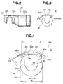
- the generally U-shaped base portion 32b of the piston 32 is formed at its axially rear end with a so-called turn stopper portion 82.
- the turn stopper portion 82 functions to suppress or at least minimize undesired turning movement of the piston 32 relative to the corresponding cylinder chamber 18.
- the turn stopper portion 82 comprises a major part 82a with a slightly rounded outer surface which faces radially outward. Laterally opposed sides (or shoulder parts) 82b and 82b of the major part 82a are smoothly rounded. If desired, the major part 82a may have a flat outer surface in place of the slightly rounded outer surface.
- the rounded outer surface defined by each shoulder part 82b has a radius of curvature of "r" (see Fig. 4). Preferably, the value "r" is equal to or greater than 1 mm.
- an inner cylindrical surface of the casing 12 is formed, at a portion facing the turn stopper portion 82 of the piston 32, with a concave recess 83 having a cylindrical surface 83a.
- a small given clearance "L 1 " is defined between each rounded shoulder part 82b of the turn stopper portion 82 of the piston 32 and the cylindrical surface 83a of the casing 12.
- the rounded left shoulder part 82b of the turn stopper portion 82 of the piston 32 stops or minimizes the turning of the piston 32 by abutting against the cylindrical surface 83a of the concave recess 83 of the casing 12. It is to be noted that due to the nature of the rounded surfaces respectively possessed by the rounded left shoulder part 82b and the cylindrical surface 83a, a so-called “surface-to-surface contact” is established therebetween upon such abutting.
- the rounded left shoulder part 82b leaves a wedge-shaped oil catching pocket between it and the cylindrical surface 83a, the splashed lubricant oil in the crank chamber 20 is permitted to smoothly penetrate between the turn stopper portion 82 and the cylindrical surface 83a from the pocket.
- L 2 is a distance between the left and right rounded shoulder parts 82b and 82b of the turn stopper portion 82.
- the distance “L 2 " is the distance which is defined between a center point of one contact area which is produced between the left rounded shoulder part 32b and the cylindrical surface 83a when the piston 32 is turned in the direction of the arrow "D" and a center point of the other contact area which is produced when the piston 32 is turned in the other direction.
- the distance “L 2 " is equal to or greater than 0.9 times the diameter "Dp" of the piston head portion 32a of the piston 32.
- reference “R 1” designates a radius of curvature of the major part 82a of the turn stopper portion 82.
- the value “R 1” is greater than a radius "R p " of curvature of the piston head portion 32a of the piston 32.
- Reference “R 2” designates a radius of curvature of the cylindrical surface 83a of the casing 12, which is greater than "R p " but smaller than “R 1 ".
- the cylindrical surface 83a is a part of an imaginary cylinder whose center axis extends in parallel with the axis of the drive shaft 26. However, if desired, the cylindrical surface 83a may be a part of an imaginary cylinder whose center axis is common to the axis of the drive shaft 26.
- the cylindrical surfaces 83a for the turn stopper portions 82 of all the pistons 32 constitute a common cylinder surface whose center axis is common to the axis of the drive shaft 26.
- crescent space 85 between the major part 82a of the turn stopper portion 82 of the piston 32 and the cylindrical surface 83a of the casing 12, as shown.
- the crescent space 85 can serve as an oil sump into which the lubricant oil splashed by the swash plate 34 penetrates during operation of the compressor 10A. Due to provision of the oil sump 85, lubrication between the turn stopper portion 82 and the cylindrical surface 83a of the casing 12 is effectively carried out. In fact, the splashed lubricant oil can enter the crescent space 85 from the back of the turn stopper portion 82.
- the axial length of the cylindrical surface 83a is so determined as not to interfere with the reciprocative movement of the piston 32.
- the electromagnetic clutch 30 When, under operation of the engine, the electromagnetic clutch 30 is turned ON, the drive shaft 26 is rotated and thus the swash plate 34 is rotated together with the drive shaft 26. If the swash plate 34 is kept inclined relative to the drive shaft 26, the swash plate 34 makes a so-called “spiral turns" about the axis of the drive shaft 26 and thus, the pistons 32 make reciprocative movements relative to the cylinder chambers 18. With this, induction, compression and discharge of a refrigerant are carried out by the compressor 10A in the above-mentioned manner.
- the swash plate 34 makes the spiral turns while pushing and pulling the pistons 32 one after another. That is, under such operation, the peripheral portion of the swash plate 34 slidably passes at a high speed between the two bearing shoes 36 and 38, generating a force by which each piston 32 is subjected to undesired turning movement in one direction about the axis thereof. If, as is understood from Fig. 4, the turning movement of the piston 32 in the direction of the arrow "D" increases to a given degree namely "L 1 ", the rounded left shoulder part 82b of the turn stopper portion 82 of the piston 32 makes a so-called surface-to-surface contact with the cylindrical surface 83a of the casing 12. Thus, the undesired turning movement of the piston 32 is smoothly stopped without generating a marked noise.
- the rounded left shoulder part 82b leaves a wedge-shaped oil catching pocket between it and the cylindrical surface 83a, the lubricant oil splashed by the swash plate 34 in the crank chamber 20 can penetrate easily between the turn stopper portion 82 and the cylindrical surface 83a from the pocket.
- the crescent space 85 defined between the turn stopper portion 82 and the cylindrical surface 83a serves as an oil sump.
- the compressor 10A can be produced at low cost.
- the piston 32 can have a light weight structure. Thus, a load applied to the piston 32 under operation of the compressor 10A is reduced.
- the casing 12 can be easily produced with a simple machining process.
- variable displacement swash plate type compressor of a second embodiment of the present invention which is generally designated by numeral 10B.
- each piston 132 comprises a piston head portion 132a which is slidably disposed in the corresponding cylinder chamber 18 and a generally U-shaped base portion 132b which is always out of the cylinder chamber 18.
- the U-shaped base portion 132b is operatively engaged with a peripheral portion of a swash plate 34 in the same manner as in the case of the above-mentioned first embodiment 10A.
- the generally U-shaped base portion 132b of the piston 132 is formed at its axially rear end with a turn stopper portion 182.
- the turn stopper portion 182 is formed with a rounded outer surface 182a which faces radially outwardly.
- the radius "R 3 " of curvature of the rounded outer surface 182a is greater than a radius "R p " of curvature of the piston head portion 132a of the piston 132.
- an inner cylindrical surface of the casing 12 is formed, at a portion facing the turn stopper portion 182 of the piston 132, with a grooved surface 183.
- the grooved surface 183 comprises two axially extending bank portions 183a and 183a and an axially extending groove 183b defined between the two bank portions 183a.
- the bank portions 183a and 183a have each a cylindrical top surface which is concentric with the axis of the drive shaft 26. That is, the cylindrical top surfaces of all of the bank portions 183a constitute a part of an imaginary cylinder whose axis is common to the axis of the drive shaft 26. Designated by reference “R 4 " in Fig. 8 is the radius of the imaginary cylinder. However, if desired, the cylindrical top surface of the paired bank portions 183a may be constructed to be eccentric from the axis of the drive shaft 26. As is seen from this drawing, upon assembly of the piston 132, a small given clearance "L 3 " is defined between the top of each bank portion 183a and the rounded outer surface 182a of the turn stopper portion 182.
- the rounded left part of the turn stopper portion 182 stops or minimizes the turning of the piston 132 by abutting against the left bank portion 183a.
- the groove 183b formed in the casing 12 can serve as an oil sump in which the lubricant oil is collected.
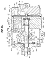
- variable displacement swash plate type compressor of a third embodiment of the present invention which is generally designated by numeral 10C.
- the compressor 10C comprises a cylinder block 12 and first and second heads 14 and 16 which are secured to axially opposed ends of the cylinder block 12. These three parts 12, 14 and 16 are constructed of an aluminum alloy. These three members are united tight by means of bolts (no numerals).
- the cylinder block 12 has a plurality of cylinder chambers 18 defined therein.
- the second head 16 has a crank chamber 20 defined therein.
- the first head 14 is connected to the cylinder block 12 through a valve sheet 22.
- the valve sheet 22 is provided with intake and discharge valves (not shown). These valves are circumferentially arranged at evenly spaced intervals on the valve sheet 22.
- Designated by numeral 24 is a valve body possessed by one of the discharge valves.
- a drive shaft 26 extends axially in the cylinder block 12 and the second head 16.
- the second head 16 has a bore 16a through which the drive shaft 26 extends to the outside.
- a radial bearing 40 is disposed in the bore 16a to bear the drive shaft 26, and an oil seal 40a is arranged near the bearing 40 for hermetically isolating the crank chamber 20.
- a pulley is connected to the drive shaft 26 through an electromagnetic clutch.
- a transmission belt (not shown) driven by an engine is put around the pulley.
- the cylinder chambers 18 are circumferentially formed in the cylinder block 12 at evenly spaced intervals.
- the cylinder chambers 18 are the same in construction and have respective pistons 232 slidably disposed therein.
- the pistons 232 are the same in construction.
- Each piston 232 is constructed of an aluminum alloy and comprises a piston head portion 232a which is slidably disposed in the corresponding cylinder chamber 18 and a generally U-shaped base portion 232b which is always out of the cylinder chamber 18.
- the piston head portion 232a is coated with a fluororesin film or the like to achieve a smoother movement thereof in the cylinder chamber 18.
- the U-shaped base portion 232b is engaged with a peripheral portion of a swash plate 34 through two semi-spherical bearing shoes 36 and 38.
- Opposed walls defined in a recess of the U-shaped base portion 232b of the piston 232 have spherical recesses (no numerals) into which spherical outer portions of the two bearing shoes 36 and 38 are slidably received, and opposed flat walls of the two bearing shoes 36 and 38 slidably put therebetween the peripheral flat portion of the swash plate 34.
- the swash plate 34 employed in this embodiment 10C essentially consists of a journal portion and an annular portion which are coupled through a screw connection.
- the journal portion is constructed of a cast iron, while, the annular portion is constructed of a steel.
- the swash plate 34 has a balancer 34a.
- a rotor member 42 is disposed on the drive shaft 26 to rotate therewith.
- a thrust bearing 42a Operatively disposed between the rotor member 42 and the second head 16 is a thrust bearing 42a.
- a spherical slider member 44 is axially slidably disposed on the drive shaft 26.
- the slider member 44 is formed with a spherical outer surface as shown.
- the swash plate 34 is pivotally disposed on the spherical outer surface of the slider member 44.
- the swash plate 34 is formed with a concave bore with which the spherical outer surface of the slider member 44 is slidably engaged.
- the swash plate 34 and the rotor member 42 are formed with respective links 46 and 48.
- a pin 50 extending from the link 46 of the swash plate 34 extends into an elongate slot 52 formed in the link 48 of the rotor member 42, so that the swash plate 34 and the rotor member 42 are hinged to each other.
- a pair of aligned pins 44a are arranged between the swash plate 34 and the slider member 44 to effect the pivotal movement of the swash plate 34 about the common axis of the aligned pins.
- Designated by numerals 26a and 26b are springs which are disposed about the drive shaft 26 to bias the slider member 44 in opposed directions.
- Designated by numerals 26c and 26d are radial and thrust bearings for bearing a right end portion of the drive shaft 26.
- the first head 14 has a known control valve "Cv" installed therein. Due to work of this control valve "Cv", the amount of refrigerant discharged from the compressor 10C can be adjusted, and the inlet pressure of the compressor 10C can be kept constant.
- Inlet and outlet ports 54 and 56 are formed in the first head 14, as shown.
- the inlet port 54 receives a return refrigerant from an evaporator (not shown).
- the refrigerant is then introduced into the cylinder chambers 18 in order through an intake opening 54a and the intake valves (not shown) of the valve sheet 22 in response to the intake stroke of the corresponding pistons 232.
- the refrigerant in the cylinder chambers 18 is led into the outlet port 56 in order through the discharge valves (not shown) of the valve sheet 22.
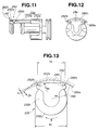
- the generally U-shaped base portion 232b of the piston 232 is formed at its axially rear end with a so-called turn stopper portion 282.
- the turn stopper portion 282 comprises a major part 282a with a slightly rounded outer surface which faces radially outward.
- laterally opposed sides 282b and 282b of the major part 282a are smoothly rounded with a radius of curvature of "r 1 " as is seen from Figs. 12 and 13, and, axially opposed sides 282c and 282c of the major part 282a are smoothly rounded with a radius of curvature of "r 2 ", as is seen from Figs. 11 and 14.
- the value "r 1 " and “r 2 " is each equal to or greater than 1 mm.
- an inner cylindrical surface of the casing 12 is formed, at a portion facing the turn stopper portion 282 of the piston 232, with a concave recess 283 having a cylindrical surface 283a.
- a small given clearance "L1" is defined between each rounded shoulder part 282b of the turn stopper portion 282 of the piston 232 and the cylindrical surface 283a of the casing 12.
- the rounded left shoulder part 282b of the turn stopper portion 282 stops or minimizes the turning of the piston 232 by abutting against the cylindrical surface 283a of the concave recess 283 of the casing 12. Due to the nature of the rounded surfaces respectively possessed by the rounded left shoulder part 282b and the cylindrical surface 283a, a so-called “surface-to-surface contact is established therebetween upon such abutting.
- This advantageous function is substantially the same as that of the above-mentioned first embodiment 10A.
- the third embodiment 10C has further the following advantageous function.
- L 2 is a distance between the left and right rounded shoulder parts 282b and 282b of the turn stopper portion 282.
- the distance “L 2 " is equal to or greater than 0.9 times the diameter "Dp" of the piston head portion 232a.
- Reference “R 1 " designates a radius of curvature of the slightly rounded major part 282a of the turn stopper portion 282.
- the value “R 1 " is greater than a radius “Rp” of curvature of the piston head portion 232a of the piston 232.
- Reference “R 2” designates a radius of curvature of the cylindrical surface 283a of the casing 12, which is greater than "R p " but smaller than “R 1 ".
- the cylindrical surface 283a is a part of an imaginary cylinder whose center axis extends in parallel with the axis of the drive shaft 26.
- the cylindrical surface 283a may be a part of an imaginary cylinder whose center axis is common to the axis of the drive shaft 26.
- the cylindrical surfaces 283a for the turn stopper portions 282 of all the pistons 232 constitute a common cylinder surface whose center axis is common to the axis of the drive shaft 26.
- the rounded left shoulder part 282b leaves a wedge-shaped oil catching pocket like in the case of the first embodiment 10A.
- the lubricant oil splashed by the swash plate 34 in the crank chamber 20 can penetrate easily between the turn stopper portion 282 and the cylindrical surface 283a from the pocket.
- the crescent space 285 defined between the turn stopper portion 282 and the cylindrical surface 283a serves as an oil sump.
- FIG. 15 there is shown a fourth embodiment 10D of the present invention, which is a modification of the above-mentioned third embodiment 10C.
- the major part 282a of the turn stopper portion 282 has a markedly rounded outer surface which has a radius of curvature of "R 4 ".
Landscapes
- Engineering & Computer Science (AREA)
- Manufacturing & Machinery (AREA)
- Mechanical Engineering (AREA)
- General Engineering & Computer Science (AREA)
- Compressors, Vaccum Pumps And Other Relevant Systems (AREA)
Applications Claiming Priority (12)
| Application Number | Priority Date | Filing Date | Title |
|---|---|---|---|
| JP8836395 | 1995-04-13 | ||
| JP08836295A JP3285730B2 (ja) | 1995-04-13 | 1995-04-13 | 斜板式コンプレッサ |
| JP8836295 | 1995-04-13 | ||
| JP8836395 | 1995-04-13 | ||
| JP88363/95 | 1995-04-13 | ||
| JP88362/95 | 1995-04-13 | ||
| JP10871995 | 1995-05-02 | ||
| JP10871995A JP3320587B2 (ja) | 1995-04-13 | 1995-05-02 | 斜板式コンプレッサ |
| JP108719/95 | 1995-05-02 | ||
| JP33923195 | 1995-12-26 | ||
| JP339231/95 | 1995-12-26 | ||
| JP33923195A JP3285747B2 (ja) | 1995-12-26 | 1995-12-26 | 斜板式コンプレッサ |
Publications (3)
| Publication Number | Publication Date |
|---|---|
| EP0740076A2 true EP0740076A2 (fr) | 1996-10-30 |
| EP0740076A3 EP0740076A3 (fr) | 1996-12-11 |
| EP0740076B1 EP0740076B1 (fr) | 2000-07-05 |
Family
ID=27467500
Family Applications (1)
| Application Number | Title | Priority Date | Filing Date |
|---|---|---|---|
| EP96105801A Expired - Lifetime EP0740076B1 (fr) | 1995-04-13 | 1996-04-12 | Compresseur à plateau en biais à compression variable |
Country Status (3)
| Country | Link |
|---|---|
| US (1) | US5706716A (fr) |
| EP (1) | EP0740076B1 (fr) |
| DE (1) | DE69609118T2 (fr) |
Cited By (17)
| Publication number | Priority date | Publication date | Assignee | Title |
|---|---|---|---|---|
| EP0799994A1 (fr) * | 1996-04-03 | 1997-10-08 | Sanden Corporation | Compresseur à plateau en biais à structure de calage de la rotation du piston améliorée |
| EP0819849A2 (fr) * | 1996-07-15 | 1998-01-21 | Kabushiki Kaisha Toyoda Jidoshokki Seisakusho | Piston pour compresseurs à piston |
| EP0819850A2 (fr) * | 1996-07-15 | 1998-01-21 | Kabushiki Kaisha Toyoda Jidoshokki Seisakusho | Piston pour compresseurs à piston |
| EP0844390A1 (fr) | 1996-11-21 | 1998-05-27 | Sanden Corporation | Compresseur à plateau en biais comportant un plateau en matériel très résistant à l'usure |
| EP0844389A1 (fr) * | 1996-11-25 | 1998-05-27 | Sanden Corporation | Mécanisme à piston pour appareil de déplacement de fluide |
| EP0844391A2 (fr) * | 1996-11-25 | 1998-05-27 | General Motors Corporation | Pièce anti-rotation pour les pistons d'un compresseur de climatisation pour véhicule automobile |
| EP0952340A2 (fr) * | 1998-04-17 | 1999-10-27 | Kabushiki Kaisha Toyoda Jidoshokki Seisakusho | Piston pour un compresseur à plateau en biais pour réfrigérant |
| EP1085207A2 (fr) * | 1999-09-14 | 2001-03-21 | Kabushiki Kaisha Toyoda Jidoshokki Seisakusho | Compresseur avec structure d'attenuation de pulsations |
| EP1092872A2 (fr) * | 1999-10-12 | 2001-04-18 | Kabushiki Kaisha Toyoda Jidoshokki Seisakusho | Piston pour compresseur à plateau en biais |
| EP1167758A1 (fr) * | 2000-06-27 | 2002-01-02 | Halla Climate Control Corp. | Structure empêchant la rotation d'un piston pour un compresseur à plateau en biais à capacité variable |
| EP1158164A3 (fr) * | 2000-05-24 | 2002-07-10 | Kabushiki Kaisha Toyota Jidoshokki | Piston pour compresseur à plateau en biais |
| EP1087136A3 (fr) * | 1999-09-24 | 2002-07-10 | Kabushiki Kaisha Toyota Jidoshokki | Tête de piston de compresseur à plateau en biais avec chanfrein |
| EP1291522A1 (fr) * | 2000-06-07 | 2003-03-12 | Zexel Valeo Climate Control Corporation | Compresseur a cylindree variable de type a plateau oscillant |
| EP1329634A1 (fr) | 2002-01-17 | 2003-07-23 | Zexel Valeo Climate Control Corporation | Compresseur à plateau en biais ou à plateau oscillant |
| US6672199B2 (en) | 2000-10-17 | 2004-01-06 | Otfried Schwarzkopf | Cylinder block of an axial piston compressor with elongated cylinder face |
| DE10053944B4 (de) * | 2000-10-31 | 2006-06-22 | Zexel Valeo Compressor Europe Gmbh | Zylinderblock eines Axialkolbenverdichters und Kolben für einen Axialkolbenverdichter |
| WO2013082379A1 (fr) * | 2011-12-01 | 2013-06-06 | Caterpillar Inc. | Ensemble piston pour dispositif de translation de fluide |
Families Citing this family (14)
| Publication number | Priority date | Publication date | Assignee | Title |
|---|---|---|---|---|
| US6368073B1 (en) * | 1997-05-26 | 2002-04-09 | Zexel Corporation | Swash plate compressor |
| JP3880158B2 (ja) | 1997-10-21 | 2007-02-14 | カルソニックカンセイ株式会社 | 斜板式圧縮機 |
| JPH11125177A (ja) | 1997-10-21 | 1999-05-11 | Calsonic Corp | 斜板式可変容量圧縮機 |
| JPH11125176A (ja) * | 1997-10-21 | 1999-05-11 | Calsonic Corp | 斜板式可変容量圧縮機 |
| JP3880159B2 (ja) | 1997-10-21 | 2007-02-14 | カルソニックカンセイ株式会社 | 斜板式可変容量圧縮機 |
| JP3860311B2 (ja) * | 1997-10-21 | 2006-12-20 | カルソニックカンセイ株式会社 | 斜板式圧縮機 |
| JP3880160B2 (ja) * | 1997-10-21 | 2007-02-14 | カルソニックカンセイ株式会社 | 斜板式可変容量圧縮機 |
| JP2000356185A (ja) * | 1999-06-15 | 2000-12-26 | Toyota Autom Loom Works Ltd | 斜板式圧縮機用ピストン |
| US6325599B1 (en) | 2000-04-04 | 2001-12-04 | Visteon Global Technologies, Inc. | Piston having anti-rotation for swashplate compressor |
| EP1167760B1 (fr) * | 2000-06-19 | 2008-10-15 | Kabushiki Kaisha Toyota Jidoshokki | Compresseur à plateau en biais |
| JP2004190507A (ja) * | 2002-12-09 | 2004-07-08 | Sanden Corp | 斜板式圧縮機 |
| DE102006001173A1 (de) * | 2006-01-08 | 2007-07-12 | Obrist Engineering Gmbh | Hubkolbenkompressor mit einer Kolbenführung |
| US7455009B2 (en) * | 2006-06-09 | 2008-11-25 | Visteon Global Technologies, Inc. | Hinge for a variable displacement compressor |
| CN102192120B (zh) * | 2010-03-12 | 2013-05-01 | 北京华德液压工业集团有限责任公司 | 限位弧型滑轨摆盘直轴柱塞泵 |
Citations (3)
| Publication number | Priority date | Publication date | Assignee | Title |
|---|---|---|---|---|
| DE4327948A1 (de) * | 1992-08-21 | 1994-03-03 | Toyoda Automatic Loom Works | Führungsmechanismus für einen sich hin und her bewegenden Kolben eines Kolbenkompressors |
| EP0587023A1 (fr) * | 1992-09-02 | 1994-03-16 | Sanden Corporation | Compresseur à piston à déplacement variable |
| JPH06346844A (ja) * | 1993-06-04 | 1994-12-20 | Toyota Autom Loom Works Ltd | 斜板式圧縮機におけるピストン回動規制構造 |
Family Cites Families (10)
| Publication number | Priority date | Publication date | Assignee | Title |
|---|---|---|---|---|
| US1714145A (en) * | 1922-11-14 | 1929-05-21 | Sperry Dev Co | Crankless engine |
| DK132669C (da) * | 1973-07-05 | 1976-07-12 | M R G Teisen | Aksialstempelmotor eller -pumpe |
| DE2357338A1 (de) * | 1973-08-15 | 1975-02-27 | Gunnar Olaf Vesterga Rasmussen | Kraftuebertragungsvorrichtung fuer kolbenmotoren oder -pumpen |
| JPS5823030Y2 (ja) * | 1978-12-30 | 1983-05-17 | 株式会社豊田自動織機製作所 | 斜板式圧縮機 |
| JPH0128311Y2 (fr) * | 1980-11-27 | 1989-08-29 | ||
| JPS60175783A (ja) * | 1984-02-21 | 1985-09-09 | Sanden Corp | 容量可変型斜板式圧縮機 |
| JPH01227877A (ja) * | 1988-03-04 | 1989-09-12 | Toyota Autom Loom Works Ltd | 斜板式圧縮機 |
| JPH01227876A (ja) * | 1988-03-04 | 1989-09-12 | Toyota Autom Loom Works Ltd | 斜板式圧縮機 |
| JP2572690Y2 (ja) * | 1992-09-02 | 1998-05-25 | サンデン株式会社 | 斜板式圧縮機のピストン回転防止機構 |
| JPH08109874A (ja) * | 1994-10-11 | 1996-04-30 | Calsonic Corp | 斜板式コンプレッサ |
-
1996
- 1996-04-12 DE DE69609118T patent/DE69609118T2/de not_active Expired - Lifetime
- 1996-04-12 US US08/631,078 patent/US5706716A/en not_active Expired - Lifetime
- 1996-04-12 EP EP96105801A patent/EP0740076B1/fr not_active Expired - Lifetime
Patent Citations (3)
| Publication number | Priority date | Publication date | Assignee | Title |
|---|---|---|---|---|
| DE4327948A1 (de) * | 1992-08-21 | 1994-03-03 | Toyoda Automatic Loom Works | Führungsmechanismus für einen sich hin und her bewegenden Kolben eines Kolbenkompressors |
| EP0587023A1 (fr) * | 1992-09-02 | 1994-03-16 | Sanden Corporation | Compresseur à piston à déplacement variable |
| JPH06346844A (ja) * | 1993-06-04 | 1994-12-20 | Toyota Autom Loom Works Ltd | 斜板式圧縮機におけるピストン回動規制構造 |
Non-Patent Citations (1)
| Title |
|---|
| PATENT ABSTRACTS OF JAPAN vol. 940, no. 12 & JP 06 346844 A (TOYOTA AUTOM LOOM WORKS LTD), 20 December 1994, * |
Cited By (30)
| Publication number | Priority date | Publication date | Assignee | Title |
|---|---|---|---|---|
| US5934172A (en) * | 1996-04-03 | 1999-08-10 | Sanden Corporation | Swash plate type compressor having an improved piston rotation regulating-structure |
| EP0799994A1 (fr) * | 1996-04-03 | 1997-10-08 | Sanden Corporation | Compresseur à plateau en biais à structure de calage de la rotation du piston améliorée |
| EP0819849A2 (fr) * | 1996-07-15 | 1998-01-21 | Kabushiki Kaisha Toyoda Jidoshokki Seisakusho | Piston pour compresseurs à piston |
| EP0819850A2 (fr) * | 1996-07-15 | 1998-01-21 | Kabushiki Kaisha Toyoda Jidoshokki Seisakusho | Piston pour compresseurs à piston |
| EP0819850A3 (fr) * | 1996-07-15 | 2000-11-15 | Kabushiki Kaisha Toyoda Jidoshokki Seisakusho | Piston pour compresseurs à piston |
| EP0819849A3 (fr) * | 1996-07-15 | 2000-11-08 | Kabushiki Kaisha Toyoda Jidoshokki Seisakusho | Piston pour compresseurs à piston |
| US5974946A (en) * | 1996-11-21 | 1999-11-02 | Sanden Corporation | Swash plate type compressor using swash plate made of highly wear-resistant material |
| EP0844390A1 (fr) | 1996-11-21 | 1998-05-27 | Sanden Corporation | Compresseur à plateau en biais comportant un plateau en matériel très résistant à l'usure |
| US5934170A (en) * | 1996-11-25 | 1999-08-10 | Sanden Corporation | Piston mechanism of fluid displacement apparatus |
| EP0844391A3 (fr) * | 1996-11-25 | 2000-10-25 | General Motors Corporation | Pièce anti-rotation pour les pistons d'un compresseur de climatisation pour véhicule automobile |
| EP0844391A2 (fr) * | 1996-11-25 | 1998-05-27 | General Motors Corporation | Pièce anti-rotation pour les pistons d'un compresseur de climatisation pour véhicule automobile |
| EP0844389A1 (fr) * | 1996-11-25 | 1998-05-27 | Sanden Corporation | Mécanisme à piston pour appareil de déplacement de fluide |
| EP0952340A2 (fr) * | 1998-04-17 | 1999-10-27 | Kabushiki Kaisha Toyoda Jidoshokki Seisakusho | Piston pour un compresseur à plateau en biais pour réfrigérant |
| US6422129B1 (en) | 1998-04-17 | 2002-07-23 | Kabushiki Kaisha Toyoda Jidoshokki Seisakusho | Swash plate type refrigerant compressor |
| EP0952340A3 (fr) * | 1998-04-17 | 2000-07-05 | Kabushiki Kaisha Toyoda Jidoshokki Seisakusho | Piston pour un compresseur à plateau en biais pour réfrigérant |
| EP1085207A2 (fr) * | 1999-09-14 | 2001-03-21 | Kabushiki Kaisha Toyoda Jidoshokki Seisakusho | Compresseur avec structure d'attenuation de pulsations |
| EP1085207A3 (fr) * | 1999-09-14 | 2002-01-23 | Kabushiki Kaisha Toyota Jidoshokki | Compresseur avec structure d'attenuation de pulsations |
| EP1087136A3 (fr) * | 1999-09-24 | 2002-07-10 | Kabushiki Kaisha Toyota Jidoshokki | Tête de piston de compresseur à plateau en biais avec chanfrein |
| EP1092872A2 (fr) * | 1999-10-12 | 2001-04-18 | Kabushiki Kaisha Toyoda Jidoshokki Seisakusho | Piston pour compresseur à plateau en biais |
| EP1092872B1 (fr) * | 1999-10-12 | 2006-12-20 | Kabushiki Kaisha Toyota Jidoshokki | Piston pour compresseur à plateau en biais |
| US6532860B2 (en) | 2000-05-24 | 2003-03-18 | Kabushiki Kaisha Toyoda Jidoshokki Seisakusho | Piston type compressor and inner mold for making the same |
| EP1158164A3 (fr) * | 2000-05-24 | 2002-07-10 | Kabushiki Kaisha Toyota Jidoshokki | Piston pour compresseur à plateau en biais |
| EP1291522A1 (fr) * | 2000-06-07 | 2003-03-12 | Zexel Valeo Climate Control Corporation | Compresseur a cylindree variable de type a plateau oscillant |
| EP1291522A4 (fr) * | 2000-06-07 | 2003-10-15 | Zexel Valeo Climate Contr Corp | Compresseur a cylindree variable de type a plateau oscillant |
| EP1167758A1 (fr) * | 2000-06-27 | 2002-01-02 | Halla Climate Control Corp. | Structure empêchant la rotation d'un piston pour un compresseur à plateau en biais à capacité variable |
| US6672199B2 (en) | 2000-10-17 | 2004-01-06 | Otfried Schwarzkopf | Cylinder block of an axial piston compressor with elongated cylinder face |
| DE10051420B4 (de) * | 2000-10-17 | 2009-03-05 | Valeo Compressor Europe Gmbh | Zylinderblock eines Axialkolbenverdichters mit verlängerter Zylinderlauffläche |
| DE10053944B4 (de) * | 2000-10-31 | 2006-06-22 | Zexel Valeo Compressor Europe Gmbh | Zylinderblock eines Axialkolbenverdichters und Kolben für einen Axialkolbenverdichter |
| EP1329634A1 (fr) | 2002-01-17 | 2003-07-23 | Zexel Valeo Climate Control Corporation | Compresseur à plateau en biais ou à plateau oscillant |
| WO2013082379A1 (fr) * | 2011-12-01 | 2013-06-06 | Caterpillar Inc. | Ensemble piston pour dispositif de translation de fluide |
Also Published As
| Publication number | Publication date |
|---|---|
| EP0740076B1 (fr) | 2000-07-05 |
| US5706716A (en) | 1998-01-13 |
| DE69609118D1 (de) | 2000-08-10 |
| DE69609118T2 (de) | 2000-11-16 |
| EP0740076A3 (fr) | 1996-12-11 |
Similar Documents
| Publication | Publication Date | Title |
|---|---|---|
| US5706716A (en) | Variable displacement swash plate type compressor | |
| US5173032A (en) | Non-clutch compressor | |
| EP0780572B1 (fr) | Compresseur à plateau en biais | |
| JP2555026B2 (ja) | 容量可変型圧縮機 | |
| US5765464A (en) | Reciprocating pistons of piston-type compressor | |
| US6139282A (en) | Variable capacity refrigerant compressor with an aluminum cam plate means | |
| EP0809024B1 (fr) | Piston alternatif de compresseur à piston | |
| US5953980A (en) | Piston type compressors | |
| EP1394411B1 (fr) | Compresseur à déplacement variable du type à disque oblique | |
| KR100300818B1 (ko) | 가변용량형경사판식압축기 | |
| EP1512870A1 (fr) | Compresseur à plateau en biais et à déplacement variable | |
| EP1092872A2 (fr) | Piston pour compresseur à plateau en biais | |
| JP4506031B2 (ja) | 可変容量式圧縮機 | |
| JPH09242667A (ja) | 往復動型圧縮機 | |
| US6224349B1 (en) | Reciprocating type compressor having orbiting valve plate | |
| US20010029837A1 (en) | Hinge mechanism for variable displacement compressor | |
| US20030002991A1 (en) | Compressor | |
| JPH08109874A (ja) | 斜板式コンプレッサ | |
| US6293761B1 (en) | Variable displacement swash plate type compressor having pivot pin | |
| KR100210216B1 (ko) | 가변 변위형 회전 사판식 압축기 | |
| JP2755193B2 (ja) | 圧縮機におけるピストン | |
| US6705204B2 (en) | Swash plate-type | |
| JPS58176484A (ja) | 往復式圧縮機 | |
| JP3320587B2 (ja) | 斜板式コンプレッサ | |
| US20010042438A1 (en) | Piston for swash plate type compressor |
Legal Events
| Date | Code | Title | Description |
|---|---|---|---|
| PUAI | Public reference made under article 153(3) epc to a published international application that has entered the european phase |
Free format text: ORIGINAL CODE: 0009012 |
|
| PUAL | Search report despatched |
Free format text: ORIGINAL CODE: 0009013 |
|
| 17P | Request for examination filed |
Effective date: 19960412 |
|
| AK | Designated contracting states |
Kind code of ref document: A2 Designated state(s): DE FR GB IT SE |
|
| AK | Designated contracting states |
Kind code of ref document: A3 Designated state(s): DE FR GB IT SE |
|
| 17Q | First examination report despatched |
Effective date: 19980409 |
|
| GRAG | Despatch of communication of intention to grant |
Free format text: ORIGINAL CODE: EPIDOS AGRA |
|
| GRAG | Despatch of communication of intention to grant |
Free format text: ORIGINAL CODE: EPIDOS AGRA |
|
| GRAH | Despatch of communication of intention to grant a patent |
Free format text: ORIGINAL CODE: EPIDOS IGRA |
|
| GRAH | Despatch of communication of intention to grant a patent |
Free format text: ORIGINAL CODE: EPIDOS IGRA |
|
| GRAA | (expected) grant |
Free format text: ORIGINAL CODE: 0009210 |
|
| AK | Designated contracting states |
Kind code of ref document: B1 Designated state(s): DE FR GB IT SE |
|
| REF | Corresponds to: |
Ref document number: 69609118 Country of ref document: DE Date of ref document: 20000810 |
|
| ITF | It: translation for a ep patent filed | ||
| ET | Fr: translation filed | ||
| PLBE | No opposition filed within time limit |
Free format text: ORIGINAL CODE: 0009261 |
|
| STAA | Information on the status of an ep patent application or granted ep patent |
Free format text: STATUS: NO OPPOSITION FILED WITHIN TIME LIMIT |
|
| 26N | No opposition filed | ||
| REG | Reference to a national code |
Ref country code: GB Ref legal event code: IF02 |
|
| PGFP | Annual fee paid to national office [announced via postgrant information from national office to epo] |
Ref country code: SE Payment date: 20050419 Year of fee payment: 10 |
|
| PG25 | Lapsed in a contracting state [announced via postgrant information from national office to epo] |
Ref country code: SE Free format text: LAPSE BECAUSE OF NON-PAYMENT OF DUE FEES Effective date: 20060413 |
|
| PGFP | Annual fee paid to national office [announced via postgrant information from national office to epo] |
Ref country code: IT Payment date: 20060430 Year of fee payment: 11 |
|
| EUG | Se: european patent has lapsed | ||
| PG25 | Lapsed in a contracting state [announced via postgrant information from national office to epo] |
Ref country code: IT Free format text: LAPSE BECAUSE OF NON-PAYMENT OF DUE FEES Effective date: 20070412 |
|
| REG | Reference to a national code |
Ref country code: GB Ref legal event code: 746 Effective date: 20090924 |
|
| REG | Reference to a national code |
Ref country code: FR Ref legal event code: PLFP Year of fee payment: 20 |
|
| PGFP | Annual fee paid to national office [announced via postgrant information from national office to epo] |
Ref country code: DE Payment date: 20150408 Year of fee payment: 20 Ref country code: GB Payment date: 20150408 Year of fee payment: 20 |
|
| PGFP | Annual fee paid to national office [announced via postgrant information from national office to epo] |
Ref country code: FR Payment date: 20150408 Year of fee payment: 20 |
|
| REG | Reference to a national code |
Ref country code: DE Ref legal event code: R071 Ref document number: 69609118 Country of ref document: DE |
|
| REG | Reference to a national code |
Ref country code: GB Ref legal event code: PE20 Expiry date: 20160411 |
|
| PG25 | Lapsed in a contracting state [announced via postgrant information from national office to epo] |
Ref country code: GB Free format text: LAPSE BECAUSE OF EXPIRATION OF PROTECTION Effective date: 20160411 |