EP0952340A2 - Piston pour un compresseur à plateau en biais pour réfrigérant - Google Patents
Piston pour un compresseur à plateau en biais pour réfrigérant Download PDFInfo
- Publication number
- EP0952340A2 EP0952340A2 EP99106300A EP99106300A EP0952340A2 EP 0952340 A2 EP0952340 A2 EP 0952340A2 EP 99106300 A EP99106300 A EP 99106300A EP 99106300 A EP99106300 A EP 99106300A EP 0952340 A2 EP0952340 A2 EP 0952340A2
- Authority
- EP
- European Patent Office
- Prior art keywords
- piston
- oil groove
- swash plate
- peripheral surface
- compressor according
- Prior art date
- Legal status (The legal status is an assumption and is not a legal conclusion. Google has not performed a legal analysis and makes no representation as to the accuracy of the status listed.)
- Withdrawn
Links
- 239000003507 refrigerant Substances 0.000 title claims abstract description 39
- 230000002093 peripheral effect Effects 0.000 claims abstract description 56
- 230000006835 compression Effects 0.000 claims abstract description 24
- 238000007906 compression Methods 0.000 claims abstract description 24
- 229910000838 Al alloy Inorganic materials 0.000 claims abstract description 5
- XEEYBQQBJWHFJM-UHFFFAOYSA-N Iron Chemical compound [Fe] XEEYBQQBJWHFJM-UHFFFAOYSA-N 0.000 claims abstract description 4
- 239000000463 material Substances 0.000 claims abstract description 3
- 239000003921 oil Substances 0.000 claims description 51
- 230000000694 effects Effects 0.000 claims description 5
- 229910000676 Si alloy Inorganic materials 0.000 claims description 4
- CSDREXVUYHZDNP-UHFFFAOYSA-N alumanylidynesilicon Chemical compound [Al].[Si] CSDREXVUYHZDNP-UHFFFAOYSA-N 0.000 claims description 4
- 230000004044 response Effects 0.000 claims description 3
- 239000010953 base metal Substances 0.000 claims description 2
- 238000006243 chemical reaction Methods 0.000 description 17
- 239000000314 lubricant Substances 0.000 description 12
- CURLTUGMZLYLDI-UHFFFAOYSA-N Carbon dioxide Chemical compound O=C=O CURLTUGMZLYLDI-UHFFFAOYSA-N 0.000 description 10
- 229910002092 carbon dioxide Inorganic materials 0.000 description 9
- 230000007246 mechanism Effects 0.000 description 5
- 238000000034 method Methods 0.000 description 5
- 230000008859 change Effects 0.000 description 4
- 229910052751 metal Inorganic materials 0.000 description 4
- 239000002184 metal Substances 0.000 description 4
- 230000008569 process Effects 0.000 description 4
- 238000005461 lubrication Methods 0.000 description 3
- 150000002739 metals Chemical class 0.000 description 3
- 238000001816 cooling Methods 0.000 description 2
- 230000005496 eutectics Effects 0.000 description 2
- 238000005057 refrigeration Methods 0.000 description 2
- 230000001105 regulatory effect Effects 0.000 description 2
- 239000004215 Carbon black (E152) Substances 0.000 description 1
- 241001311413 Pison Species 0.000 description 1
- 238000004378 air conditioning Methods 0.000 description 1
- 238000013459 approach Methods 0.000 description 1
- 239000001569 carbon dioxide Substances 0.000 description 1
- 230000001419 dependent effect Effects 0.000 description 1
- 238000006073 displacement reaction Methods 0.000 description 1
- 230000007613 environmental effect Effects 0.000 description 1
- 239000012530 fluid Substances 0.000 description 1
- 229930195733 hydrocarbon Natural products 0.000 description 1
- 150000002430 hydrocarbons Chemical class 0.000 description 1
- 235000015250 liver sausages Nutrition 0.000 description 1
- -1 polytetrafluoroethylene Polymers 0.000 description 1
- 229920001343 polytetrafluoroethylene Polymers 0.000 description 1
- 239000004810 polytetrafluoroethylene Substances 0.000 description 1
- 238000007789 sealing Methods 0.000 description 1
Images


Classifications
-
- F—MECHANICAL ENGINEERING; LIGHTING; HEATING; WEAPONS; BLASTING
- F04—POSITIVE - DISPLACEMENT MACHINES FOR LIQUIDS; PUMPS FOR LIQUIDS OR ELASTIC FLUIDS
- F04B—POSITIVE-DISPLACEMENT MACHINES FOR LIQUIDS; PUMPS
- F04B27/00—Multi-cylinder pumps specially adapted for elastic fluids and characterised by number or arrangement of cylinders
- F04B27/08—Multi-cylinder pumps specially adapted for elastic fluids and characterised by number or arrangement of cylinders having cylinders coaxial with, or parallel or inclined to, main shaft axis
- F04B27/10—Multi-cylinder pumps specially adapted for elastic fluids and characterised by number or arrangement of cylinders having cylinders coaxial with, or parallel or inclined to, main shaft axis having stationary cylinders
- F04B27/1036—Component parts, details, e.g. sealings, lubrication
- F04B27/109—Lubrication
-
- F—MECHANICAL ENGINEERING; LIGHTING; HEATING; WEAPONS; BLASTING
- F04—POSITIVE - DISPLACEMENT MACHINES FOR LIQUIDS; PUMPS FOR LIQUIDS OR ELASTIC FLUIDS
- F04B—POSITIVE-DISPLACEMENT MACHINES FOR LIQUIDS; PUMPS
- F04B27/00—Multi-cylinder pumps specially adapted for elastic fluids and characterised by number or arrangement of cylinders
- F04B27/08—Multi-cylinder pumps specially adapted for elastic fluids and characterised by number or arrangement of cylinders having cylinders coaxial with, or parallel or inclined to, main shaft axis
- F04B27/0873—Component parts, e.g. sealings; Manufacturing or assembly thereof
- F04B27/0878—Pistons
-
- F—MECHANICAL ENGINEERING; LIGHTING; HEATING; WEAPONS; BLASTING
- F05—INDEXING SCHEMES RELATING TO ENGINES OR PUMPS IN VARIOUS SUBCLASSES OF CLASSES F01-F04
- F05C—INDEXING SCHEME RELATING TO MATERIALS, MATERIAL PROPERTIES OR MATERIAL CHARACTERISTICS FOR MACHINES, ENGINES OR PUMPS OTHER THAN NON-POSITIVE-DISPLACEMENT MACHINES OR ENGINES
- F05C2201/00—Metals
- F05C2201/02—Light metals
- F05C2201/021—Aluminium
-
- F—MECHANICAL ENGINEERING; LIGHTING; HEATING; WEAPONS; BLASTING
- F05—INDEXING SCHEMES RELATING TO ENGINES OR PUMPS IN VARIOUS SUBCLASSES OF CLASSES F01-F04
- F05C—INDEXING SCHEME RELATING TO MATERIALS, MATERIAL PROPERTIES OR MATERIAL CHARACTERISTICS FOR MACHINES, ENGINES OR PUMPS OTHER THAN NON-POSITIVE-DISPLACEMENT MACHINES OR ENGINES
- F05C2225/00—Synthetic polymers, e.g. plastics; Rubber
- F05C2225/04—PTFE [PolyTetraFluorEthylene]
Definitions
- the present invention relates to a swash plate type refrigerant compressor using CO 2 as a refrigerant. More particularly, the present invention relates to a swash plate type piston-operated refrigerant compressor incorporating therein pistons reciprocating to compress the refrigerant and having an improved sliding performance and an extended operating life.
- a single-headed piston operated swash plate type compressor used for a vehicle climate control system includes a swash plate or a cam plate mounted on the drive shaft in a crank chamber, so that the rotation of the swash plate cooperating with the drive shaft is converted into the linear motion of the pistons inserted in cylinder bores.
- the refrigerant gas returning from an external refrigeration system is sucked into the cylinder bores from a suction chamber and, after being compressed, is discharged into a discharge chamber.
- many single-headed swash plate type compressors are so configured that the refrigerant returned gas is introduced directly into the cylinder bores without passing through the crank chamber as described above.
- the lubrication of the sliding portions and elements arranged in the crank chamber therefore, are primarily dependent on the lubricant supplied to the crank chamber together with the blow-by gas.
- the amount of the blow-by gas depends on the size of the fitting gap between the cylinder bores and the pistons.
- the fitting gap is required to have an appreciable size. In such a case, the problem of reduced compression efficiency is posed.
- the compression reaction force and the inertia force of the pistons act on the swash plate, and the force thus acting on the swash plate is exerted on the pistons as a reaction force.
- the swash plate is inclined with respect to a plane perpendicular to the center axis of the drive shaft, part of the force acting on the pistons is exerted in such a direction as to press the pistons against the inner periphery of the cylinder bores.
- the respective pistons receive side forces from the inner peripheral surface of the corresponding cylinder bores.
- the side force is so great that the pistons unavoidably come into direct contact with the cylinder bores even if piston rings are fitted on the pistons.
- an object of the present invention is to provide a swash plate type piston-operated refrigerant compressor using the CO 2 refrigerant in which the blow-by gas amount is limited in cooperation with the piston ring mounted on the pistons while at the same time preventing direct contact between the cylinder bores and the pistons made of metals of the same type.
- Another object of the invention is to provide a swash plate type refrigerant compressor in which superior lubrication of the piston sliding portion is secured and a sufficient amount of lubricant can be supplied to the sliding elements and portions including the swash plate, the shoes, the hinge mechanism and the bearings in the crank chamber.
- a swash plate type refrigerant compressor which comprises:
- the blow-by gas amount is determined by the width of the closed gap of the piston ring and the fitting gap between the cylinder bores and the pistons. Since the fluororesin film is formed on the outer peripheral surface of the pistons, however, direct contact is surely avoided between the metals, of the same type, of the cylinder bores and the pistons. Thus, the fitting gap is minimized so that the blow-by gas amount, i.e. the leakage amount of the compressed refrigerant is reduced to prevent the reduced performance of the compressor. At the same time, the surface contact through the fluororesin film can sufficiently resist a large side force.
- the casing having the cylinder bores is formed of a hypereutectic aluminum-silicon alloy and the piston ring is made of an iron metal.
- the lubricant passage area can be increased for a lower viscous resistance without increasing the gas flow rate. Therefore, the lubricant can be held in the fitting boundary with the cylinder bores.
- the second oil groove is formed in such a position as to be partly exposed to the interior of the crank chamber at least when the pistons reach the bottom dead center. Even when the refrigerant compressor is of variable displacement type with an extremely small angle of inclination of the swash plate, the lubricant is positively supplied into the crank chamber from the second oil groove, and therefore superior lubrication is achieved. Furthermore, in the case where the second oil groove is formed on the outer peripheral surface of the pistons where the effect of the side force can be avoided as far as possible, the second oil groove is not strongly pressed against the cylinder bores. Therefore, the wear and damage to both the pistons and the cylinder bores can be prevented.
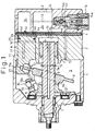
- a front housing 1 is coupled to the front end surface of a cylinder block 2.
- a rear housing 3 is coupled to the rear end surface of the cylinder block 2 through a valve plate 4.
- the front housing 1, the cylinder block 2 and the rear housing 3 constitute members of a compressor casing.
- a suction chamber 3a and a discharge chamber 3b are formed between the rear housing 3 and the valve plate 4.
- the refrigerant gas (CO 2 ) from an external refrigeration circuit (not shown) is introduced directly into the suction chamber 3a through an inlet port 3c.
- the valve plate 4 includes suction ports 4a, a suction valve 4b, a discharge port 4c and a discharge valve 4d.
- a crank chamber 5 is formed between the front housing 1 and the cylinder block 2.
- a drive shaft 6 is rotatably supported on the front housing 1 and the cylinder block 2 through a pair of bearings 7 and arranged through the crank chamber 5.
- a support hole 2b is formed at the central portion of the cylinder block 2. The rear end of the drive shaft 6 is inserted into the support hole 2b, and the rear end thereof is supported on the inner peripheral surface of the support hole 2b through the bearings 7.
- a lug plate 8 is fixed on the drive shaft 6.
- a swash plate 9 is supported on the drive shaft 6 slidably and movably in the direction along the axis L thereof in the crank chamber 5.
- the swash plate 9 is coupled to the lug plate 8 through a hinge mechanism 10.
- the hinge mechanism 10 includes a support arm 19 formed on the lug plate 8 and a pair of guide pins 20 formed on the swash plate 9.
- the guide pins 20 are slidably inserted into a pair of guide holes 19a, respectively, formed in the support arm 19.
- the hinge mechanism 10 is adapted to rotate the swash plate 9 integrally with the drive shaft 6. Further, the hinge mechanism 10 guides the swash plate 9 to move in the direction along the axis L and to be inclined.
- a plurality of cylinder bores 2a are formed in the cylinder block 2 around the drive shaft 6 and extend in the direction along the axis L.
- a single-headed piston 11 is housed in the cylinder bores 2a.
- the tail of the piston 11 is formed with a groove 11a.
- the hemispherical portions of a pair of shoes 12 are fitted relatively movably within the opposed inner wall surfaces of, the groove 11a.
- the swash plate 9 is held slidably between the flat portions of the shoes 12. The rotational motion of the swash plate 9 is converted into the reciprocal linear motion of the piston 11 through the shoes 12, so that the piston 11 longitudinally reciprocates in the cylinder bores 2a.
- a suction stroke when the piston 11 moves from its top dead center toward its bottom dead center, the refrigerant gas in the suction chamber 3a pushes a suction valve 4b from a suction port 4a to open the latter and flows into the cylinder bores 2a.
- a compression stroke when the piston 11 moves from the bottom dead center to the top dead center, on the other hand, the refrigerant gas in the cylinder bores 2a is compressed, pushes a discharge valve 4d from a discharge port 4c to open the port 4c and is discharged into a discharge chamber 3b.
- a thrust bearing 21 is arranged between the lug plate 8 and the inner surface of the front housing 1. With the compression of the refrigerant gas, the compression reaction force is exerted on the piston 11. This compression reaction force is received by the front housing 1 through the piston 11, the swash plate 9, the lug plate 8 and the thrust bearing 21.
- the piston 11 is formed integrally with a stopper 22.
- the stopper 22 has a peripheral surface of substantially the same diameter as the inner peripheral surface of the front housing 1.
- the peripheral surface of the stopper 22 is in contact with the inner peripheral surface of the front housing 1 in order to prevent the rotation of the piston 11 about the center axis S.
- the compressor has a gas supply passage 13 fluidly connecting the discharge chamber 3b and the crank chamber 5. Specifically, an end of the gas supply passage 13 is open to the crank chamber 5, and the other end thereof is connected to an electromagnetic valve 14 mounted on the rear housing 3.
- the gas supply passage 13 extends from the electromagnetic valve 14 to the discharge chamber 3b.
- the electromagnetic valve 14 is arranged midway in the gas supply passage 13.
- the electromagnetic valve or solenoid valve 14 has a solenoid 14a. Upon energization of the solenoid 14a, a valve body 14b closes a valve hole 14c. When the solenoid 14a is deenergized, on the other hand, the valve body 14b opens the valve hole 14c.
- a gas withdrawal passage 6a is formed in the drive shaft 6.
- the gas withdrawal passage 6a has an inlet open to the crank chamber 5, forward of the drive shaft 6a, and an outlet open into the support hole 2b, rearward of the drive shaft 6a.
- a gas withdrawal hole 2c is connected to the interior of the support hole 2b and the suction chamber 3a.
- the refrigerant gas in the crank chamber 5 only flows out into the suction chamber 3a through the gas supply passage 6a and the gas withdrawal hole 2c, so that the internal pressure of the crank chamber 5 approaches the low internal pressure of the suction chamber 3a.
- the difference is reduced between the internal pressure of the crank chamber 5 and the internal pressure of the cylinder bores 2a, and as shown in Fig. 1, the inclination angle of the swash plate 9 (the angle of inclination from a plane perpendicular to the axis of rotational of the drive shaft 6) becomes maximum, thereby maximizing the discharge capacity of the compressor.
- the swash plate 9 has a stop protrusion 9a formed on the front side thereof, which is brought into contact with the lug plate 8 and thus the swash plate is restricted to not exceed a predetermined maximum inclination angle.
- the swash plate 9 is also restricted to a minimum inclination angle by being brought into contact with a ring 15 mounted on the rear portion of the drive shaft 6.
- the intermediate portion of the gas supply passage 13 is closed and opened in response to the energization and deenergization of the solenoid 14a of the solenoid valve 14.
- the internal pressure of the crank chamber 5 is regulated.
- the difference also changes between the internal pressure of the crank chamber 5 exerted on the front surface (the left side in Fig. 1) of the piston 11 and the internal pressure of the cylinder bores 2a exerted on the rear surface (the right side subjected to compression in Fig. 1) of the piston 11.
- the inclination angle of the swash plate 9 coupled to the piston 11 through the shoes 12 also undergoes a change.
- the change in the angle of inclination of the swash plate 9 causes a change in the stroke amount of the piston 11 to thereby regulate the discharge capacity of the compressor.
- the solenoid 14a of the electromagnetic valve 14 is energized or deenergized selectively in accordance with the information such as the cooling load under the control of a controller (not shown). In other words, the discharge capacity of the compressor is regulated in accordance with the cooling load.
- the cylinder block 2 having the cylinder bores 2a and the piston 11 are fabricated of an aluminum alloy, or preferably a hyper eutectic aluminum-silicon alloy.
- an annular groove 25a is formed, into which the piston ring 25 is fitted.
- a fluororesin (polytetrafluoroethylene) film is formed on the outer peripheral surface of the piston 11 for avoiding direct contact with a metal of the same type and minimizing the fitting gap K with the cylinder bores 2a.
- each piston 11 is formed with a later-described oil groove for holding the lubricant against the corresponding cylinder bores 2a and assuring a positive oil supply into the crank chamber 5.
- a first oil groove 16 is formed extending along the peripheral direction in parallel to and in the area below the annular groove 25a formed in the outer peripheral surface of the piston 11.
- the first oil groove 16 is formed in annular fashion around the whole periphery of the piston 11. The first oil groove 16 is not exposed into the crank chamber 5 from inside the cylinder bores 2a when the piston 11 moves to the bottom dead center thereof.
- the piston 11 is further formed with a second oil groove 17.
- the second oil groove 17 is formed extending from the area further below the first oil groove 16 along the center axis S of the piston 11.
- the second oil groove 17 is provided and configured as described hereinbelow.
- the second oil groove 17 is formed in the range E of the 9 o'clock position to the 10:30 position on the peripheral surface of the piston 11. Further, the second oil groove 17 is formed at such a position and with such a length as not to be exposed to the interior of the crank chamber 5 when the piston 11 moves to the vicinity of the top dead center.
- part of the refrigerant gas that has passed through the closed gap of the piston ring 25 leaks into the crank chamber 5 as a blow-by gas through the limited fitting gap K between the outer peripheral surface of the piston 11 and the inner peripheral surface of the cylinder bores 2a.
- the lubricant that has entered the fitting gap K together with the blow-by gas is trapped and stored in the first oil groove 16 with the movement of the piston 11.
- the internal pressure of the oil groove 16 increases due to the blow-by gas in the fitting gap K.
- the second oil groove 17, however, is exposed at least partially in the crank chamber 5 in other than the case where the piston 11 moves to the vicinity of the top dead center.
- the internal pressure of the second oil groove 17, therefore, is equal to or only slightly higher than the internal pressure of the crank chamber 5.
- the differential pressure between the oil grooves 16, 17 in spaced opposed relation to each other through the fitting gap K causes the lubricant in the first oil groove 16 to flow into the second oil groove 17.
- the viscous resistance of the oil component high in viscosity is affected by the length.
- the length is reduced by forming the second oil groove 17, while at the same time enlarging the area of the lubricant passage in the long seal portion thereby to attenuate the viscous resistance.
- the lubricant in the second oil groove 17 is supplied, through the groove portion exposed in the crank chamber 5, to the sliding portions in the crank chamber 5, i.e. the relative sliding portions of the swash plate 9, the shoes 2 and the piston 11, thereby to lubricate those portions sufficiently.
- the reaction force (hereinafter referred to as the side force) is exerted on the piston 11, while in reciprocal motion, from the inner peripheral surface of the cylinder bores 2a due to the compression reaction force and its own inertia.
- the second oil groove 17 is preferably formed at a position on the peripheral surface of the piston 11 as free of the effect of the side force as possible.
- the component force f 2 causes the tail of the piston 11 to tilt toward the component force f 2 .
- the peripheral surface of the tail of the piston 11 is pressed against the inner peripheral surface in the vicinity of the opening of the cylinder bores 2a with a force corresponding to the component force f 2 .
- the peripheral surface of the tail of the piston 11 is subjected to a large reaction force (side force) Fa corresponding to the component force f 2 from the inner peripheral surface in the vicinity of the opening of the cylinder bores 2a.
- the position at which the side force Fa acts on the piston 11 changes with the reciprocal motion of the piston 11.
- the compressed refrigerant gas staying in the cylinder bores 2a is expanded again with the movement of the piston 11 from top dead center to bottom dead center.
- the refrigerant gas starts to be sucked into the cylinder bores 2a.
- the compression reaction force is not exerted on the swash plate 9, and the force F 0 acting on the swash plate 9 is substantially equal to the force of inertia of the piston 11.
- the piston 11 is subjected to the reaction force Fs mainly based on the force of inertia from the swash plate 9.
- This reaction force Fs can be decomposed into a component force f 1 along the direction of movement of the piston 11 and a component force f 2 substantially along the rotational direction R of the swash plate 9, in accordance with the inclination angle of the swash plate 9.
- the component force f 2 causes the tail of the pison 11 to tilt in the direction of the component force f 2 .
- the piston 11 is subjected to the side force Fa corresponding to the component force f 2 from the inner peripheral surface in the vicinity of the opening of the cylinder bores 2a.
- the force F 0 acting on the swash plate 9 becomes substantially zero. Therefore, the side force Fa is not substantially exerted on the piston 11.
- Fig. 4A is a graph showing the relation between the rotational angle of the swash plate 9 (the coverage of the piston 11) and the magnitude of the side force Fa acting on the piston 11.
- the rotational angle of the swash pate 9 when the piston 11 is at top dead center is assumed to be 0°.
- the side force Fa may assume a negative value. This indicates that the direction of each force described above becomes reversed.
- the graph of Fig. 4A indicates that when the rotational angle of the swash plate 9 is 0°, i.e. when the piston 11 is at top dead center, the side force Fa acting on the piston 11 becomes a maximum.
- the position on the peripheral surface of the piston 11 where the maximum side force Fa is exerted is the 6 o'clock position as shown in Fig. 4B.
- the range E1 of 3 o'clock to 9 o'clock positions with the 6 o'clock position at the center thereof is where the piston 11 is pressed, strongly against the inner peripheral surface of the cylinder bore 2a.
- the opening edge of the second oil groove 17 is strongly pressed against the inner peripheral surface of the cylinder bores 2a, thereby sometimes wearing or damaging the piston 11 or the cylinder bores 2a.
- the second oil groove 17 is formed in the range other than the range E1 of 3 o'clock to 9 o'clock positions, i.e. in the range E2 of 9 o'clock to 3 o'clock positions on the peripheral surface of the piston 11.
- the second oil groove 17 is preferably formed in the part of the range E2 of 9 o'clock to 3 o'clock where the side force Fa exerted on the peripheral surface of the piston 11 is minimum.
- the graph of Fig. 4A indicates that the side force Fa acting on the piston 11 is smaller when the piston 11 is in suction stroke (when the rotational angle of the swash plate 9 is 0° to 180°) than when the piston 11 in compression stroke (when the rotational angle of the swash plate 9 is 180° to 360°).
- the side force Fa exerted in the range of 9 o'clock to 12 o'clock is smaller than that exerted in the range of 12 o'clock to 3 o'clock.
- the second oil groove 17 is preferably not formed in the neighborhood of the 12 o'clock position on the peripheral surface of the piston 11.
- the second oil groove 17 is formed in the range E of 9 o'clock to 10:30 on the peripheral surface of the piston 11.
- the peripheral wall of the cylinder bores and the piston are fabricated of an aluminum alloy, direct contact between metals of the same type is avoided by the fluororesin film formed on the outer peripheral surface of the piston, and the fitting gap with the cylinder bores is minimized.
- the amount of the blow-by gas can be limited to minimum.
- the CO 2 gas can be employed as a refrigerant gas without reducing the compression performance.
- the viscous resistance of the oil component can be reduced to secure a smooth sliding motion of the piston without increasing the gas flow rate through the fitting gap with the cylinder bores. Further, a sufficient amount of oil can be supplied to the sliding portions in the crank chamber through these oil grooves.
- the second oil groove is formed in a phase minimizing the effect of the side force on the outer peripheral surface of the piston, the second oil groove can be sufficiently protected from wear and damage and the side force can be positively supported by the fluororesin film.
Applications Claiming Priority (2)
| Application Number | Priority Date | Filing Date | Title |
|---|---|---|---|
| JP10107532A JPH11294322A (ja) | 1998-04-17 | 1998-04-17 | 斜板式圧縮機 |
| JP10753298 | 1998-04-17 |
Publications (2)
| Publication Number | Publication Date |
|---|---|
| EP0952340A2 true EP0952340A2 (fr) | 1999-10-27 |
| EP0952340A3 EP0952340A3 (fr) | 2000-07-05 |
Family
ID=14461586
Family Applications (1)
| Application Number | Title | Priority Date | Filing Date |
|---|---|---|---|
| EP99106300A Withdrawn EP0952340A3 (fr) | 1998-04-17 | 1999-04-16 | Piston pour un compresseur à plateau en biais pour réfrigérant |
Country Status (3)
| Country | Link |
|---|---|
| US (1) | US6422129B1 (fr) |
| EP (1) | EP0952340A3 (fr) |
| JP (1) | JPH11294322A (fr) |
Cited By (2)
| Publication number | Priority date | Publication date | Assignee | Title |
|---|---|---|---|---|
| EP1236896A2 (fr) * | 2001-03-02 | 2002-09-04 | Kabushiki Kaisha Toyota Jidoshokki | Piston de compresseur |
| EP1264987A1 (fr) * | 2000-03-07 | 2002-12-11 | Zexel Valeo Climate Control Corporation | Compresseur du type a cylindree variable |
Families Citing this family (14)
| Publication number | Priority date | Publication date | Assignee | Title |
|---|---|---|---|---|
| JP2001165049A (ja) * | 1999-12-08 | 2001-06-19 | Toyota Autom Loom Works Ltd | 往復式圧縮機 |
| EP1164289A3 (fr) * | 2000-06-13 | 2003-09-24 | Kabushiki Kaisha Toyota Jidoshokki | Compresseur à plateau en biais |
| JP2003129954A (ja) * | 2001-10-19 | 2003-05-08 | Toyota Industries Corp | 流体機械用ピストンおよび流体機械 |
| JP2004190507A (ja) * | 2002-12-09 | 2004-07-08 | Sanden Corp | 斜板式圧縮機 |
| US20060171824A1 (en) * | 2005-01-28 | 2006-08-03 | Carrier Corporation | Compressor connecting rod bearing design |
| JP4801409B2 (ja) * | 2005-10-06 | 2011-10-26 | 三菱重工業株式会社 | 低温流体用昇圧ポンプ |
| US7849783B2 (en) * | 2006-05-31 | 2010-12-14 | Ggb, Inc. | Plastic shoes for compressors |
| KR100917449B1 (ko) * | 2007-06-01 | 2009-09-14 | 한라공조주식회사 | 압축기 |
| DE102007049389A1 (de) * | 2007-10-15 | 2009-04-16 | Linde Material Handling Gmbh | Axialkolbenmaschine in Schrägscheibenbauweise |
| DE202007017659U1 (de) * | 2007-12-18 | 2008-04-17 | Sauer-Danfoss Gmbh & Co Ohg | Hydrostatische Verdrängereinheit |
| JP5164710B2 (ja) * | 2008-07-23 | 2013-03-21 | サンデン株式会社 | ピストン式圧縮機 |
| JP5282670B2 (ja) * | 2009-06-12 | 2013-09-04 | 株式会社リコー | ピストン、エアポンプ、エア吐出装置及び画像形成装置 |
| CN104121186A (zh) * | 2014-06-24 | 2014-10-29 | 济南大学 | 液压柱塞泵自润滑装置 |
| US10544752B2 (en) * | 2017-07-14 | 2020-01-28 | Hyundai Motor Company | Aluminum foam core piston with coaxial laser bonded aerogel/ceramic head |
Citations (5)
| Publication number | Priority date | Publication date | Assignee | Title |
|---|---|---|---|---|
| US4351227A (en) * | 1980-05-20 | 1982-09-28 | General Motors Corporation | Multicylinder swash plate compressor piston ring arrangement |
| US4519119A (en) * | 1980-11-19 | 1985-05-28 | Kabushiki Kaisha Toyoda Jidoshokki Seisakusho | Method of manufacturing a piston for a swash plate type compressor |
| EP0740076A2 (fr) * | 1995-04-13 | 1996-10-30 | Calsonic Corporation | Compresseur à plateau en biais à compression variable |
| EP0818625A2 (fr) * | 1996-07-08 | 1998-01-14 | Kabushiki Kaisha Toyoda Jidoshokki Seisakusho | Piston de compresseur et procédé servant à enduire le piston |
| EP0844389A1 (fr) * | 1996-11-25 | 1998-05-27 | Sanden Corporation | Mécanisme à piston pour appareil de déplacement de fluide |
Family Cites Families (7)
| Publication number | Priority date | Publication date | Assignee | Title |
|---|---|---|---|---|
| JPS5535339A (en) | 1978-09-01 | 1980-03-12 | Ricoh Co Ltd | Developing system |
| JPH07174071A (ja) * | 1993-08-10 | 1995-07-11 | Sanden Corp | 圧縮機の吐出機構 |
| JPH08326655A (ja) * | 1995-06-05 | 1996-12-10 | Calsonic Corp | 斜板式コンプレッサ |
| US5921756A (en) * | 1995-12-04 | 1999-07-13 | Denso Corporation | Swash plate compressor including double-headed pistons having piston sections with different cross-sectional areas |
| JPH10281059A (ja) * | 1997-04-02 | 1998-10-20 | Sanden Corp | プーリー直結型容量可変型斜板式圧縮機 |
| JP3790942B2 (ja) * | 1997-05-26 | 2006-06-28 | 株式会社ヴァレオサーマルシステムズ | 斜板式圧縮機 |
| JP3851971B2 (ja) * | 1998-02-24 | 2006-11-29 | 株式会社デンソー | Co2用圧縮機 |
-
1998
- 1998-04-17 JP JP10107532A patent/JPH11294322A/ja active Pending
-
1999
- 1999-04-13 US US09/291,419 patent/US6422129B1/en not_active Expired - Fee Related
- 1999-04-16 EP EP99106300A patent/EP0952340A3/fr not_active Withdrawn
Patent Citations (5)
| Publication number | Priority date | Publication date | Assignee | Title |
|---|---|---|---|---|
| US4351227A (en) * | 1980-05-20 | 1982-09-28 | General Motors Corporation | Multicylinder swash plate compressor piston ring arrangement |
| US4519119A (en) * | 1980-11-19 | 1985-05-28 | Kabushiki Kaisha Toyoda Jidoshokki Seisakusho | Method of manufacturing a piston for a swash plate type compressor |
| EP0740076A2 (fr) * | 1995-04-13 | 1996-10-30 | Calsonic Corporation | Compresseur à plateau en biais à compression variable |
| EP0818625A2 (fr) * | 1996-07-08 | 1998-01-14 | Kabushiki Kaisha Toyoda Jidoshokki Seisakusho | Piston de compresseur et procédé servant à enduire le piston |
| EP0844389A1 (fr) * | 1996-11-25 | 1998-05-27 | Sanden Corporation | Mécanisme à piston pour appareil de déplacement de fluide |
Cited By (5)
| Publication number | Priority date | Publication date | Assignee | Title |
|---|---|---|---|---|
| EP1264987A1 (fr) * | 2000-03-07 | 2002-12-11 | Zexel Valeo Climate Control Corporation | Compresseur du type a cylindree variable |
| EP1264987A4 (fr) * | 2000-03-07 | 2004-07-28 | Zexel Valeo Climate Contr Corp | Compresseur du type a cylindree variable |
| EP1236896A2 (fr) * | 2001-03-02 | 2002-09-04 | Kabushiki Kaisha Toyota Jidoshokki | Piston de compresseur |
| EP1236896A3 (fr) * | 2001-03-02 | 2003-07-16 | Kabushiki Kaisha Toyota Jidoshokki | Piston de compresseur |
| US6705207B2 (en) | 2001-03-02 | 2004-03-16 | Kabushiki Kaisha Toyota Jidoshokki | Piston type compressor |
Also Published As
| Publication number | Publication date |
|---|---|
| US6422129B1 (en) | 2002-07-23 |
| EP0952340A3 (fr) | 2000-07-05 |
| JPH11294322A (ja) | 1999-10-26 |
Similar Documents
| Publication | Publication Date | Title |
|---|---|---|
| US6422129B1 (en) | Swash plate type refrigerant compressor | |
| KR100274497B1 (ko) | 압축기 | |
| US5816134A (en) | Compressor piston and piston type compressor | |
| KR100268317B1 (ko) | 압축기의 축 밀봉구조 | |
| US20020127116A1 (en) | Axial piston compressor | |
| US5562425A (en) | Gas suction structure in piston type compressor | |
| US5988041A (en) | Piston for compressors | |
| EP1211444A2 (fr) | Joint d'étanchéité d'arbre de type à lèvre et éléments de guidage ayant un tel joint | |
| KR970001763B1 (ko) | 용량가변형 압축기 | |
| KR101645276B1 (ko) | 용량 가변형 사판식 압축기 | |
| EP0881386B2 (fr) | Compresseur à plateau en biais | |
| EP0844389B1 (fr) | Compresseur à plateau en biais | |
| CA2221475C (fr) | Compresseur a cylindree variable | |
| EP1811177A2 (fr) | Structure pour récupération d'huile dans un compresseur | |
| US5842406A (en) | Piston for compressors including a restrictor to prevent the piston from rotating | |
| JPH09242667A (ja) | 往復動型圧縮機 | |
| KR100733518B1 (ko) | 회전 사판 수용 조립체 | |
| EP1092872A2 (fr) | Piston pour compresseur à plateau en biais | |
| EP1055817A2 (fr) | Tête de piston d'un compresseur à plateau en biais avec surface de réduction de frottement | |
| JP2006336562A (ja) | 等速ジョイント及びそれを用いた揺動斜板型圧縮機 | |
| US6332394B1 (en) | Piston for swash plate type compressor, wherein head portion includes radially inner sliding projection connected to neck portion | |
| EP1087136B1 (fr) | Tête de piston de compresseur à plateau en biais avec chanfrein | |
| EP1039128A2 (fr) | Compresseur à plateau en biais | |
| JP3666170B2 (ja) | 斜板型圧縮機 | |
| EP1092873A2 (fr) | Alésages dans le cylindre d'un compresseur à plateau en biais |
Legal Events
| Date | Code | Title | Description |
|---|---|---|---|
| PUAI | Public reference made under article 153(3) epc to a published international application that has entered the european phase |
Free format text: ORIGINAL CODE: 0009012 |
|
| 17P | Request for examination filed |
Effective date: 19990416 |
|
| AK | Designated contracting states |
Kind code of ref document: A2 Designated state(s): DE FR IT |
|
| AX | Request for extension of the european patent |
Free format text: AL;LT;LV;MK;RO;SI |
|
| PUAL | Search report despatched |
Free format text: ORIGINAL CODE: 0009013 |
|
| AK | Designated contracting states |
Kind code of ref document: A3 Designated state(s): AT BE CH CY DE DK ES FI FR GB GR IE IT LI LU MC NL PT SE |
|
| AX | Request for extension of the european patent |
Free format text: AL;LT;LV;MK;RO;SI |
|
| AKX | Designation fees paid |
Free format text: DE FR IT |
|
| RAP1 | Party data changed (applicant data changed or rights of an application transferred) |
Owner name: KABUSHIKI KAISHA TOYOTA JIDOSHOKKI |
|
| 17Q | First examination report despatched |
Effective date: 20041119 |
|
| STAA | Information on the status of an ep patent application or granted ep patent |
Free format text: STATUS: THE APPLICATION IS DEEMED TO BE WITHDRAWN |
|
| 18D | Application deemed to be withdrawn |
Effective date: 20060419 |