EP0737510B1 - Überzogene Teilchen zur Herstellung von Diamanten und Verfahren zur Herstellung von Diamantschleifkörpern zum Sägen - Google Patents
Überzogene Teilchen zur Herstellung von Diamanten und Verfahren zur Herstellung von Diamantschleifkörpern zum Sägen Download PDFInfo
- Publication number
- EP0737510B1 EP0737510B1 EP96105789A EP96105789A EP0737510B1 EP 0737510 B1 EP0737510 B1 EP 0737510B1 EP 96105789 A EP96105789 A EP 96105789A EP 96105789 A EP96105789 A EP 96105789A EP 0737510 B1 EP0737510 B1 EP 0737510B1
- Authority
- EP
- European Patent Office
- Prior art keywords
- diamond
- particles
- coated
- powder
- compact
- Prior art date
- Legal status (The legal status is an assumption and is not a legal conclusion. Google has not performed a legal analysis and makes no representation as to the accuracy of the status listed.)
- Expired - Lifetime
Links
- 239000002245 particle Substances 0.000 title claims description 163
- 239000010432 diamond Substances 0.000 title claims description 129
- 229910003460 diamond Inorganic materials 0.000 title claims description 122
- 238000000034 method Methods 0.000 title claims description 88
- 230000002194 synthesizing effect Effects 0.000 title claims description 27
- 230000008569 process Effects 0.000 title claims description 15
- 238000004519 manufacturing process Methods 0.000 title description 3
- 239000000843 powder Substances 0.000 claims description 57
- 239000000463 material Substances 0.000 claims description 53
- 229910052751 metal Inorganic materials 0.000 claims description 52
- 239000002184 metal Substances 0.000 claims description 52
- 239000002904 solvent Substances 0.000 claims description 49
- 239000011248 coating agent Substances 0.000 claims description 20
- 238000000576 coating method Methods 0.000 claims description 20
- 229910002804 graphite Inorganic materials 0.000 claims description 20
- 239000010439 graphite Substances 0.000 claims description 20
- 238000010438 heat treatment Methods 0.000 claims description 20
- 238000005056 compaction Methods 0.000 claims description 19
- 229920006243 acrylic copolymer Polymers 0.000 claims description 17
- 238000005507 spraying Methods 0.000 claims description 9
- 239000003575 carbonaceous material Substances 0.000 claims description 6
- 238000002844 melting Methods 0.000 claims description 4
- 230000008018 melting Effects 0.000 claims description 4
- 238000003825 pressing Methods 0.000 claims description 2
- 238000009694 cold isostatic pressing Methods 0.000 claims 1
- 239000013078 crystal Substances 0.000 description 79
- OKTJSMMVPCPJKN-UHFFFAOYSA-N Carbon Chemical compound [C] OKTJSMMVPCPJKN-UHFFFAOYSA-N 0.000 description 62
- 239000000203 mixture Substances 0.000 description 39
- 229910052799 carbon Inorganic materials 0.000 description 33
- KFZMGEQAYNKOFK-UHFFFAOYSA-N Isopropanol Chemical compound CC(C)O KFZMGEQAYNKOFK-UHFFFAOYSA-N 0.000 description 22
- 239000010410 layer Substances 0.000 description 20
- 230000007423 decrease Effects 0.000 description 17
- 239000011148 porous material Substances 0.000 description 16
- 239000002002 slurry Substances 0.000 description 15
- LFQSCWFLJHTTHZ-UHFFFAOYSA-N Ethanol Chemical compound CCO LFQSCWFLJHTTHZ-UHFFFAOYSA-N 0.000 description 11
- 239000000956 alloy Substances 0.000 description 11
- 229910045601 alloy Inorganic materials 0.000 description 11
- 229960004592 isopropanol Drugs 0.000 description 11
- 239000003960 organic solvent Substances 0.000 description 11
- 229910001030 Iron–nickel alloy Inorganic materials 0.000 description 10
- UFHFLCQGNIYNRP-UHFFFAOYSA-N Hydrogen Chemical compound [H][H] UFHFLCQGNIYNRP-UHFFFAOYSA-N 0.000 description 9
- 239000001257 hydrogen Substances 0.000 description 9
- 229910052739 hydrogen Inorganic materials 0.000 description 9
- 239000002356 single layer Substances 0.000 description 9
- 239000007789 gas Substances 0.000 description 8
- 229910000831 Steel Inorganic materials 0.000 description 7
- 239000007771 core particle Substances 0.000 description 7
- 239000010959 steel Substances 0.000 description 7
- 239000002994 raw material Substances 0.000 description 6
- IJGRMHOSHXDMSA-UHFFFAOYSA-N Atomic nitrogen Chemical compound N#N IJGRMHOSHXDMSA-UHFFFAOYSA-N 0.000 description 5
- 239000002775 capsule Substances 0.000 description 5
- 230000000052 comparative effect Effects 0.000 description 5
- 235000019441 ethanol Nutrition 0.000 description 5
- 239000000314 lubricant Substances 0.000 description 5
- 230000008901 benefit Effects 0.000 description 4
- -1 maleic anhydride ester Chemical class 0.000 description 4
- 239000002202 Polyethylene glycol Substances 0.000 description 3
- 238000001035 drying Methods 0.000 description 3
- 238000002474 experimental method Methods 0.000 description 3
- 229920001223 polyethylene glycol Polymers 0.000 description 3
- XKRFYHLGVUSROY-UHFFFAOYSA-N Argon Chemical compound [Ar] XKRFYHLGVUSROY-UHFFFAOYSA-N 0.000 description 2
- 239000001856 Ethyl cellulose Substances 0.000 description 2
- ZZSNKZQZMQGXPY-UHFFFAOYSA-N Ethyl cellulose Chemical compound CCOCC1OC(OC)C(OCC)C(OCC)C1OC1C(O)C(O)C(OC)C(CO)O1 ZZSNKZQZMQGXPY-UHFFFAOYSA-N 0.000 description 2
- 230000001464 adherent effect Effects 0.000 description 2
- 239000000853 adhesive Substances 0.000 description 2
- 230000001070 adhesive effect Effects 0.000 description 2
- 239000010426 asphalt Substances 0.000 description 2
- 238000006243 chemical reaction Methods 0.000 description 2
- 238000005229 chemical vapour deposition Methods 0.000 description 2
- 229910052804 chromium Inorganic materials 0.000 description 2
- 239000004567 concrete Substances 0.000 description 2
- 229920001249 ethyl cellulose Polymers 0.000 description 2
- 235000019325 ethyl cellulose Nutrition 0.000 description 2
- 229910052742 iron Inorganic materials 0.000 description 2
- 238000005551 mechanical alloying Methods 0.000 description 2
- 150000002739 metals Chemical class 0.000 description 2
- 239000011812 mixed powder Substances 0.000 description 2
- 238000000465 moulding Methods 0.000 description 2
- 229910052759 nickel Inorganic materials 0.000 description 2
- 229910052757 nitrogen Inorganic materials 0.000 description 2
- 239000011368 organic material Substances 0.000 description 2
- 238000007747 plating Methods 0.000 description 2
- 238000004904 shortening Methods 0.000 description 2
- 239000004575 stone Substances 0.000 description 2
- 229910000990 Ni alloy Inorganic materials 0.000 description 1
- 150000001298 alcohols Chemical class 0.000 description 1
- 229910052786 argon Inorganic materials 0.000 description 1
- 230000008859 change Effects 0.000 description 1
- 230000006835 compression Effects 0.000 description 1
- 238000007906 compression Methods 0.000 description 1
- 238000007796 conventional method Methods 0.000 description 1
- 238000005520 cutting process Methods 0.000 description 1
- 229910001873 dinitrogen Inorganic materials 0.000 description 1
- 239000006185 dispersion Substances 0.000 description 1
- 238000007772 electroless plating Methods 0.000 description 1
- 239000000945 filler Substances 0.000 description 1
- 235000013305 food Nutrition 0.000 description 1
- 230000006872 improvement Effects 0.000 description 1
- 239000012535 impurity Substances 0.000 description 1
- 239000011261 inert gas Substances 0.000 description 1
- 239000007788 liquid Substances 0.000 description 1
- 239000007791 liquid phase Substances 0.000 description 1
- 229910052748 manganese Inorganic materials 0.000 description 1
- 238000010068 moulding (rubber) Methods 0.000 description 1
- 230000003647 oxidation Effects 0.000 description 1
- 238000007254 oxidation reaction Methods 0.000 description 1
- 239000004014 plasticizer Substances 0.000 description 1
- 238000007873 sieving Methods 0.000 description 1
- 239000007787 solid Substances 0.000 description 1
- 239000011343 solid material Substances 0.000 description 1
- 238000003756 stirring Methods 0.000 description 1
- 230000009466 transformation Effects 0.000 description 1
Images



Classifications
-
- B—PERFORMING OPERATIONS; TRANSPORTING
- B01—PHYSICAL OR CHEMICAL PROCESSES OR APPARATUS IN GENERAL
- B01J—CHEMICAL OR PHYSICAL PROCESSES, e.g. CATALYSIS OR COLLOID CHEMISTRY; THEIR RELEVANT APPARATUS
- B01J3/00—Processes of utilising sub-atmospheric or super-atmospheric pressure to effect chemical or physical change of matter; Apparatus therefor
- B01J3/06—Processes using ultra-high pressure, e.g. for the formation of diamonds; Apparatus therefor, e.g. moulds or dies
- B01J3/062—Processes using ultra-high pressure, e.g. for the formation of diamonds; Apparatus therefor, e.g. moulds or dies characterised by the composition of the materials to be processed
-
- B—PERFORMING OPERATIONS; TRANSPORTING
- B01—PHYSICAL OR CHEMICAL PROCESSES OR APPARATUS IN GENERAL
- B01J—CHEMICAL OR PHYSICAL PROCESSES, e.g. CATALYSIS OR COLLOID CHEMISTRY; THEIR RELEVANT APPARATUS
- B01J2203/00—Processes utilising sub- or super atmospheric pressure
- B01J2203/06—High pressure synthesis
- B01J2203/0605—Composition of the material to be processed
- B01J2203/061—Graphite
-
- B—PERFORMING OPERATIONS; TRANSPORTING
- B01—PHYSICAL OR CHEMICAL PROCESSES OR APPARATUS IN GENERAL
- B01J—CHEMICAL OR PHYSICAL PROCESSES, e.g. CATALYSIS OR COLLOID CHEMISTRY; THEIR RELEVANT APPARATUS
- B01J2203/00—Processes utilising sub- or super atmospheric pressure
- B01J2203/06—High pressure synthesis
- B01J2203/0605—Composition of the material to be processed
- B01J2203/062—Diamond
-
- B—PERFORMING OPERATIONS; TRANSPORTING
- B01—PHYSICAL OR CHEMICAL PROCESSES OR APPARATUS IN GENERAL
- B01J—CHEMICAL OR PHYSICAL PROCESSES, e.g. CATALYSIS OR COLLOID CHEMISTRY; THEIR RELEVANT APPARATUS
- B01J2203/00—Processes utilising sub- or super atmospheric pressure
- B01J2203/06—High pressure synthesis
- B01J2203/065—Composition of the material produced
- B01J2203/0655—Diamond
-
- B—PERFORMING OPERATIONS; TRANSPORTING
- B01—PHYSICAL OR CHEMICAL PROCESSES OR APPARATUS IN GENERAL
- B01J—CHEMICAL OR PHYSICAL PROCESSES, e.g. CATALYSIS OR COLLOID CHEMISTRY; THEIR RELEVANT APPARATUS
- B01J2203/00—Processes utilising sub- or super atmospheric pressure
- B01J2203/06—High pressure synthesis
- B01J2203/0675—Structural or physico-chemical features of the materials processed
- B01J2203/068—Crystal growth
Definitions
- the present invention relates to a process for synthesizing single crystal diamond particles having 20 ⁇ 60 U.S. mesh (hereafter mesh means U.S. mesh).
- the diamond particles are used as an abrasive for sawing, especially to cut stone, concrete and asphalt.
- the diamond particle which is used as an abrasive for sawing to cut the above materials is required to be high-strength and not friable. There is a strong mutual relationship between cutting performance (tool life) and particle strength. And it is well known that the particle strength depends on the perfection and symmetry of the diamond particle shape.
- Fig. 11 A When there is a lack portion 29 (broken or not grown portion) at the surface of a diamond particle 28 as shown in Fig. 11 A, strength of the particle decreases depending on the extent of the lack portion.
- Fig. 11 B shows a long and narrow diamond particle 30 and a sharp-edged diamond particle 30.
- Such diamond particles have low strength due to lack of symmetry.
- a high-strength diamond particle is required to have no or minimal lack portion and good symmetry.
- the environment of a growing diamond cause a lack portion or poor symmetry of a grown diamond.
- the growing diamonds contact each other or are unnaturally restricted, even though not contacting, by supply of raw material and the surroundings. For these reasons, many synthesized diamond particles have a lack portion and bad symmetry. Therefore, it is necessary to have sufficient distance between growing diamonds for synthesizing high-strength diamond.
- the first method as shown in Fig. 12A is that a compact ( "compact” is defined as a powder or particle compacted in a die or mold) of mixture which is raw material of non-diamond carbon powder (usually graphite and hereafter written as “raw carbon” ) and solvent metal powder (usually a combination of Fe, Co, Ni, Cr and Mn and hereafter written as “solvent metal” ) for diamond synthesizing, is maintained at a thermodynamically stable region of diamond and above the melting point temperature of metal-graphite (usually 5 ⁇ 6 GPa and 1300 ⁇ 1600°C). (This method is hereafter written as "powder method.” )
- the second method as shown in Fig.12 B is that a multilayer of raw carbon plates 7 and solvent metal plates 6 is maintained at a thermodynamically stable region of diamond and over the melting point temperature of metal-graphite the same as the powder method. (This method is hereafter written as "multilayer method.” )
- the powder method is superior to the multilayer method in terms of yield since the three-dimensional space of the synthesizing vessel is effectively used, and the multilayer method is superior to the powder method in terms of strength of diamond particles since interference between synthesized diamond particles is limited in one plane.
- fine single-crystal diamond particles are dispersed as seed crystals in the mixture or in the solvent metal plate.
- diamond particles are synthesized around the seed crystals.
- the synthesized diamond particles are also indispensable for dense and rough arrangement.
- a diamond particle is synthesized to larger than the intended particle size at the roughly arranged portion and many diamond particles have a lack portion and poor symmetry because of interference at the densely arranged portion.
- the multilayer method is proposed and practically used in that the seed crystals 1 are arranged regularly in the solvent metal plate 6 as shown in Fig. 13 to resolve the issue (for example Tokko-shou 63-57099, corresponding U.S. Pat. No. 4,547,257and Tokkai-hei 5-23574, corresponding U.S. Pat No. 5,194,070).
- This method results in higher-strength and higher yield ratio of the intended diamond particle size than previous techniques.
- the seed crystals are arranged ideally in a plane, but the yield is insufficient since there is useless space in the vertical direction.
- the seed crystals are isolated by only the liquid phase of solvent metal under the synthesized condition of diamond, therefore the arrangement sometimes results in rough and dense portions of diamonds because of movement of the seed crystals.
- an object of the present invention to provide a process for synthesizing diamond, comprising the steps of
- the present invention provides a process for synthesizing diamond, comprising the steps of
- acrylic copolymer As the organic bonding material.
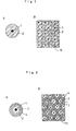
- Fig. 1 A shows a schematic cross section of a coated diamond particle used in the Examples.
- Fig. 1 B shows a schematic cross section of a compact used in the Example.
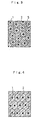
- Figs. 2 A and B show schematic cross section of other embodiments of this invention the same as Figs. 1 A and B.
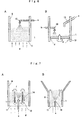
- Fig. 3 shows a schematic cross section of other embodiments of a coMPact used for synthesizing diamond.
- Fig. 4 shows other embodiments of a coMPact the same as Fig. 3.
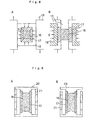
- Fig. 5 A shows a schematic cross section of a compact in which coated particles are compacted in a mono-layer.
- Fig. 5 B shows a schematic cross section of the mono-layer coMPact stacked with other fillers in a synthesizing vessel.
- Fig. 6 A schematic showing a method of coating with sprayed powder in a fluidized bed.
- Fig. 6 B schematically showing a method of coating with sprayed powder on a horizontally rotating disk.
- Fig. 7 A schematic showing Wurster type fluidized bed with an inner cylinder.
- Fig. 7 B schematic showing Wurster type fluidized bed with broder portion at upper parts.
- Fig. 8 A schematic showing a wet-cold-isostatic-press.
- Fig. 8 B schematic showing a dry-cold-isostatic-press.
- FIG. 9 A schematic showing an example of a supporting case
- Fig. 9 B showing another example.
- Fig. 10 A schematic showing a one-axis type.
- Fig. 10 B schematic showing a multi-axes type of ultra-high pressure apparatus for synthesizing diamond.
- Fig. 11 A schematic showing diamond particles having a lack portion.
- Fig. 11 B schematic showing diamond particles having poor symmetry.
- Figs. 12 A and B show prior art arrangements of powder method and multilayer method in synthesizing vessels.
- Fig. 13 shows another prior art arrangement in synthesizing vessels, namely, regularly arranged seed crystals in multilayer.
- Fig. 14 shows a schematic cross section of steel capsule for measuring impact strength.
- the present inventors have considered to solve the above issues, and have focused on the method of using compacted raw material which is made from each fine seed crystal (fine single crystal diamond) being coated with sufficient amounts of raw carbon powder and solvent metal powder. Sufficient amount means that the coated seed crystals are large enough so that grown diamond particles do not contact each other. Therefore, it is fundamentally required that the coated seed crystals are larger than the intended synthesized diamond partilces.
- the coated crystals When the coated crystals are compacted, the pore in the coated crystals is broken and the distance between the seed crystals decreases.
- the open space among the seed crystals decreases.
- the size of the coated seed crystal is far larger than the intended synthesized diamond particles.
- this invention remarkably improves the yield amount and strength of diamond coMPared with prior arts.
- the most fundamental constitution of this invention is comprised of using a compact 15, as shown in Fig. 1 B of fine seed crystals 1 coated with the mixture of raw carbon powder and solvent metal powder, as shown in Fig. 1 A.
- the same results can be obtained in using the coMPact 15, as shown in Fig. 2 B of fine seed crystals 1 coated with solvent metal layer 3, mixture layer 2 and a carbon layer 4 as shown in Fig. 2 A.
- the coated layer includes raw carbon and solvent metal. But solely raw carbon is not preferable for the innermost layer, because the seed crystals grow large with their change from carbon to diamond, namely through solvent metal.
- the second and outer layers are optionally selected.
- multilayer coated seed crystals such as, seed crystal/solvent metal/raw carbon/solvent metal/ raw carbon, or seed crystal/solvent metal/mixture of raw carbon and solvent metal/raw carbon, can also be used.
- each layer can be changed to different mixture ratios of raw carbon and solvent metal and different kinds of solvent metals.
- the compacted mixture of these coated crystals, raw carbon powder and / or solvent metal powder is industrially available. It is possible to decrease the amount of the coated material as much as the mixed amount of the raw carbon powder and / or the solvent metal powder. But it is indispensable in this method, as shown in Fig. 3 that there are contacting and not contacting areas between the coated particles depending on the condition of the added powder 5. Distances between the seed crystals vary in proportion to the added powder. When powder is added too much (the coated amount is too little), there is little improvement compared with the powder method. In assessing the advantage of the present invention, therefore, the true volume of the coated particles (the amount of seed crystals, raw carbon and solvent metal excluding pore and organic bonding material) must be at least 20 volume %. When the mixed powder includes raw carbon in this method, it is not necessary to include raw carbon in the coated particles.
- the thickness and composition of the coated layer and the amount and composition of the mixed powder are determined by considering the intended diamond particle size, distance between seed crystals, amount of raw carbon and solvent metal, compaction method and deformation of compact at synthesized condition of diamond in all of the above methods.
- Seed crystals, raw carbon and solvent metal which are used in the present invention are the same as those used in the prior technique.
- the seed crystal is usually in the range of 10 ⁇ 200 ⁇ m diameter since large seed crystal is liable to contain inclusions (impurities) : seed crystal is preferably very fine because it handles easily. When a seed crystal is too small, it is difficult to handle. But seed crystal should be single crystal. Any usual graphite can be used as raw carbon.
- the combination of Fe, Co, Ni, Cr and Mn (each material, alloy or mixture) which are used in the prior technique, can also be used as solvent metal.
- the coated with sprayed powder method was the simplest, easiest and most cost-efficient method.
- This method has been widely used in the field of producing pharmacies and foods.
- This method is carried out by spraying the mixture of solvent metal powder, raw carbon powder, organic bonding material and organic solvent from the spraying nozzle 10 to the fine single crystal diamonds 1 or semi-coated single crystal diamonds (hereafter defined as "core particle" ) as shown in Fig. 6A in which a core particle is fluidized or as shown in Fig. 6B in which a core particle is stirring.
- 9 is the outer cylinder of the coating equipment, 11 is porous plate, 12 is horizontally rotating disk, 13 is supply tube for powder, (a) is flow of slurry which contains powder to be coated/organic bonding material/organic solvent, (b) is flow of organic bonding material/organic solvent, (c) is flow of powder to be coated , (d) is flow of gas to dry the coated powder and (e) shows rotating direction of horizontally rotating disk.
- Adherent ratio of the supplied powder sometimes depends on the kind and particle size of the powder.
- the supplied mixture of 80:20 (weight ratio) of Ni:graphite became a composition of 75:25(weight ratio) in coated layer. It is necessary to investigate the adherent ratio and the composition of the coated layer prior to the experiments.
- Particle diameter of the powder is preferably smaller than 1/10 of a core particle diameter. It is usual that the smaller diameter and lighter weight of the powder, the better adherence of the powder to the core particle.
- the most preferable method is using Wurster type fluidizing bed in the coated with sprayed powder method.
- the seed crystals are cohered in other methods. That is coated particles randomly contain more than one seed crystal and such particles must be removed. On the other hand, such particles are seldom found when Wurster type fluidizing bed is used. Since the Wurster type fluidizing bed has an inner cylinder 14 as shown in Fig. 7 A or has a broader portion at the upper part as shown in Fig. 7 B, the particle decreases the velocity at the upper part and falls down along the outer cylinder 9. As the particles flow out in one direction and regularly circulate, cohesion rarely occurs.
- (a) is the flow of slurry which contains powder to be coated/organic bonding material/organic solvent
- (d) is the flow of drying gas
- (f) is the flow of core particles.
- the organic bonding material Before going in to detail, the organic bonding material must necessarily be removed by heat treatment before or after compaction. Especially when the organic bonding material is included excessively, most of it should be removed before compaction. When it is removed after compaction, the filled amount in the diamond synthesized vessel decreases since a pore remains in a compact.
- the removal temperature depends on the kind of organic bonding material and is about 300 ⁇ 600°C.
- the heat treatment should be carried out in a reduced or an inert atmosphere in order to prevent oxidation.
- an organic bonding material include an amount of organic lubricant in which removing temperature is higher than the organic bonding material.
- organic lubricant most of the organic material is removed at comparatively low temperature and compacting and then a small amount of the remainder (organic lubricant) is removed at coMParatively high temperature.
- the density of the compact increases after the processes of heat treatment at 400°C and compacting and then heat treatment at 600°C. In order to increase the strength of the compact, treating at higher than 600°C is considered. A reduced atmosphere is suggested since solvent metal is reduced.
- a one-axis ultra-high pressure apparatus is explained in Fig. 10A, which is used widely in industry.
- the synthesized vessel of this apparatus is usually a circular column, so a compact is basically molded into a circular column.
- the distance between seed crystals is the same as the size of a coated particle in radial direction, but decreases in proportion to compacted length in axial direction.
- the following phenomena occur in the ultra-high pressure apparatus.
- the distance between the seed crystals in radial direction is relatively shorter than in the axial direction as shown in Fig. 4.
- the present inventors have succeeded in using a dry-cold-isostatic-press apparatus or a method of pseudo-dry-cold-isostatic-press with a wet-cold-isostatic-press apparatus.
- the compact is uniformly compacted from all directions, as shown in Fig. 8A in normal use of a wet-cold-isostatic-press apparatus which is widely used as an apparatus of cold-isostatic-press.
- the compact is pressed only from the radial direction with a dry-cold-isostatic-press apparatus as shown in Fig.8B.
- the apparatus When the wet-cold-isostatic-press apparatus is used with a supporting case having side holes which controls pressing in the axial direction by side pores as shown in Fig.9A, the apparatus has the same properties as the dry-cold-isostatic-press apparatus (this is defined as "pseudo-dry-cold-isostatic-press).
- Compaction ratio of a radial direction and an axial direction can be controlled by pore ratio in coated particle and filled ratio in a compaction mold.
- the pore ratio has an especially important role on the compaction ratio and can be controlled by the amount of organic bonding material as mentioned before.
- the volume of organic bonding material is considered to be pore in the coated particles when the coated particles are dewaxed before compaction. It is carried out by increasing the amount of organic bonding material that is intended for compaction in the radial direction. In many cases, adequate distance ratio of seed crystal can be obtained by controlling the size and pore ratio of coated particle and using the dry or pseudo-dry-cold-isostatic-press.
- Figs. 8, 9 and 10,16 stands for particles to be compacted
- 17 stands for rubber molding
- 18 stands for liquid pressure medium
- 19 stands for steel vessel
- 20 stands for a metal lid
- 21 stands for supporting case.
- 22 stands for synthesizing vessel of diamond
- 23 stand for die made of cemented carbide
- 24 stands for anvil made of cemented carbide
- 25 stands for ceramie pressure medium
- 26 stands for electro conductive parts
- 27 stands for graphite heater.
- (g) stands for a compacting direction in a cold-isostatic-press apparatus and
- (h) stands for a compacting direction in a ultra-high-pressure apparatus.
- the multilayer method can be applicable to synthesize diamond particles using these coated particles.
- the method uses single layer compact of coated particles with raw carbon plate and solvent metal plate as shown in Fig.5A.
- the single layer compact is preferably combined with raw carbon and/or solvent metal layer as shown in Fig. 5B.
- the distance between the seed crystals in thickness direction is kept and controlled by the plate of raw carbon 7 and / or solvent metal 6. Therefore, the amount of coated raw carbon and solvent metal should be maintained to have sufficient distance between seed crystals in the single layer. It is preferable the simplest to make a single layer compact with a metal die.
- the following method is suggested in handling the single layer compact.
- the plate of raw carbon or solvent metal is coated with organic adhesive and the coated particles are arranged and adhered to the plate and then the combination is compacted as it is.
- the organic adhesive and organic bonding material should be removed by heat treatment prior to synthesizing diamond.
- this invention Comparing with the conventional multilayer method, especially seed crystals arranged orderly in a layer, this invention is advantageous in that the seed crystals do not move under even the condition of synthesizing diamond, because each seed crystal is surrounded by solid raw carbon. Synthesized diamond particles have remarkable strength compared with the conventional method. Since the amount of yield is the same as the conventional multilayer method, it is suggested that the above invented compact be used in the multilayer method. Such method, therefore, has high industrial applicability because the coating amount can decrease, a small amount of coated diamond particles is used and isostatic-press apparatus is not needed.
- diamond which is produced by using invented coated particle, has a small lack portion, good symmetry and high strength. Therefore the diamond is applicable to not only abrasive sawing but also to a diamond wheel and a dresser.
- the method of producing the coated particle is preferable to industrial use, because composition, particle size and pore ratio of a coated layer are controlled by selected fine diamond particle and powder to be coated.
- Single crystal diamond particles having the size of 325/400 mesh were coated with sprayed slurry which consisted of raw carbon/solvent metal/organic bonding material/organic solvent, using the apparatus shown in Fig. 7A.
- the raw carbon was graphite powder
- organic bonding materials were acrylic copolymer and polyethylene glycol
- organic solvent was isopropanol.
- the coating was stopped when the coated particles became about 800 ⁇ m diameter.
- Coated particles having 750 ⁇ 810 ⁇ m diameter were obtained by sieving and organic bonding material was removed in hydrogen stream at 450°C for 60 minutes. The particles were compacted into a circular column under a pressure of 3000kgf/cm 2 (294MPa) applying the case as shown in Fig. 9A to the apparatus of Fig. 8 A.
- the circular column compact was cut and pressed in a metal die under a pressure of 6000kgf/cm 2 (588MPa)in the axial direction and then heated in hydrogen stream at 1000°C for 60 minutes.
- the apparent density of the compact was 85% of theoretical density.
- the compact was worked into a circular column of 25mm diameter and 20mm height, and then the circular column was put into a one-axis ultra-high pressure apparatus as shown in Fig. 10A.
- the compact was exposed to the condition of 5.3 GPa and 1350°C for 30 minutes, and diamond particles were obtained.
- the yielded amount of diamond particles was 7.6 grams and particles of 5.2 grams out of 7.2 grams had a size of 40/50 mesh. Particles of 4.4 grams out of 5.2 grams had no lack portion, good symmetry and high strength.
- the measuring method of strength and comparative examples are summarized after the examples.
- Single crystal diamond particles having the size of 230/270 mesh were coated with raw carbon/solvent metal using the apparatus shown in Fig. 6B. Dry gas stirred the particles to a certain extent, because the horizontall rotating disk 12 was porous plate.
- the mixture of raw carbon powder/solvent metal powder and organic solvent dissolving organic bonding material were alternately sprayed from nozzles 10 and 13.
- Organic bonding materials were acrylic copolymer and ethyl cellulose, and organic solvent was ethanol. Acrylic copolymer and ethyl cellulose in the ethanol was 10 wt% and 2wt%. Nitrogen gas of 50°C was used as dry gas.
- the compact was exposed for 45 minutes using the same apparatus under the same condition as Example 1.
- the amount of yielded diamond was 6.4 grams, and 4.2 grams out of 6.4 grams had a size of 30/40 mesh. Particles of 3.2 grams were high strength diamond.
- a compact was obtained in the same manner as described in Example 2 and the apparent density of the compact after heat treatment and working was 89% of theoretical density.
- Diamond was synthesized in the same manner as described in Example 1, the amount of yielded diamond was 7.8 grams and 4.8 grams out of 7.8 grams had a size of 40/50 mesh. Particles of 3.4 grams was high strength diamond.
- Single crystal diamond particles having the size of 140/170 mesh were plated with Co by electroless plating, and grew to about 150 ⁇ m in diameter.
- the coated particles were compacted into a circular column compact under a pressure of 3000kgf/cm 2 (294MPa) applying the case as shown in Fig. 9A to the apparatus of Fig. 8 A, the compact was heated at 1050°C in hydrogen stream for 30 minutes.
- the apparent density of the compact was 82% of theoretical density.
- the compact was worked into the same size circular column as Example 1 and exposed to the condition as described in Example 1 for 15 minutes.
- the amount of yielded diamond was 7.3 grams and 5.4 grams out of 7.3 grams had a size of 50/60 mesh , and 4.8 grams out of 5.4 grams was high-strength particles.
- Coated particles were produced as described in Example 1. The coating was stopped at a little smaller than 500 ⁇ m in diameter. Particles having 425 ⁇ 500 ⁇ m diameter were selected and heated at 450°C in hydrogen stream for 60 minutes to remove organic bonding material.
- the particles were arranged in a mono-layer with the most close-packed in a one-axis compacting die, and compacted into plate compact of 22mm diameter and 135 ⁇ m thickness under the pressure of 2000kgf/cm 2 (196MPa).
- a 58 wt% Fe-42 wt% Ni alloy plate having 22mm diameter and 100 ⁇ m thickness and a graphite plate of 22mm diameter and 400 ⁇ m thickness were prepared. These plates were combined in the order of (Fe-Ni alloy plate) / (plate compact) / (Fe-Ni alloy plate)/(graphite plate) as shown in Fig. 5B.
- Example 2 It was exposed to the same conditions as Example 1 to synthesize diamond in that the multilayer plates were composed of the number of 20 compact plates, the number of 40 Fe-Ni alloy plates and the number of 21 graphite plates.
- the amount of yielded diamond was 3.6 grams and 2.4 grams out of 3.6 grams had a size of 40/50 mesh, and 2.0 grams out of 2.4 grams was high strength particles.
- the compact was heated at 1100°C in hydrogen for 60 minutes, and then worked as described in Example 1.
- the apparent density of the compact was 86% of theretical density.
- the compact was exposed under the conditions described in Example 1, but the keeping time was 60 minutes to synthesize diamond.
- the amount of yielded diamond particles were 6.0 grams and 3.4 grams out of 6.0 grams were a size of 20/25 mesh, and 1.9 grams out of 3.4 grams were high strength particles.
- the particles having 710 ⁇ 840 ⁇ m in diameter were selected and heated at 600°C in mixed gas of 10vol% hydrogen and 90vol% nitrogen for 30 minutes to remove the organic bonding material. These particles were molded into a circular column compact under the pressure of 2500kgf/cm 2 (245MPa)as the same manner as Example 6. The compact was heated at 1100°C in 100 torr of reduced pressure of hydrogen for 60 minutes, and then worked as described in Example 1. The apparent density of the compact was 83% of theoretical density. Diamond particles were synthesized as described in Example 1. The amount of yielded diamond particle were 7.2 grams, 4.9 grams of which were a size of 40/50 mesh and 3.9 grams out of 4.9 grams were high strength diamond particles. But the inclusions around the seed crystals were remarkably reduced compared with Example 1.
- the particles having 180 ⁇ 210 ⁇ m in diameter were selected.
- the following steps such as removing organic bonding material, compaction, heat treatment, working and synthesizing diamond, were carried out as described in Example 6.
- the amount of yielded diamond particles was 7.5 grams and 5.1 grams out of 7.9 grams were a size of 40/50 mesh and 4.4 grams out of 5.1 grams were high strength particles.
- the inclusions around the seed crystals were remarkably reduced and appeared to reduce beyond Example 7.
- Example 6 After the particles were coated aiming at 800 ⁇ m in diameter, the particles having 710 ⁇ 840 ⁇ m in diameter were selected. The following steps such as removing organic bonding material, coMPaction, heat treatment, working and synthesizing diamond, were carried out as described in Example 6. The amount of yielded diamond particles was 7.5 grams, 4.9 grams of which were a size of 40/50 mesh and 4.1 grams out of 4.9 grams were high strength diamond particles. The inclusion around the seed crystals appears to be the same extent as Example 8.
- the method is explained hereafter on the assumption that the object of diamond particles is a size of 40/50 mesh and approximately the same size of diamond particles are manufactured.
- the amount of A gram of manufactured diamond particles are sieved and B gram of a size of 40/50 mesh is obtained. Examples 1, 3, 5, 7, 8 and 9 correspond to this assumption.
- the following amount of diamond particles out of B gram in each example are put into the steel capsule(31) for measuring impact strength as shown in Fig. 14, and shaked with a steel ball(32) under the following condition.
- inner volume of the capsule about 2.5CC diameter of steel ball 5/16 inch number of steel ball 1 revolutions of steel capsule 2400rpm amplitude of vibration about 8 mm shaking time about 50 second amount of diamond 2ct(0.4g)
- the shaked diamond particles are removed from the capsule and sieved by estimation sieve of 302 ⁇ m.
- Weight % of the amount under the estimation sieve is the crushed ratio and this % is called crushability.
- weight % of the amount over the estimation sieve is called strength or toughness.
- the strength of each above example is shown in Table 1 and is stronger than comparative Example which is put on the market.
- the meaning of "after heat treatment” is that the value is measured at room temperature after heat treatment of 1100°C X 30 minutes in vacuum.
- Example 1 #40/50 (300 ⁇ 425 ⁇ m) 302 ⁇ m 84 79
- Example 3 #40/50 (300 ⁇ 425 ⁇ m) 302 ⁇ m 81 78
- Example 5 #40/50 (300 ⁇ 425 ⁇ m) 302 ⁇ m 82 77
- Example 7 #40/50 (300 ⁇ 425 ⁇ m) 302 ⁇ m 84 82
- Example 8 #40/50 (300 ⁇ 425 ⁇ m) 302 ⁇ m 85 84
- Example 9 #40/50 (300 ⁇ 425 ⁇ m) 302 ⁇ m 84 81 CoMParative Example 1 #40/50 Popular Grade on Market 302 ⁇ m 70-75 60-70 CoMParative Example 2 #40/50 High Grade on Market 302 ⁇ m 75-80 70-77 CoMParative Example 3 #40/50 Highest Grade on Market 302 ⁇ m 85 83
Landscapes
- Chemical & Material Sciences (AREA)
- Organic Chemistry (AREA)
- Chemical Kinetics & Catalysis (AREA)
- Carbon And Carbon Compounds (AREA)
- Crystals, And After-Treatments Of Crystals (AREA)
- Glanulating (AREA)
Claims (9)
- Verfahren zur Synthetisierung von Diamant, das die folgenden Schritte umfasst:(a) Beschichtung feiner Diamantteilchen mit mindestens einer Schicht, die ein Nicht-Diamant-Kohlenstoffmaterial, ein Lösungsmittel-Metallpulver und gegebenenfalls ein organisches Bindermaterial in einer oder mehreren der mindestens einen Schicht(en) umfasst, so dass die resultierenden beschichteten Teilchen eine Grösse aufweisen, die grösser ist als die beabsichtigte Grösse des herzustellenden synthetischen Diamants,(b) Kompaktierung der beschichteten Teilchen in einer solchen Weise, dass sie zumindest in teilweisem Kontakt miteinander stehen, gegebenenfalls zusammen mit einem Pulver, das zusätzliches Kohlenstoffrohmaterial und/oder Lösungsmittel-Metallpulver umfasst,(c) falls in Schritt (a) ein organisches Bindermaterial aufgeschichtet wird, Entfernen desselben vor oder nach dem Kompaktierungsschritt (b) durch Wärmebehandlung, und(d) Anordnung des kompaktierten Materials in einem Synthesekessel und Erwärmen desselben auf eine Temperatur oberhalb des Lösungsmittelmetall-Graphitschmelzpunkts bei einem Druck, bei dem Diamant thermodynamisch stabil ist.
- Verfahren zur.Synthese von Diamant, das die folgenden Schritte umfasst:die Schritte (c) und (d) wie in Anspruch 1.(a) Beschichtung feiner Diamantteilchen mit mindestens einer Schicht, umfassend ein Lösungsmittel-Metallpulver und gegebenenfalls ein organisches Bindermaterial in einer oder mehreren der mindestens einen Schicht(en), so dass die resultierenden beschichteten Teilchen eine Grösse aufweisen, die grösser ist als die beabsichtigte Grösse des herzustellenden synthetischen Diamants,(b) Kompaktierung der beschichteten Teilchen zusammen mit einem Pulver, das zusätzliches Kohlenstoffrohmaterial umfasst, in einer solchen Weise, dass die beschichteten Teilchen zumindest teilweise miteinander in Kontakt sind, gegebenenfalls zusammen mit einem Pulver, das zusätzliches Lösungsmittel-Metallpulver umfasst, und
- Verfahren gemäss mindestens einem der Ansprüche 1 bis 2, worin das organische Bindermaterial ein AcrylCopolymer enthält.
- Verfahren gemäss mindestens einem der Ansprüche 1 bis 3, worin Schritt (a) nach einem Sprühverfahren durchgeführt wird.
- Verfahren gemäss mindestens einem der Ansprüche 1 bis 4, worin Schritt (a) unter Verwendung eines Wurster-Typ-Fliessbetts oder einer horizontalen Drehscheibenausrüstung durchgeführt wird.
- Verfahren gemäss mindestens einem der Ansprüche 1 bis 4, worin die Entfernung des organischen Bindermaterials in Schritt (c) durch Erwärmen auf eine Temperatur von 300 bis 600°C durchgeführt wird.
- Verfahren gemäss Anspruch 6, worin das Erwärmen in einer reduzierenden oder einer inerten Atmosphäre durchgeführt wird.
- Verfahren gemäss mindestens einem der Ansprüche 1 bis 7, worin die Kompaktierung in Schritt (b) unter Verwendung einer kalt-isostatischen Presse durchgeführt wird.
- Verfahren gemäss Anspruch 8, worin das Pressen durch pseudo-trockene kalt-isostätische Pressung unter Verwendung einer nass-kalt-isostatischen Presse oder einer trocken-kalt-isostatischen Presse durchgeführt wird.
Applications Claiming Priority (6)
| Application Number | Priority Date | Filing Date | Title |
|---|---|---|---|
| JP11378495 | 1995-04-13 | ||
| JP113784/95 | 1995-04-13 | ||
| JP11378495 | 1995-04-13 | ||
| JP46603/96 | 1996-02-07 | ||
| JP4660396 | 1996-02-07 | ||
| JP8046603A JPH08337498A (ja) | 1995-04-13 | 1996-02-07 | ダイヤモンド粒子、ダイヤモンド合成用粒子及び圧密体並びにそれらの製造方法 |
Publications (3)
| Publication Number | Publication Date |
|---|---|
| EP0737510A2 EP0737510A2 (de) | 1996-10-16 |
| EP0737510A3 EP0737510A3 (de) | 1997-04-02 |
| EP0737510B1 true EP0737510B1 (de) | 2001-07-11 |
Family
ID=26386699
Family Applications (1)
| Application Number | Title | Priority Date | Filing Date |
|---|---|---|---|
| EP96105789A Expired - Lifetime EP0737510B1 (de) | 1995-04-13 | 1996-04-12 | Überzogene Teilchen zur Herstellung von Diamanten und Verfahren zur Herstellung von Diamantschleifkörpern zum Sägen |
Country Status (5)
| Country | Link |
|---|---|
| US (1) | US5980982A (de) |
| EP (1) | EP0737510B1 (de) |
| JP (1) | JPH08337498A (de) |
| KR (1) | KR0170805B1 (de) |
| DE (1) | DE69613741T2 (de) |
Families Citing this family (53)
| Publication number | Priority date | Publication date | Assignee | Title |
|---|---|---|---|---|
| US9409280B2 (en) | 1997-04-04 | 2016-08-09 | Chien-Min Sung | Brazed diamond tools and methods for making the same |
| US9238207B2 (en) | 1997-04-04 | 2016-01-19 | Chien-Min Sung | Brazed diamond tools and methods for making the same |
| US9463552B2 (en) | 1997-04-04 | 2016-10-11 | Chien-Min Sung | Superbrasvie tools containing uniformly leveled superabrasive particles and associated methods |
| US7368013B2 (en) * | 1997-04-04 | 2008-05-06 | Chien-Min Sung | Superabrasive particle synthesis with controlled placement of crystalline seeds |
| US7323049B2 (en) | 1997-04-04 | 2008-01-29 | Chien-Min Sung | High pressure superabrasive particle synthesis |
| US7404857B2 (en) * | 1997-04-04 | 2008-07-29 | Chien-Min Sung | Superabrasive particle synthesis with controlled placement of crystalline seeds |
| US9221154B2 (en) | 1997-04-04 | 2015-12-29 | Chien-Min Sung | Diamond tools and methods for making the same |
| US9199357B2 (en) | 1997-04-04 | 2015-12-01 | Chien-Min Sung | Brazed diamond tools and methods for making the same |
| US9868100B2 (en) | 1997-04-04 | 2018-01-16 | Chien-Min Sung | Brazed diamond tools and methods for making the same |
| DE19844397A1 (de) * | 1998-09-28 | 2000-03-30 | Hilti Ag | Abrasive Schneidkörper enthaltend Diamantpartikel und Verfahren zur Herstellung der Schneidkörper |
| US6627168B1 (en) * | 1999-10-01 | 2003-09-30 | Showa Denko Kabushiki Kaisha | Method for growing diamond and cubic boron nitride crystals |
| JP3957632B2 (ja) * | 2000-10-12 | 2007-08-15 | エレメント シックス (プロプライエタリイ)リミテッド | 多結晶質研磨性粗粒子 |
| US6979357B2 (en) | 2000-11-09 | 2005-12-27 | Mehmet Serdar Ozbayraktar | Method of producing ultra-hard abrasive particles |
| US6616725B2 (en) * | 2001-08-21 | 2003-09-09 | Hyun Sam Cho | Self-grown monopoly compact grit |
| JP2005524515A (ja) * | 2002-04-25 | 2005-08-18 | ザ・モーガン・クルーシブル・カンパニー・ピーエルシー | 触媒を用いたダイヤモンドの製造方法および合成において使用されるグラファイト/触媒混合物の加工方法 |
| EP1585500B8 (de) * | 2002-12-20 | 2017-07-26 | Auritec Pharmaceuticals | Beschichtete partikel für arzneimittelverabreichung mit verzögerter freisetzung |
| WO2004058222A1 (en) * | 2002-12-20 | 2004-07-15 | St. James Associates Llc/Faber Research Series | High pressure compaction for pharmaceutical formulations |
| AU2005213530A1 (en) * | 2004-01-15 | 2005-08-25 | Element Six Limited | Coated abrasives |
| US8454714B2 (en) * | 2004-03-01 | 2013-06-04 | Chien-Min Sung | Diamond growth devices and methods |
| AU2005335208B2 (en) * | 2004-09-10 | 2010-06-24 | Carnegie Institution Of Washington | Ultratough CVD single crystal diamond and three dimensional growth thereof |
| US8393934B2 (en) | 2006-11-16 | 2013-03-12 | Chien-Min Sung | CMP pad dressers with hybridized abrasive surface and related methods |
| US8622787B2 (en) | 2006-11-16 | 2014-01-07 | Chien-Min Sung | CMP pad dressers with hybridized abrasive surface and related methods |
| US9724802B2 (en) | 2005-05-16 | 2017-08-08 | Chien-Min Sung | CMP pad dressers having leveled tips and associated methods |
| US8398466B2 (en) | 2006-11-16 | 2013-03-19 | Chien-Min Sung | CMP pad conditioners with mosaic abrasive segments and associated methods |
| US8678878B2 (en) | 2009-09-29 | 2014-03-25 | Chien-Min Sung | System for evaluating and/or improving performance of a CMP pad dresser |
| US9138862B2 (en) | 2011-05-23 | 2015-09-22 | Chien-Min Sung | CMP pad dresser having leveled tips and associated methods |
| CN101247882B (zh) * | 2005-05-31 | 2012-09-05 | 六号元素(产品)(控股)公司 | 包覆金刚石晶种的方法 |
| JP4817848B2 (ja) * | 2006-01-12 | 2011-11-16 | 株式会社ライフ技術研究所 | 複合炭素膜および電子エミッタ |
| US9567506B2 (en) | 2007-07-23 | 2017-02-14 | Element Six Limited | Method for manufacturing encapsulated superhard material |
| WO2009013715A2 (en) * | 2007-07-23 | 2009-01-29 | Element Six Limited | Method for manufacturing encapsulated superhard material |
| TWI388402B (en) | 2007-12-06 | 2013-03-11 | Methods for orienting superabrasive particles on a surface and associated tools | |
| US9555387B2 (en) | 2008-02-14 | 2017-01-31 | Element Six Limited | Method for manufacturing encapsulated superhard material |
| WO2009101605A1 (en) * | 2008-02-14 | 2009-08-20 | Element Six Limited | Method for manufacturing encapsulated superhard material |
| US8252263B2 (en) | 2008-04-14 | 2012-08-28 | Chien-Min Sung | Device and method for growing diamond in a liquid phase |
| US9315881B2 (en) | 2008-10-03 | 2016-04-19 | Us Synthetic Corporation | Polycrystalline diamond, polycrystalline diamond compacts, methods of making same, and applications |
| US8297382B2 (en) | 2008-10-03 | 2012-10-30 | Us Synthetic Corporation | Polycrystalline diamond compacts, method of fabricating same, and various applications |
| US7866418B2 (en) | 2008-10-03 | 2011-01-11 | Us Synthetic Corporation | Rotary drill bit including polycrystalline diamond cutting elements |
| US8663349B2 (en) | 2008-10-30 | 2014-03-04 | Us Synthetic Corporation | Polycrystalline diamond compacts, and related methods and applications |
| KR101255615B1 (ko) * | 2009-01-29 | 2013-04-16 | 이화다이아몬드공업 주식회사 | 다이아몬드 공구용 세그먼트의 제조방법 및 제조된 세그먼트를 구비한 다이아몬드 공구 |
| US9205531B2 (en) | 2011-09-16 | 2015-12-08 | Baker Hughes Incorporated | Methods of fabricating polycrystalline diamond, and cutting elements and earth-boring tools comprising polycrystalline diamond |
| US10005672B2 (en) * | 2010-04-14 | 2018-06-26 | Baker Hughes, A Ge Company, Llc | Method of forming particles comprising carbon and articles therefrom |
| CN103221180A (zh) | 2010-09-21 | 2013-07-24 | 铼钻科技股份有限公司 | 具有基本平坦颗粒尖端的超研磨工具及其相关方法 |
| US9238875B2 (en) * | 2011-02-01 | 2016-01-19 | Sunset Peak International Limited | Multilayer structure for a diamond growth and a method of providing the same |
| WO2012162430A2 (en) | 2011-05-23 | 2012-11-29 | Chien-Min Sung | Cmp pad dresser having leveled tips and associated methods |
| RU2014114867A (ru) | 2011-09-16 | 2015-10-27 | Бейкер Хьюз Инкорпорейтед | Способы изготовления поликристаллического алмаза, а также режущих элементов и буровых инструментов, содержащих поликристаллический алмаз |
| GB201204533D0 (en) | 2012-03-15 | 2012-04-25 | Element Six Ltd | Process for manufacturing synthetic single crystal diamond material |
| GB201206883D0 (en) * | 2012-04-19 | 2012-06-06 | Element Six Ltd | Synthetic diamond crystals and method for making same |
| GB201222383D0 (en) * | 2012-12-12 | 2013-01-23 | Element Six Abrasives Sa | Diamond grains, method for making same and mixture comprising same |
| CN110013798A (zh) * | 2018-01-10 | 2019-07-16 | 河南烯碳合成材料有限公司 | 大钻石单晶的制造方法 |
| CN109234793A (zh) * | 2018-10-23 | 2019-01-18 | 营口鑫成达新型建材有限公司 | 一种合成单晶金刚石的方法 |
| CN111111558A (zh) * | 2020-01-08 | 2020-05-08 | 营口鑫成达新型建材股份有限公司 | 一种合成金刚石的方法 |
| CN112591744B (zh) * | 2021-01-15 | 2023-02-03 | 张相法 | 一种金刚石合成坯料及采用该坯料合成金刚石的方法 |
| CN112892411B (zh) * | 2021-01-25 | 2022-05-31 | 四川大学 | 一种高温高压下生长大颗粒金刚石的方法 |
Family Cites Families (9)
| Publication number | Priority date | Publication date | Assignee | Title |
|---|---|---|---|---|
| JPS5214685B2 (de) * | 1972-05-08 | 1977-04-23 | ||
| US4544540A (en) * | 1982-06-25 | 1985-10-01 | Sumitomo Electric Industries, Ltd. | Diamond single crystals, a process of manufacturing and tools for using same |
| JPS59164605A (ja) * | 1983-03-09 | 1984-09-17 | Showa Denko Kk | ダイヤモンド合成法 |
| JPS59164607A (ja) * | 1983-03-11 | 1984-09-17 | Showa Denko Kk | ダイヤモンド合成法 |
| US4547257A (en) * | 1984-09-25 | 1985-10-15 | Showa Denko Kabushiki Kaisha | Method for growing diamond crystals |
| US4770907A (en) * | 1987-10-17 | 1988-09-13 | Fuji Paudal Kabushiki Kaisha | Method for forming metal-coated abrasive grain granules |
| GB2242443B (en) * | 1990-03-28 | 1994-04-06 | Nisshin Flour Milling Co | Coated particles of inorganic or metallic materials and processes of producing the same |
| JP2546558B2 (ja) * | 1991-07-22 | 1996-10-23 | 住友電気工業株式会社 | ダイヤモンド砥粒の合成方法 |
| US5143523A (en) * | 1991-09-20 | 1992-09-01 | General Electric Company | Dual-coated diamond pellets and saw blade semgents made therewith |
-
1996
- 1996-02-07 JP JP8046603A patent/JPH08337498A/ja active Pending
- 1996-04-09 US US08/629,516 patent/US5980982A/en not_active Expired - Fee Related
- 1996-04-12 EP EP96105789A patent/EP0737510B1/de not_active Expired - Lifetime
- 1996-04-12 DE DE69613741T patent/DE69613741T2/de not_active Expired - Fee Related
- 1996-04-13 KR KR1019960011120A patent/KR0170805B1/ko not_active Expired - Fee Related
Also Published As
| Publication number | Publication date |
|---|---|
| EP0737510A3 (de) | 1997-04-02 |
| DE69613741D1 (de) | 2001-08-16 |
| US5980982A (en) | 1999-11-09 |
| EP0737510A2 (de) | 1996-10-16 |
| KR0170805B1 (ko) | 1999-01-15 |
| DE69613741T2 (de) | 2002-04-25 |
| JPH08337498A (ja) | 1996-12-24 |
Similar Documents
| Publication | Publication Date | Title |
|---|---|---|
| EP0737510B1 (de) | Überzogene Teilchen zur Herstellung von Diamanten und Verfahren zur Herstellung von Diamantschleifkörpern zum Sägen | |
| EP0626236B1 (de) | Verfahren zur Herstellung eines Schleifkörpers | |
| US7585366B2 (en) | High pressure superabrasive particle synthesis | |
| US6214079B1 (en) | Triphasic composite and method for making same | |
| EP0626237B1 (de) | Verfahren zur Herstellung eines Schleifkörpers | |
| KR101441153B1 (ko) | 피삭성이 향상된 연마 콤팩트 | |
| JP5456949B2 (ja) | 多結晶質立方晶窒化硼素の切削工具インサートの製造方法 | |
| US4547257A (en) | Method for growing diamond crystals | |
| US7368013B2 (en) | Superabrasive particle synthesis with controlled placement of crystalline seeds | |
| JP4405610B2 (ja) | スパッタリングターゲットの製造方法 | |
| US7404857B2 (en) | Superabrasive particle synthesis with controlled placement of crystalline seeds | |
| FI91271C (fi) | Menetelmä tahkoavan aineen tuottamiseksi ja menetelmällä tuotettu tahkoava keraaminen aine | |
| JP6949844B2 (ja) | 超硬合金材料の製造方法 | |
| US6090343A (en) | Triphasic composite and method for making same | |
| US9044726B2 (en) | Method of cladding diamond seeds | |
| US20100166635A1 (en) | Interrupted Diamond Growth | |
| WO2008025836A1 (en) | Granules for use in abrading or cutting tools production | |
| EP4541781B1 (de) | Verfahren zur herstellung eines grossen polykristallinen verbundrohlings mit diamantmatrix (pcdm) | |
| JPS6022680B2 (ja) | 工具用複合焼結体及びその製造方法 | |
| RU2053198C1 (ru) | Способ синтеза алмаза | |
| JPH01127602A (ja) | 焼結性および成形性にすぐれた粉末冶金用耐摩耗性合金鋼粉末 | |
| JPH05320812A (ja) | ダイヤモンド焼結体及び製造方法、並びにその製造の際に用いられる触媒 |
Legal Events
| Date | Code | Title | Description |
|---|---|---|---|
| PUAI | Public reference made under article 153(3) epc to a published international application that has entered the european phase |
Free format text: ORIGINAL CODE: 0009012 |
|
| AK | Designated contracting states |
Kind code of ref document: A2 Designated state(s): DE IE |
|
| PUAL | Search report despatched |
Free format text: ORIGINAL CODE: 0009013 |
|
| AK | Designated contracting states |
Kind code of ref document: A3 Designated state(s): DE IE |
|
| 17P | Request for examination filed |
Effective date: 19970404 |
|
| 17Q | First examination report despatched |
Effective date: 19990603 |
|
| GRAG | Despatch of communication of intention to grant |
Free format text: ORIGINAL CODE: EPIDOS AGRA |
|
| GRAG | Despatch of communication of intention to grant |
Free format text: ORIGINAL CODE: EPIDOS AGRA |
|
| GRAH | Despatch of communication of intention to grant a patent |
Free format text: ORIGINAL CODE: EPIDOS IGRA |
|
| GRAH | Despatch of communication of intention to grant a patent |
Free format text: ORIGINAL CODE: EPIDOS IGRA |
|
| GRAA | (expected) grant |
Free format text: ORIGINAL CODE: 0009210 |
|
| AK | Designated contracting states |
Kind code of ref document: B1 Designated state(s): DE IE |
|
| REF | Corresponds to: |
Ref document number: 69613741 Country of ref document: DE Date of ref document: 20010816 |
|
| REG | Reference to a national code |
Ref country code: IE Ref legal event code: FG4D |
|
| PGFP | Annual fee paid to national office [announced via postgrant information from national office to epo] |
Ref country code: DE Payment date: 20020417 Year of fee payment: 7 |
|
| PGFP | Annual fee paid to national office [announced via postgrant information from national office to epo] |
Ref country code: IE Payment date: 20020426 Year of fee payment: 7 |
|
| PLBE | No opposition filed within time limit |
Free format text: ORIGINAL CODE: 0009261 |
|
| STAA | Information on the status of an ep patent application or granted ep patent |
Free format text: STATUS: NO OPPOSITION FILED WITHIN TIME LIMIT |
|
| 26N | No opposition filed | ||
| PG25 | Lapsed in a contracting state [announced via postgrant information from national office to epo] |
Ref country code: IE Free format text: LAPSE BECAUSE OF NON-PAYMENT OF DUE FEES Effective date: 20030414 |
|
| PG25 | Lapsed in a contracting state [announced via postgrant information from national office to epo] |
Ref country code: DE Free format text: LAPSE BECAUSE OF NON-PAYMENT OF DUE FEES Effective date: 20031101 |
|
| REG | Reference to a national code |
Ref country code: IE Ref legal event code: MM4A |