EP0736727A1 - Beleuchtungseinrichtung für Fahrzeuge - Google Patents
Beleuchtungseinrichtung für Fahrzeuge Download PDFInfo
- Publication number
- EP0736727A1 EP0736727A1 EP96103742A EP96103742A EP0736727A1 EP 0736727 A1 EP0736727 A1 EP 0736727A1 EP 96103742 A EP96103742 A EP 96103742A EP 96103742 A EP96103742 A EP 96103742A EP 0736727 A1 EP0736727 A1 EP 0736727A1
- Authority
- EP
- European Patent Office
- Prior art keywords
- extension
- housing
- closure part
- inner channel
- lighting device
- Prior art date
- Legal status (The legal status is an assumption and is not a legal conclusion. Google has not performed a legal analysis and makes no representation as to the accuracy of the status listed.)
- Granted
Links
Images
Classifications
-
- F—MECHANICAL ENGINEERING; LIGHTING; HEATING; WEAPONS; BLASTING
- F21—LIGHTING
- F21S—NON-PORTABLE LIGHTING DEVICES; SYSTEMS THEREOF; VEHICLE LIGHTING DEVICES SPECIALLY ADAPTED FOR VEHICLE EXTERIORS
- F21S45/00—Arrangements within vehicle lighting devices specially adapted for vehicle exteriors, for purposes other than emission or distribution of light
- F21S45/30—Ventilation or drainage of lighting devices
- F21S45/33—Ventilation or drainage of lighting devices specially adapted for headlamps
Definitions
- the invention relates to a lighting device for vehicles according to the preamble of claim 1.
- Such a lighting device is known from DE 40 34 258 A1.
- This lighting device has a housing that at least partially delimits an interior of the lighting device in which at least one light source is arranged.
- the housing has at least one ventilation opening, in the area of which an extension protrudes outwards from the housing.
- An inner channel connected to the ventilation opening is formed on the extension and a closure part can be placed on the extension.
- the extension and the closure part form an outer channel, which is connected to the inner channel and the outside atmosphere.
- the closure part has an outer section surrounding the extension at least on a part of its circumference.
- a plurality of latching arms protrude outward from the housing and surround the extension, which engage the section of the closure part surrounding the extension and thereby hold the closure part in a latching manner on the housing.
- the housing is generally produced by injection molding from plastic, this type of latching connection of the closure part to the housing requiring complicated and complex tools for the production of the housing, which should be avoided.
- the closure part is removable from the housing and it is not ensured that the closure part does not unintentionally detach from the housing even in the event of strong vibrations or during maintenance work on the vehicle, so that splash water can penetrate into the interior of the lighting device.
- additional assembly effort would be required, for example for gluing the closure part.
- the lighting device according to the invention for vehicles has the advantage that the closure part can be fastened captively to the housing without additional assembly effort.
- the housing can be manufactured with simple tools by injection molding.
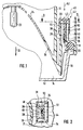
- FIG. 1 shows sections of a lighting device for vehicles and FIG. 2 shows the lighting device in a section along line II-II in FIG. 1.
- a lighting device for vehicles, in particular motor vehicles, shown only in sections in FIGS. 1 and 2, can be designed as a headlight or a lamp.
- the exemplary embodiment shown is a headlamp which has a housing 10 which is preferably made of plastic and is produced by injection molding.
- the cover plate 12 can be designed as a smooth plate or have optical elements.
- the cover disk 12 has a circumferential edge 16 with which it is fastened in a circumferential groove 18 on the front edge of the housing 10.
- the housing 10 has an aperture section 20 which is surrounded by the groove 18 and which projects in the light exit direction 22 into the peripheral edge 16 of the cover plate 12 and tapers conically in the opposite direction to the light exit direction 22.
- At least one light source 23 is arranged in the interior 14 of the headlight and can be inserted, for example, into a reflector 24, which is only shown in sections.
- a gap between the edge of the reflector 24 and the inside of the housing 10 is at least partially covered by the aperture section 20 of the housing 10.
- the housing 10 has at least one ventilation opening 26 through which the interior 14 is connected to the outside atmosphere.
- the ventilation opening 26 is arranged in an edge region of the housing 10 between its panel section 20 and the circumferential groove 18.
- the ventilation opening 26 is adjoined on the outside of the housing 10 by an inner channel 28 which is delimited by an extension 30 projecting outwards on the housing 10.
- the inner channel 28 and the extension 30 have a rectangular cross-sectional shape, as shown in FIG. 2, can also have any other cross-sectional shape.
- the extension 30 has, as shown in FIG. 2, two transverse walls 31 and two longitudinal walls 32, 33, one longitudinal wall 32 of the extension 30 being wider than the other longitudinal wall 33 of the extension 30.
- the wider longitudinal wall 32 of the extension 30 is in contact the edges of which point away from the longitudinal wall 33 two walls 34, between which an open channel running approximately parallel to the inner channel 28 is formed.
- the longitudinal wall 32 of the extension 30 protrudes from the housing 10 beyond the free end of the extension 30, which is determined by the ends of the two transverse walls 31 and the longitudinal wall 33 and the ends of the walls 34.
- the part of the longitudinal wall 32 projecting beyond the free end of the extension 30 does not extend over the full width of the longitudinal wall 32 but only approximately over the width of the longitudinal wall 33.
- the longitudinal wall 32 of the extension 30 delimiting the inner channel 28 projects into the inner one Channel 28 a projection 36 into it.
- the projection 36 is chamfered on its edge 38 pointing away from the ventilation opening 26 towards the longitudinal wall 32 and has on its edge facing the ventilation opening 26 a shoulder 39 arranged approximately perpendicular to the longitudinal wall 32.
- the free end of the extension 30 can be closed by means of a closure part in the form of a cap 42.
- the cap 42 has an outer section 44 with a cross-sectional shape adapted to the cross-sectional shape of the extension 30, and is therefore of rectangular design in the exemplary embodiment shown.
- the cap 42 has, in one piece with the outer portion 44, a base 46 and surrounded by the outer portion 44 a finger 48 with a flat cross section projects from the base 46.
- the finger 48 is resiliently pivotable transversely to the longitudinal axis 43 of the cap 42 and has a recess 49 in the form of a depression or opening near its free end.
- the cap 42 is pushed onto the extension 30 from the rear of the housing 10 in the direction of the arrow 52, its outer portion 44 surrounding the extension 30 on its circumference.
- the finger 48 of the cap 42 dips into the inner channel 28 and slides onto the projection 36 transversely to the mounting direction 52 over the edge 38, which slopes upwards in the mounting direction 52, under resilient pivoting.
- the bottom 46 thereof comes to rest in the mounting direction 52 on the free end of the longitudinal wall 32 projecting beyond the free end of the extension 30, whereby a free space remains between the free end of the extension 30 and the bottom 46 of the cap 42.
- the projection 36 dips into the recess 49 and the edge of the recess 49 engages on the shoulder 39 of the projection 36.
- the outer channel 44 of the cap 42 closes the open channel of the extension 30 delimited by the longitudinal wall 32 and the walls 34 and an outer channel 50 is formed.
- the outer portion 44 of the cap 42 does not extend to the rear of the housing 10, so that the channel to the housing 10 remains open.
- the outer channel 50 is connected to the inner channel 28 via the space remaining between the bottom 46 of the cap 42 and the free end of the extension 30 and between the longitudinal wall 32 and the outer section 44 of the cap 42.
- the inner channel 28 connected to the ventilation opening 26 is present on the extension 30 and the outer channel 50 connected to the inner channel 28 and via the open channel to the outside atmosphere.
- This configuration ensures that the inner space 14 is connected to the outside atmosphere without moisture, in particular splash water, being able to penetrate into the interior 14 from the outside.
- the housing 10 with the projection 30 formed thereon and the projection 36 arranged on the wall 32 and the cap 42 with the finger 48 formed thereon with the recess 49 can be injection molded using simple tools can be made from plastic. After the cap 42 is attached to the extension 30, it can no longer be released without being destroyed, since its finger 48 is arranged inside the extension 30 and is not accessible. For the captive fastening of the cap 42, no additional assembly effort is required, but it only needs to be pushed onto the extension 30.
- the projection 36 could also protrude outward from the longitudinal wall 32, that is to say into the open channel or the outer channel 50, in which case the finger 48 of the cap 42 is accordingly arranged such that it dips into the channel.
- the projection 36 could also be arranged on the other longitudinal wall 33 or on one of the transverse walls 31 of the extension 30 projecting into the inner channel 28, the finger 48 then also being arranged on the cap 42 accordingly.
Landscapes
- Engineering & Computer Science (AREA)
- General Engineering & Computer Science (AREA)
- Arrangement Of Elements, Cooling, Sealing, Or The Like Of Lighting Devices (AREA)
- Non-Portable Lighting Devices Or Systems Thereof (AREA)
Abstract
Description
- Die Erfindung geht aus von einer Beleuchtungseinrichtung für Fahrzeuge nach der Gattung des Anspruchs 1.
- Eine solche Beleuchtungseinrichtung ist durch die DE 40 34 258 A1 bekannt. Diese Beleuchtungseinrichtung weist ein Gehäuse auf, das zumindest teilweise einen Innenraum der Beleuchtungseinrichtung begrenzt in dem wenigstens eine Lichtquelle angeordnet ist. Das Gehäuse weist wenigstens eine Belüftungsöffnung auf, in deren Bereich vom Gehäuse ein Fortsatz nach außen absteht. Am Fortsatz ist ein mit der Belüftungsöffnung verbundener innerer Kanal gebildet und auf den Fortsatz ist ein Verschlußteil aufsetzbar. Durch den Fortsatz und das Verschlußteil ist ein äußerer Kanal gebildet, der mit dem inneren Kanal und der Außenatmosphäre verbunden ist. Das verschlußteil weist einen den Fortsatz zumindest auf einem Teil von dessen Umfang umgebenden Außenabschnitt auf. Vom Gehäuse stehen nach außen den Fortsatz umgebend mehrere Rastarme ab, die am den Fortsatz umgebenden Abschnitt des Verschlußteils angreifen und dadurch das Verschlußteil rastartig am Gehäuse halten. Das Gehäuse wird im allgemeinen durch Spritzgießen aus Kunststoff hergestellt, wobei diese Art der Rastverbindung des Verschlußteils mit dem Gehäuse komplizierte und aufwendig herzustellende Werkzeuge für die Herstellung des Gehäuses erfordert, was vermieden werden sollte. Außerdem ist das Verschlußteil wieder vom Gehäuse entfernbar und es ist nicht sichergestellt, daß das Verschlußteil sich nicht auch bei starken Erschütterungen oder bei Wartungsarbeiten am Fahrzeug unbeabsichtigt vom Gehäuse löst, so daß Spritzwasser in den Innenraum der Beleuchtungseinrichtung eindringen kann. Um das Verschlußteil verliersicher am Gehäuse zu befestigen wäre ein zusätzlicher Montageaufwand erforderlich, beispielsweise zum Verkleben des Verschlußteils.
- Die erfindungsgemäße Beleuchtungseinrichtung für Fahrzeuge hat demgegenüber den Vorteil, daß das Verschlußteil ohne zusätzlichen Montageaufwand verliersicher am Gehäuse befestigbar ist.
- In den abhängigen Ansprrüchen sind vorteilhafte Ausgestaltungen und Weiterbildungen der Erfindung angegeben. Durch die Ausbildung gemäß Anspruch 2 ist das Gehäuse mit einfachen Werkzeugen durch Spritzgießen herstellbar.
- Ein Ausführungsbeispiel der Erfindung ist in der Zeichnung dargestellt und in der nachfolgenden Beschreibung näher erläutert. Es zeigen Figur 1 abschnittsweise eine Beleuchtungseinrichtung für Fahrzeuge und Figur 2 die Beleuchtungseinrichtung in einem Schnitt entlang Linie II-II in Figur 1.
- Eine in den Figuren 1 und 2 nur abschnittsweise dargestellte Beleuchtungseinrichtung für Fahrzeuge, insbesondere Kraftfahrzeuge, kann als ein Scheinwerfer oder eine Leuchte ausgebildet sein. Beim dargestellten Ausführungsbeispiel handelt es sich um einen Scheinwerfer, der ein Gehäuse 10 aufweist, das vorzugsweise aus Kunststoff besteht und durch Spritzgießen hergestellt ist. Das Gehäuse 10 sowie eine an einem die Lichtaustrittsöffnung des Gehäuses 10 umgebenden Vorderrand des Gehäuses 10 befestigte Abdeckscheibe 12 begrenzen einen Innenraum 14 des Scheinwerfers. Die Abdeckscheibe 12 kann als glatte Scheibe ausgebildet sein oder optische Elemente aufweisen. Die Abdeckscheibe 12 weist einen umlaufenden Rand 16 auf, mit dem sie in einer umlaufenden Nut 18 am Vorderrand des Gehäuses 10 befestigt ist. Das Gehäuse 10 weist einen von der Nut 18 umgebenen Blendenabschnitt 20 auf, der in Lichtaustrittsrichtung 22 in den umlaufenden Rand 16 der Abdeckscheibe 12 ragt und sich entgegen Lichtaustrittsrichtung 22 konisch verjüngt. Im Innenraum 14 des Scheinwerfers ist wenigstens eine Lichtquelle 23 angeordnet, die beispielsweise in einen nur abschnittsweise dargestellten Reflektor 24 eingesetzt sein kann. Durch den Blendenabschnitt 20 des Gehäuses 10 wird ein zwischen dem Rand des Reflektors 24 und der Innenseite des Gehäuses 10 vorhandener Spalt zumindest teilweise verdeckt.
- Das Gehäuse 10 weist wenigstens eine Belüftungsöffnung 26 auf, durch die der Innenraum 14 mit der Außenatmosphäre verbunden ist. Die Belüftungsöffnung 26 ist in einem Randbereich des Gehäuses 10 zwischen dessen Blendenabschnitt 20 und der umlaufenden Nut 18 angeordnet. An die Belüftungsöffnung 26 schließt sich auf der Außenseite des Gehäuses 10 ein innerer Kanal 28 an, der durch einen am Gehäuse 10 nach außen abstehenden Fortsatz 30 begrenzt ist. Der innere Kanal 28 und der Fortsatz 30 weisen wie in Figur 2 dargestellt eine rechteckige Querschnittsform auf, können jedoch auch eine beliebige andere Querschnittsform aufweisen. Der Fortsatz 30 weist wie in Figur 2 dargestellt zwei Querwandungen 31 und zwei Längswandungen 32, 33 auf, wobei die eine Längswandung 32 des Fortsatzes 30 breiter ausgeführt ist als die andere Längswandung 33 des Fortsatzes 30. Von der breiteren Längswandung 32 des Fortsatzes 30 stehen an deren Rändern von der Längswandung 33 wegweisend zwei Wände 34 ab, zwischen denen eine etwa parallel zum inneren Kanal 28 verlaufende offene Rinne gebildet ist. Die Längswandung 32 des Fortsatzes 30 ragt vom Gehäuse 10 weg über das freie Ende des Fortsatzes 30 hinaus, das durch die Enden der beiden Querwandungen 31 und der Längswandung 33 sowie die Enden der Wände 34 bestimmt ist. Der über das freie Ende des Fortsatzes 30 hinausragende Teil der Längswandung 32 erstreckt sich dabei nicht über die volle Breite der Längswandung 32 sondern nur etwa über die Breite der Längswandung 33. Aus der den inneren Kanal 28 begrenzenden Längswandung 32 des Fortsatzes 30 ragt in den inneren Kanal 28 ein Vorsprung 36 hinein. Der Vorsprung 36 ist an seinem von der Belüftungsöffnung 26 wegweisenden Rand 38 zur Längswandung 32 hin angeschrägt und weist an seinem zur Belüftungsöffnung 26 weisenden Rand eine etwa senkrecht zur Längswandung 32 angeordnete Schulter 39 auf.
- Das freie Ende des Fortsatzes 30 ist mittels eines Verschlußteils in Form einer Kappe 42 verschließbar. Die Kappe 42 weist einen Außenabschnitt 44 auf, mit einer an die Querschnittsform des Fortsatzes 30 angepaßten Querschnittsform, ist also beim dargestellten Ausführungsbeispiel rechteckig ausgebildet. Die Kappe 42 weist einstückig mit dem Außenabschnitt 44 einen Boden 46 auf und vom Außenabschnitt 44 umgeben steht vom Boden 46 ein Finger 48 mit flachem Querschnitt ab. Der Finger 48 ist quer zur Längsachse 43 der Kappe 42 federnd schwenkbar und weist nahe seinem freien Ende eine Aussparung 49 in Form einer Vertiefung oder Öffnung auf.
- Zu ihrer Montage wird die Kappe 42 von der Rückseite des Gehäuses 10 her in Pfeilrichtung 52 auf den Fortsatz 30 aufgeschoben, wobei ihr Außenabschnitt 44 den Fortsatz 30 auf dessen Umfang umgibt. Der Finger 48 der Kappe 42 taucht in den inneren Kanal 28 ein und gleitet unter federnder Schwenkung quer zur Aufsetzrichtung 52 über den in Aufsetzrichtung 52 ansteigend angeschrägten Rand 38 auf den Vorsprung 36 auf. In der Endlage der Kappe 42 kommt deren Boden 46 in Aufsetzrichtung 52 am freien Ende der über das freie Ende des Fortsatzes 30 hinausragenden Längswandung 32 zur Anlage, wobei dadurch zwischen dem freien Ende des Fortsatzes 30 und dem Boden 46 der Kappe 42 ein Freiraum verbleibt. In der Endlage der Kappe 42 taucht der Vorsprung 36 in der Aussparung 49 ein und der Rand der Aussparung 49 rastet an der Schulter 39 des Vorsprungs 36 ein. Durch den Außenabschnitt 44 der Kappe 42 wird die durch die Längswandung 32 und die Wände 34 begrenzte offene Rinne des Fortsatzes 30 verschlossen und ein äußerer Kanal 50 gebildet. Der Außenabschnitt 44 der Kappe 42 reicht nicht bis zur Rückseite des Gehäuses 10, so daß die Rinne zum Gehäuse 10 hin offen bleibt. Über den zwischen dem Boden 46 der Kappe 42 und dem freien Ende des Fortsatzes 30 sowie den zwischen der Längswandung 32 und dem Außenabschnitt 44 der Kappe 42 verbleibenden Freiraum ist der äußere Kanal 50 mit dem inneren Kanal 28 verbunden.
- Bei der vorstehend beschriebenen Beleuchtungseinrichtung ist somit am Fortsatz 30 der mit der Belüftungsöffnung 26 verbundene innere Kanal 28 vorhanden und der mit dem inneren Kanal 28 und über die offene Rinne mit der Außenatmosphäre verbundene äußere Kanal 50. Durch diese Ausbildung ist sichergestellt, daß der Innenraum 14 mit der Außenatmosphäre verbunden ist, ohne daß von außen Feuchtigkeit, insbesondere Spritzwasser, in den Innenraum 14 eindringen kann. Das Gehäuse 10 mit dem an diesem angeformten Fortsatz 30 und dem an der Wandung 32 angeordneten Vorsprung 36 und die Kappe 42 mit dem an dieser angeformten Finger 48 mit der Aussparung 49 sind mit einfachen Werkzeugen durch Spritzgießen aus Kunststoff herstellbar. Nachdem die Kappe 42 auf dem Fortsatz 30 angebracht ist, kann diese nicht mehr ohne Zerstörung gelöst werden, da deren Finger 48 innerhalb des Fortsatzes 30 angeordnet ist und nicht zugänglich ist. Für die verliersichere Befestigung der Kappe 42 ist dabei kein zusätzlicher Montageaufwand erforderlich, sondern diese braucht nur auf den Fortsatz 30 aufgeschoben zu werden.
- Alternativ zur vorstehend beschriebenen Ausführung könnte der Vorsprung 36 aus der Längswandung 32 auch nach außen, das heißt in die offene Rinne oder den äußeren Kanal 50 hervorstehen, wobei dann der Finger 48 der Kappe 42 entsprechend so angeordnet ist, daß er in die Rinne eintaucht. Ebenso könnte der Vorsprung 36 auch an der anderen Längswandung 33 oder an einer der Querwandungen 31 des Fortsatzes 30 in den inneren Kanal 28 hineinragend angeordnet sein, wobei dann ebenfalls der Finger 48 entsprechend an der Kappe 42 angeordnet ist.
Claims (4)
- Beleuchtungseinrichtung für Fahrzeuge mit einem Gehäuse (10), durch das zumindest teilweise ein Innenraum (14) begrenzt wird, in dem wenigstens eine Lichtquelle angeordnet ist und das wenigstens eine Belüftungsöffnung (26) aufweist, in deren Bereich vom Gehäuse (10) ein Fortsatz (30) nach außen absteht, auf den ein Verschlußteil (42) aufsetzbar ist, wobei durch den Fortsatz (30) ein mit der Belüftungsöffnung (26) verbundener innerer Kanal (28) gebildet ist und durch den Fortsatz (30) sowie das Verschlußteil (42) ein mit dem inneren Kanal (28) und der Außenatmosphäre verbundener äußerer Kanal (50) gebildet ist, wobei das Verschlußteil (42) einen den Fortsatz (30) zumindest auf einem Teil von dessen Umfang umgebenden Außenabschnitt (44) aufweist und mittels einer Rastverbindung am Gehäuse (10) befestigbar ist, dadurch gekennzeichnet, daß das Verschlußteil (42) einen in den Fortsatz (30) hineinragenden Finger (48) aufweist, der quer zur Aufsetzrichtung (52) des Verschlußteils (42) federnd schwenkbar ist und der an einer innerhalb des Außenabschnitts (44) des Verschlußteils (42) angeordneten Wandung (32) des Fortsatzes (30) einrastbar ist.
- Beleuchtungseinrichtung nach Anspruch 1, dadurch gekennzeichnet, daß aus der Wandung (32) quer zur Aufsetzrichtung (52) des Verschlußteils (42) ein Vorsprung (36) hervorsteht und daß der Finger (48) eine Aussparung (49) aufweist, die am Vorsprung (36) einrastet.
- Beleuchtungsvorrichtung nach Anspruch 2, dadurch gekennzeichnet, daß die Wandung (32) den inneren Kanal (28) begrenzt und daß der Vorsprung (36) in den inneren Kanal (28) hineinragt.
- Beleuchtungseinrichtung nach Anspruch 2 oder 3, dadurch gekennzeichnet, daß der Vorsprung (36) an seinem entgegen der Aufsetzrichtung (52) des Verschlußteils (42) weisenden Rand (36) in Aufsetzrichtung (52) ansteigend angeschrägt ist und an seinem in Aufsetzrichtung (52) weisenden Rand eine etwa senkrecht zur Aufsetzrichtung (52) angeordnete Schulter (40) aufweist, an der der Rand der Aussparung (49) des Fingers (48) einrastet.
Applications Claiming Priority (2)
| Application Number | Priority Date | Filing Date | Title |
|---|---|---|---|
| DE19513369 | 1995-04-08 | ||
| DE19513369A DE19513369A1 (de) | 1995-04-08 | 1995-04-08 | Beleuchtungseinrichtung für Fahrzeuge |
Publications (2)
| Publication Number | Publication Date |
|---|---|
| EP0736727A1 true EP0736727A1 (de) | 1996-10-09 |
| EP0736727B1 EP0736727B1 (de) | 2004-09-01 |
Family
ID=7759249
Family Applications (1)
| Application Number | Title | Priority Date | Filing Date |
|---|---|---|---|
| EP96103742A Expired - Lifetime EP0736727B1 (de) | 1995-04-08 | 1996-03-09 | Beleuchtungseinrichtung für Fahrzeuge |
Country Status (4)
| Country | Link |
|---|---|
| US (1) | US5649762A (de) |
| EP (1) | EP0736727B1 (de) |
| JP (1) | JPH08287708A (de) |
| DE (2) | DE19513369A1 (de) |
Cited By (1)
| Publication number | Priority date | Publication date | Assignee | Title |
|---|---|---|---|---|
| EP3204687A2 (de) * | 2014-10-06 | 2017-08-16 | Automotive Lighting Reutlingen GmbH | Scheinwerfergehäuse und verfahren zum herstellen eines scheinwerfergehäuses |
Families Citing this family (1)
| Publication number | Priority date | Publication date | Assignee | Title |
|---|---|---|---|---|
| JP3308474B2 (ja) * | 1997-09-02 | 2002-07-29 | 株式会社小糸製作所 | 車両用灯具 |
Citations (1)
| Publication number | Priority date | Publication date | Assignee | Title |
|---|---|---|---|---|
| EP0474208A1 (de) * | 1990-09-07 | 1992-03-11 | CARELLO S.p.A. | Kraftfahrzeugscheinwerfer |
Family Cites Families (5)
| Publication number | Priority date | Publication date | Assignee | Title |
|---|---|---|---|---|
| DE3615576C2 (de) * | 1986-05-09 | 1995-04-13 | Bosch Gmbh Robert | Belüftungsvorrichtung an Kraftfahrzeugscheinwerfern |
| US4937710A (en) * | 1988-04-18 | 1990-06-26 | General Motors Corporation | Ventilation system for headlamp |
| IT219095Z2 (it) * | 1989-11-03 | 1992-12-01 | Carello Spa | Proiettore per veicoli, in particolare autoveicoli |
| US5003446A (en) * | 1990-08-31 | 1991-03-26 | General Motors Corporation | Composite headlamp vent device |
| JP3335228B2 (ja) * | 1993-09-30 | 2002-10-15 | 本田技研工業株式会社 | 車両用前照灯装置 |
-
1995
- 1995-04-08 DE DE19513369A patent/DE19513369A1/de not_active Withdrawn
-
1996
- 1996-03-09 EP EP96103742A patent/EP0736727B1/de not_active Expired - Lifetime
- 1996-03-09 DE DE59611067T patent/DE59611067D1/de not_active Expired - Fee Related
- 1996-04-05 JP JP8084134A patent/JPH08287708A/ja active Pending
- 1996-04-08 US US08/629,131 patent/US5649762A/en not_active Expired - Fee Related
Patent Citations (1)
| Publication number | Priority date | Publication date | Assignee | Title |
|---|---|---|---|---|
| EP0474208A1 (de) * | 1990-09-07 | 1992-03-11 | CARELLO S.p.A. | Kraftfahrzeugscheinwerfer |
Cited By (1)
| Publication number | Priority date | Publication date | Assignee | Title |
|---|---|---|---|---|
| EP3204687A2 (de) * | 2014-10-06 | 2017-08-16 | Automotive Lighting Reutlingen GmbH | Scheinwerfergehäuse und verfahren zum herstellen eines scheinwerfergehäuses |
Also Published As
| Publication number | Publication date |
|---|---|
| JPH08287708A (ja) | 1996-11-01 |
| DE19513369A1 (de) | 1996-10-10 |
| DE59611067D1 (de) | 2004-10-07 |
| US5649762A (en) | 1997-07-22 |
| EP0736727B1 (de) | 2004-09-01 |
Similar Documents
| Publication | Publication Date | Title |
|---|---|---|
| DE10026841B4 (de) | Tankklappen-Füllstutzentopf-Modul für Kraftfahrzeuge | |
| EP0637715B1 (de) | Vorrichtung zur lösbaren Arretierung einer Lampe an einem Reflektor eines Fahrzeugscheinwerfers | |
| DE4443682A1 (de) | Scheinwerfer für Fahrzeuge | |
| EP0860321A2 (de) | Befestigungseinrichtung einer Leuchte für Fahrzeuge | |
| EP0789184B1 (de) | Langgestreckte Signalleuchte für Fahrzeuge | |
| EP0745511A2 (de) | Beleuchtungseinrichtung für Fahrzeuge | |
| DE4034258C2 (de) | Belüfteter Kraftfahrzeugscheinwerfer | |
| DE19546271B4 (de) | Scheinwerfer für Fahrzeuge mit einem verschwenkbaren Reflektor | |
| DE19722005B4 (de) | Beleuchtungseinrichtung für Fahrzeuge | |
| WO1999037502A1 (de) | Leuchte für fahrzeuge, insbesondere heckleuchte für fahrzeuge | |
| EP0736727B1 (de) | Beleuchtungseinrichtung für Fahrzeuge | |
| DE4445223A1 (de) | Scheinwerfer für Fahrzeuge | |
| DE29602125U1 (de) | Signalleuchte für Fahrzeuge | |
| EP0475065A1 (de) | Innenleuchte für Kraftfahrzeuge | |
| DE9007203U1 (de) | Scheinwerfer-Leuchten-Einheit für Kraftfahrzeuge | |
| DE3150060A1 (de) | "kraftfahrzeugteile und einbauanordnung hierfuer" | |
| DE29604137U1 (de) | Zusatzscheinwerfer für Fahrzeuge | |
| DE19537815A1 (de) | Scheinwerfer für Fahrzeuge | |
| DE2832395C2 (de) | Scheinwerfer für Kraftfahrzeuge | |
| DE10209162A1 (de) | Längsträger mit Befestigungsvorrichtung | |
| DE3836032A1 (de) | Leuchte fuer kraftfahrzeuge | |
| DE19520313C1 (de) | Fahrzeugleuchte | |
| EP0898114B1 (de) | Beleuchtungseinrichtung für Fahrzeuge | |
| DE8805722U1 (de) | Halterung für eine Flüssigkristall-Anzeigevorrichtung | |
| DE4433855C1 (de) | Innenleuchte für Fahrzeuge |
Legal Events
| Date | Code | Title | Description |
|---|---|---|---|
| PUAI | Public reference made under article 153(3) epc to a published international application that has entered the european phase |
Free format text: ORIGINAL CODE: 0009012 |
|
| AK | Designated contracting states |
Kind code of ref document: A1 Designated state(s): DE FR GB |
|
| 17P | Request for examination filed |
Effective date: 19970409 |
|
| GRAP | Despatch of communication of intention to grant a patent |
Free format text: ORIGINAL CODE: EPIDOSNIGR1 |
|
| GRAS | Grant fee paid |
Free format text: ORIGINAL CODE: EPIDOSNIGR3 |
|
| RAP1 | Party data changed (applicant data changed or rights of an application transferred) |
Owner name: AUTOMOTIVE LIGHTING REUTLINGEN GMBH |
|
| GRAA | (expected) grant |
Free format text: ORIGINAL CODE: 0009210 |
|
| RIC1 | Information provided on ipc code assigned before grant |
Ipc: 7F 21V 17/00 A |
|
| AK | Designated contracting states |
Kind code of ref document: B1 Designated state(s): DE FR GB |
|
| PG25 | Lapsed in a contracting state [announced via postgrant information from national office to epo] |
Ref country code: GB Free format text: LAPSE BECAUSE OF FAILURE TO SUBMIT A TRANSLATION OF THE DESCRIPTION OR TO PAY THE FEE WITHIN THE PRESCRIBED TIME-LIMIT Effective date: 20040901 Ref country code: FR Free format text: LAPSE BECAUSE OF FAILURE TO SUBMIT A TRANSLATION OF THE DESCRIPTION OR TO PAY THE FEE WITHIN THE PRESCRIBED TIME-LIMIT Effective date: 20040901 |
|
| REG | Reference to a national code |
Ref country code: GB Ref legal event code: FG4D Free format text: NOT ENGLISH |
|
| REF | Corresponds to: |
Ref document number: 59611067 Country of ref document: DE Date of ref document: 20041007 Kind code of ref document: P |
|
| GBV | Gb: ep patent (uk) treated as always having been void in accordance with gb section 77(7)/1977 [no translation filed] |
Effective date: 20040901 |
|
| PLBE | No opposition filed within time limit |
Free format text: ORIGINAL CODE: 0009261 |
|
| STAA | Information on the status of an ep patent application or granted ep patent |
Free format text: STATUS: NO OPPOSITION FILED WITHIN TIME LIMIT |
|
| 26N | No opposition filed |
Effective date: 20050602 |
|
| EN | Fr: translation not filed | ||
| PGFP | Annual fee paid to national office [announced via postgrant information from national office to epo] |
Ref country code: DE Payment date: 20080521 Year of fee payment: 13 |
|
| PG25 | Lapsed in a contracting state [announced via postgrant information from national office to epo] |
Ref country code: DE Free format text: LAPSE BECAUSE OF NON-PAYMENT OF DUE FEES Effective date: 20091001 |