EP0736618A1 - Dispositif de guidage pour introduire un ruban de fibres dans la ligne de pincement des disques d'une calandre d'une machine de textile utilisant des rubans de fibres et un procédé d'introduction - Google Patents
Dispositif de guidage pour introduire un ruban de fibres dans la ligne de pincement des disques d'une calandre d'une machine de textile utilisant des rubans de fibres et un procédé d'introduction Download PDFInfo
- Publication number
- EP0736618A1 EP0736618A1 EP96102887A EP96102887A EP0736618A1 EP 0736618 A1 EP0736618 A1 EP 0736618A1 EP 96102887 A EP96102887 A EP 96102887A EP 96102887 A EP96102887 A EP 96102887A EP 0736618 A1 EP0736618 A1 EP 0736618A1
- Authority
- EP
- European Patent Office
- Prior art keywords
- calender
- sliver
- nozzle
- funnel
- guide
- Prior art date
- Legal status (The legal status is an assumption and is not a legal conclusion. Google has not performed a legal analysis and makes no representation as to the accuracy of the status listed.)
- Granted
Links
Images


Classifications
-
- D—TEXTILES; PAPER
- D01—NATURAL OR MAN-MADE THREADS OR FIBRES; SPINNING
- D01H—SPINNING OR TWISTING
- D01H5/00—Drafting machines or arrangements ; Threading of roving into drafting machine
Definitions
- the technical field of the invention is textile machines.
- a section is particularly affected which has a calender device, which usually consists of two opposing calender disks (or a pair of calender rolls) with which the sliver is compacted.
- a guide device with guide nozzles for introducing the sliver between the calender disks is affected by the invention.
- the invention also affects the wear or replacement parts of the guide device which are subject to greater wear during operation. With the invention, a method is proposed which enables an accelerated and at the same time simplified processing - the introduction of the warped sliver between the calender disks.
- the output of a drafting system of a draw frame forms a pair of delivery rollers.
- the sliver is spread out according to the roll width.
- the person skilled in the art describes the fiber sliver that is spread out at this point as a non-woven fabric.
- the non-woven fabric ie the spread fiber sliver is conveyed into the opening of a non-woven funnel.
- the nonwoven is collected in the fleece funnel and again formed into a fiber band in the mouth of the fleece funnel.
- the sliver is transported to a sliver tube, which is of considerable length having.
- the sliver is introduced into a sliver funnel (also known as a sliver funnel), which deflects the conveying direction of the sliver by approximately 90 ° and introduces it between a pair of calenders (also called a pair of calenders).
- a pair of calenders also called a pair of calenders
- the sliver compacted there is conveyed on to the laying device of the draw frame.
- the sliver tube being designated 8 and the delivery rollers of the draw frame 70b and 70a.
- a structure with a long sliver tube 8 is also described in EP 593 884 A1 .
- a long sliver tube (also designated 8 there) is US 4,372,010 .
- the pair of calender rolls is designated 9a, 9b there.
- Another example of the normality of the long sliver tube is shown in DE-A 26 23 400 .
- the sliver tube itself is curved at an angle of approximately 90 ° and guides the sliver without changing the angle between the calender disks designated 5, 6 there. It is described there as advantageous if the tube denoted by 14 is flattened in an oval shape (compare page 9, last paragraph).
- a collector pipe also shows DE 290 697 .
- the fleece funnel and belt funnel are clearly at a distance.
- a ventilation opening (there 8) allows the air flowing in at the beginning of a collecting pipe (there 5) to escape completely in front of the narrowest point of the belt funnel.
- DE-PS 36 12 133 relates to a belt guide channel between output rollers of the drafting system and downstream belt funnel on a spinning preparation machine.
- the tape guide channel concerns the automatic insertion of a tape start into the tape funnel (there column 1, 9th - 10th row).
- the tape guide channel is relatively long and has the large diameter customary in the prior art without changing the cross section.
- the belt guide channel gives the sliver the necessary guidance on the way to the belt funnel. In this way, several injectors (air duct, compressed air line) are arranged. The entire tape mass at the beginning of the tape is drawn in the tape guide channel using an injector. The entire band mass at the beginning of the band must then be compressed exclusively in the band funnel (column 1.54. - 58th row there).
- the invention frees itself from the customary design and is based on the task of realizing an automatic transport of the sliver from the fleece funnel to the clamping gap of the calender disks in a compact design and at the same time to simplify the sliver guidance.
- the sliver guide device can be constructed in one part (claim 15) or in several parts (claim 14), wherein it has a smaller insert which is interchangeably inserted in the nozzle as a wearing part.
- the wear parts (Claims 16 and 17) are each referred to as indoor use.
- the sliver guide device according to the invention is particularly short and compact, at the same time long distances and therefore unpleasant dead times in terms of control technology can be reduced.
- the sliver guide device according to the invention is easy to handle and even allows two positions of the nested nozzle sections, one for normal operation and one for processing.
- the compact sliver guide device is particularly easy to maintain, particularly easy to adjust and is more user-friendly in its adjustment effort than the long sliver guides known in the prior art.
- the sections of the sliver guide that are subject to wear and tear can be replaced quickly and easily. Thanks to the plug-in design of the individual sections, adjustment work is largely eliminated, both during initial assembly and during replacement work.
- the work concentrates on a narrow area between the exit of the delivery rollers and the pair of calender disks and can be easily surveyed. To start maintenance work, only the sliver channel above the calender disks needs to be pivoted about an axis V, which lies in the sliver channel and is aligned transversely to it.
- the new design also makes it possible to accelerate and simplify the introduction of the non-stretched nonwoven and to convey it with the calender guide nozzle (claim 18) to behind the nip, partly with air flow (up to the nip), partly with Angular momentum of the closed calender rolls (through the nip). If the calender disks are set apart (open clamping gap), the air flow already leads to the complete insertion of the sliver between the calender disks.
- the Beaks of the guide nozzle close to the calender have axially continuous (radial) widenings (slight) that lead the air past the nip.
- the beaks (halves of the beak) have a length and width (L, b), which is matched to the expansion (claim 19), that the practically significant part - or all - of the guide air is guided in the extensions and in the transverse direction (radial direction ) is sealed without contact to a practically considerable extent.
- the beaks can be integrally formed on the body of the nozzle via a cone (claim 21), they do not need to be adjustable in their spacing, nor in their orientation with respect to the body part of the band funnel holder.
- the calender guide nozzle moves close to the fleece funnel and forms the fixed part of the nozzle insert, with respect to which the fleece funnel can be tilted with its axis.
- the individual nozzle sections of the sliver guide device are all arranged close to each other (claim 4).
- the central axis of each section forms the respective axis of the sliver channel (claim 3), wherein each section can be one of several inserts (claim 14).
- the training with several inserts has the advantage that, despite the compact design, only those elements of the entire sliver guide device that are subject to increased wear need to be replaced.
- Two inner inserts are provided (claim 16, 17): one of them is an inner insert for the fleece funnel, which is arranged shortly after the delivery rollers of the drafting system; the other inner insert (claim 17) is the one that forms the band funnel, at which the greatest change in diameter of the fiber band channel occurs. Interchangeability is also guaranteed when changing lots.
- the pivotability of one axle section relative to the other axle section can be realized by the inner insert according to claim 16, which has a rounded joint surface at its front end, which sits in an arched bearing surface which is located on the other inner insert (claim 17 ) is provided.
- the rounded joint surface and the curved bearing surface together form an airtight guide channel in the radial direction when the first inner insert sits on the second inner insert and is pivoted into the operating position. Nevertheless, a pivotability is possible, the sealing effect being given in the radial direction in both pivot positions.
- the essentially loss-free air flow through the two inner inserts establishes a good air balance and low losses with regard to an automated introduction of sliver between the calender disks.
- the laterally arranged flow openings provided for this purpose which are provided in the second inner insert, are advantageously not pivotable and thus firmly positioned.
- the injector is arranged on the band funnel and the sliver channel above the injector can be pivoted above the rounded joint surface (claim 5, alternative a).
- the guide device has no additional channels for air inflows above the belt funnel.
- the injector can also twist the guided fiber sliver. This is achieved when two injector bores open parallel to one another in a plane of the channel from the band funnel.
- the low losses in the air balance are also maintained beyond the calender gap when the calender guide nozzle is open on both sides as a replacement and replacement part in its beak section, so that the calender discs can partially engage in the beaks laterally (claim 18).
- the air flow guided over the articular surface can thus be passed past the calendering discs up to the clamping gap and even beyond the clamping gap, so that the sliver to be introduced can be guided up to the clamping gap and beyond.
- the guide is achieved with the two partial round beaks of the calender guide nozzle regardless of whether the calender disks are set apart (so that there is an open clamping gap) or assembled (so that the clamping gap shows almost no passage opening).
- An additional deflection roller is provided at the inlet of the sliver guide device (claim 6), which significantly changes the guideway of the nonwoven fabric FV.
- the significant change is directed in the direction of the bent nozzle axis of the sliver guide device, so that the first nozzle (the fleece funnel) of the guide device can take up and bring together the drawn sliver.
- the angle is preferably approximately 60 °, by which the deflecting roller changes the web FV and the nonwoven (claim 7).
- the axis of this additional deflection roller lies in the plane which is defined by the pivot axis V and the clamping gap.
- the first nozzle has a funnel area (claim 8) and a ramp or plateau area, so that the sliver in the operating position of this nozzle can roll, deflect and merge the nonwoven fabric and at tilted first nozzle of the ramp area ensures that the fleece fed to it is deflected so that it is conveyed out of the deflection area, the drafting area is not blocked and can be easily removed by the operator.
- the ramp area also ensures that the fiber fleece cannot jam because the first nozzle then swivels automatically due to the force of the fleece conveyed on it and the ramp area discharges the fleece that is still being conveyed from the drafting system interior until the delivery rollers are switched off.
- the first nozzle has immediately assumed its working position, which corresponds to the position which it assumes when there is a jam.
- the pivotable first nozzle (claim 8) can be pivotally mounted in the band funnel nozzle (the cylindrical-funnel-shaped nozzle) (claim 9 alternative a); the first nozzle can, however, also be pivoted together with a nozzle section which is designed as a band funnel and adjoins it directly on the calender guide section mentioned (claim 9 alternative b).
- the method for the automated introduction of the beginning of the spread fiber sliver is very economical in its air balance.
- the method is insensitive to fluctuations in the compressed air and can work reliably in a large range of pressures of the compressed air, which becomes oblique, inclined in the direction of the sliver channel, into a suction flow formed above.
- a mechanical threading of a section of the fiber fleece into the fleece funnel is completely eliminated.
- the fiber fleece only has to be brought to a small width at the front end (to width F1) and the remaining narrower section has been shortened to a predetermined length which results from the weight of the ribbon and the length of the fiber ribbon channel from the fleece funnel to the clamping gap be (on length H).
- Switching on a control for the compressed air supply to generate a short pulse of compressed air causes the narrowed section to be threaded all the way to the clamping gap, where triggering a short angular momentum of the calender discs results in the complete threading or the complete introduction of the sliver between the calender discs.
- the compressed air pulse can advantageously be coupled with a slightly offset angular momentum of the calender disks, so that the operator only needs to press a button to thread the sliver.
- a sliver cannot be presented, introduced and brought into the operating position easier, faster and more reliably.
- the suction flow above the location of the introduction of the compressed air is reliably formed when the compressed air is introduced at the location of the sliver channel that has the smallest diameter (claim 31, 32).
- this is the belt funnel, which is arranged close to the calender rolls.
- a compressed air flow introduced here in the direction of the calender rolls causes a reliable suction flow above the point of introduction up to the fleece funnel, since there are no air losses.
- the sliver is gripped at the front end by the air stream, pulled along the entire sliver channel and placed directly up to the calender disks.
- the sliver is not "pushed” by compressed air and is vented far in front of the calender discs.
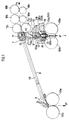
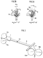
- the overlay in FIG. 1 illustrates the difference from the prior art, which is shown schematically in FIG.
- the sliver FV which has not yet been properly drawn during insertion is introduced into a long guide tube 8 via stretching rollers 68a, 68b, 69a, 69b and delivery rollers 70a, 70b, which ends in a ribbon funnel 9.
- the band funnel 9 deflects the fiber band FB approximately 90 ° into the clamping gap of the calender with its calender discs 100a, 100b.
- the calendered fiber sliver KF emerges vertically downwards from the calender and is stored in a depositing device (not shown).
- This sliver guide is also illustrated in Figure 2 with the same reference numerals.
- An embodiment of the invention shortens the sliver path and eliminates the sliver tube 8.
- An additional deflection roller 71 is added, the one Deflection of about 60 ° causes the nonwoven conveying direction FV and introduces the fiber sliver into one of several functional elements - forming the sliver channel (guide channel).
- the first element is the fleece funnel 50 (also referred to as a nozzle).
- the fleece funnel represents a nozzle with a substantially rectangular opening.
- the fleece funnel has a ramp surface 50b and a funnel section 50a arranged directly thereon, in which the broadly arriving fiber sliver (fiber fleece) is rolled, folded over and introduced into a first channel section.
- the channel section is formed by an insert 40 which is inserted at the rear of the funnel section 50a of the fleece funnel 50 and fastened with a screw. It can be adjusted.
- the fleece funnel 50 (with inner insert) can be tilted such that the ramp surface 50b can be pivoted in the transport direction of the fiber fleece (corresponds to the conveying direction) and the funnel section 50a can be pivoted next to it.
- an articulated surface 41a, 41b which, in the angular position ⁇ B , which is shown in FIG. 1 or FIG. 2b , enables the guide channel to be sealed off from the subsequent band funnel 30.
- the articulated surface 41a, 41b of the front, cylindrical section of the inner insert 40 which is symmetrical to the central plane of the first insert 40, consists of two continuously curved surface sections 41a, 41b which narrow towards the rear (in the axial direction) and which engage in a corresponding bearing surface 35 on the belt funnel 30.
- 4a and 4b show this joint surface in two views at the front end of the insert 40 for the fleece funnel 50. Swiveling the fleece funnel 50 in the direction ⁇ into the other angular position ⁇ A does not release the radially airtight seal between the fleece funnel and the band funnel. Radially airtight sliver guidance is achieved both in the swung-in ( ⁇ B ) and in the swung-out ( ⁇ A ) state.
- the radial tightness of the joint surface 41a, 41b on the bearing surface 35 is adjustable.
- the upper part (above the articular surface) can be changed in the axial direction, in particular also in the radial direction, relative to the lower part.
- the fixed holder 20, in which the band funnel 30 is inserted, forms the basis for the adjustment.
- the fleece funnel 50 is designed in two parts - with an insert 40 inserted into it opposite to the fleece conveying direction of the sliver, the aforementioned relative setting can be carried out on a handle 51.
- the fiber sliver is conveyed through the fleece funnel 50, the inner insert 40 and the belt funnel 30 into the guide channel up to the clamping gap 100c, for which purpose the fleece funnel 50 is swung out.
- the fiber fleece part F1 which is narrowed by hand according to FIG. 3 and held in the funnel mouth 50a, is sucked in via injector holes 34a, 34b, 64a, 64b on the belt funnel.
- a short suction flow in the time of 500 msec is sufficient to convey the narrowed nonwoven part F1 up to the clamping gap 100c with the least amount of pressure, since the joint surface 35 and the bearing surfaces 41a, 41b of the inner insert 40 are radially airtight. Mechanical insertion aids are not required.
- a short angular momentum of duration T 2 is applied to the calender disks. It can switch itself on after a predetermined suction time T 1 , can be superimposed on it or can be initiated separately manually.
- the shape of the band funnel 30 can be clearly seen in FIGS. 5a, 5b and 5c , where the direction and arrangement of the injector bores 34a, 34b in the band funnel are also shown enlarged. They open into a cylindrical channel 31, which forms the front end of the sliver channel.
- the cylindrical section 31 widens via a conical section 32a to the diameter of the channel 32, which is predetermined by the inner insert 40.
- the bearing surface 35 is provided, which corresponds to the articulation surface 41a, 41b in its curvature.
- the inclined injector bores 34a, 34b can run at an angle of approximately 45 ° with respect to the axis 200b of the band funnel insert 30. They are advantageously offset in parallel. This makes it possible to center the sliver in the sliver channel. Furthermore, the sliver receives a twist there. This gives the sliver strength.
- the parallel offset injector bores 34a, 34b can be seen in FIG. 5d. They open above a cylindrical section 33 of the insert 30 in an annular channel 36 that is open to the outside.
- a band funnel holder 60 according to FIGS. 6a, 6b, 6c has in the upper approximately cylindrical section 67 a central, approximately cylindrical opening 62 into which the band funnel insert 30 is inserted.
- an annular channel 63 which can be fed with compressed air from two or more cylindrical bores 64a, 64b, extends inwardly in the cylindrical opening.
- the compressed air introduced from the outside is introduced into the aforementioned inclined injector bores 34a, 34b when the ribbon funnel insert 30 is inserted, in order to open into the cylindrical section 31 of the fiber ribbon channel, which lies close to the clamping gap 100c.
- FIGS. 6a and 6b illustrate the cylindrical beak 61 of the band funnel holder 60, which adjoins a conical section 68 which forms the transition between the upper cylindrical end 67 and the beak 61. It has a length L and a diameter, shown in the cross section of FIG. 6b as width b.
- the beak 61 is arranged in a fixed manner and has two halves, since - as can be seen in FIG. 6c - it is slit on the side.
- a segment of the rotating calender disks 100a, 100b engages in the two slots mentioned. This can also be clearly seen in FIG. 1 in the right half.
- the clamping gap which according to FIGS.
- the integrally molded beak halves 61a, 61b which are formed by the aforementioned slits 61c, 61d in the cylindrical beak 61, guide the guide air, which previously passed through the injector bores 64a, 64b in the annular channel 63 and from there over the Injector bores 34a, 34b of the band funnel 30, which run obliquely to the axis 200b, were introduced into the sliver channel. With the beaks it is avoided that the guide air escapes in front of the gap 100c, 100d, rather it is guided beyond the gap to behind the clamping gap.
- a first narrow channel section 65a on one side of the calender disks or a second narrow channel section 65b on the other side of the calender disks, which have an approximately semicircular cross-sectional shape, serves to guide this air.
- the respective channel is very narrow compared to the thickness d or width b of the beak 61 or its inner wall, which is directly adjacent to the side surface of the calender disk.
- the width b of the beak and the overlap d of the inside of the beak half are opposite the calender disc a sealing effect, which is formed in a contactless manner due to significant to considerable lateral flow resistance with respect to the axial side air channels 65a, 65b.
- the sliver is also immediately threaded through the calender nip and the calender disk 100b can then be delivered in order to have reached the operating position with the sliver threaded.
- the sealing surface part of the cover d
- the sealing surface is large enough in relation to the air resistance of the now enlarged passage channel, consisting of the channel segments 65a, 65b and the open calender gap 100d, in order to prevent a radial escape of guide air.
- 4 bar can be mentioned as an example of an air pressure to be used, which is matched to a duct diameter 31 of approximately 3.8 mm in the band funnel 30 and approximately 8 mm in the duct 45 of the insert 40 of the fleece funnel 50.
- a compressed air pulse of approx. 500 milliseconds (ms) duration is sufficient to safely insert the front part F1 of the nonwoven fabric up to the clamping gap 100c.
- the length H1 of the manually narrowed fiber fleece is matched to the distance from the fleece funnel 50 to the clamping gap 100c and thus the length of the airtight fiber sliver channel.
- the mentioned inwardly pointing ring channel 63 can also be formed on the insert 30 as an outwardly pointing channel 36, for example by a circumferential notch. Both channels 63, 36 can also be provided in order to jointly form an annular channel when the funnel 30 and holder 60 are connected.
- the band funnel holder 60 has an intermediate truncated cone 68 between its upper cylindrical section 62 and its beak section 61. With it and with the cylindrical section 68, it can be used in a carrier 20 which is positioned just above the calender disks 100a, 100b in such a way that the beak section 61 of the holder 60 engages over the calender disks and the clamping gap.
- the fleece nozzle 50 is also pivotably held on the carrier 20 by means of bearing tabs 52a, 52b which create a distance. All parts of the nozzle system are interchangeable, but still fixed exactly in position.
- the possibility of exchanging all parts of the nozzle system opens up the possibility of modular construction of the sliver guide device between the exit the delivery rollers and the storage of the calendered sliver. Adjustment work or adjustment work with adjustment to certain calender disk widths or for certain fiber types or processing specifications are no longer necessary. If processing specifications are made, there are modular nozzles that are connected to one another via their respective inserts. The inserts fit into each of the modular nozzles and establish the connection between the individual technology parts. The interchangeability also enables a change as a result of a lot change.
- One insert 40 was described with reference to FIGS . 4a, 4b . It is inserted into the fleece funnel 50 against the transport direction of the sliver. Its front end is the hinge surface 41b, 41b, which is attached to a cylindrical tube section 41. It has a continuous curvature which is oriented backwards on both sides of the central plane of the insert 40, the width of which decreases symmetrically on both sides. The width is reduced transversely to the axial direction of the guide channel 200a. The joint surface at the front end has the greatest width.
- the pipe section 41 on which the articulated surface 41a, 41b is attached, is arranged in one piece on a cone section 43 which merges into a cylindrical region 45 which has a slightly larger diameter than the likewise cylindrical insertion section 42.
- the cylindrical section 45 can be a Act as a stop when the insertion section 42 is inserted into the fleece funnel 50 from the rear (against the direction of transport of the sliver).
- the inner insert 30 for the band funnel holder 60 is shown in FIGS. 5a to 5d . It has the complementary receiving bearing surface 35 to the joint surfaces 41a, 41b of the insert described above. The bearing surfaces 35 also narrow in the direction of the axis 200a of the conveying direction. The bearing surface 35 has the smallest width at the end inlet end of the insert 30.
- the outer dimensions of the insert 30 are designed so that it can be inserted into the band funnel holder 60.
- the holder 60 is formed in one piece and explained in more detail in three views with reference to Figures 6a to 6c . It is significantly larger than the actual band funnel, which is formed by the insert 30 in this exemplary embodiment.
- the holder 60 is fixedly fixed in relation to the calender disks, it carries injector nozzles 64a, 64b in order to introduce air in the guide direction into the sliver guide system.
- the air supply is made easier by the fixed attachment of the holder, since it does not have to be pivoted as well.
- Figures 9a, 9b show the fixed holder 20, into which the band funnel holder 60 is inserted into a conical insertion section, so that it is fixed exactly in relation to the calender disks.
- the beak halves 61a, 61b reaching over the calender disks are each designed semi-circular in the exemplary embodiment. They are integrally formed on a cone 68, which also merges in one piece into the cylindrical section 67 of the holder 60.
- a cylindrical opening 62 is provided in the cylindrical section 67, into which any belt funnel insert 30 can be inserted.
- the outer dimension of each band funnel 30 to be used is matched to the inner dimension of the holder 60. Even if there are different technology requirements that dictate the band hopper in a form of channel 32a, 32, 31, the same band hopper holder 60 can be used.
- the flow openings 64a, 64b are provided, with which air is introduced near the calender disks in order to guide them with the half-round beaks 61 in such a way that they at least not in front of the calender gap 100c (or 100d according to FIG. 7b ) can escape.
- widenings 65a, 65b are provided, which lead past the calender gap 100c according to FIG. 7 .
- Their dimension in relation to the width of the calender disks or in relation to the width b of the half-round beaks can be clearly seen from FIG. 7a or 7b .
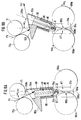
- FIGS. 8a and 8b show the design of a guide section which is essentially made in one piece and contains both the fleece nozzle 50 and the belt funnel 30.
- the band funnel 30 is inserted directly into the fleece nozzle 50 and is additionally fixed in position by a tube holder 80.
- the front end of the band funnel 30 is supported in comparable bearing shells and rounded surfaces, as described for the fleece funnel insert 40 with reference to FIGS. 4b and 5c .
- FIGS. 8a and 8b The radial seal is also achieved in FIGS. 8a and 8b , where a residual guide section 61 'is fixedly arranged with respect to the calender disks, for example on the holder 20 according to FIG . 9a .
- the remaining guide section 61 ' corresponds to the beak region L of the band funnel holder 60 from FIG . 6a .
- the air is introduced into the combined fleece funnel / belt funnel at the front end thereof via inclined injector bores 34a, 34b, with a pivoting movement causing a slight pivoting of the air introduction region, which, however, is only slight due to its proximity to the pivot point K.
- FIGS. 8a and 8b are designated ⁇ 1 and ⁇ 2 , they correspond to the pivot positions ⁇ A and ⁇ B , but can be dimensioned slightly differently, since the pivotable part in FIGS. 8a and 8b is larger or longer than in Figures 3a and 3b .
- the sliver guide sections are defined by different bores and corresponding conical transition sections.
- An exchange of the insert 40 is at the same time an exchange of the band funnel 30.
- Readjustments or adjustment work can be omitted due to the one-piece training.
- the annular holder 80 does not lie completely flush with the combined fleece funnel / belt funnel, but rather leaves an annular space 81 between the inside of the funnel and the outer diameter of the largely cylindrical combination funnel 30/40.
- the annular space 81 guides the compressed air used to guide the fibers, whereby it is sealed at the end by flush (annular) contact with the combination nozzle - below the injector bores 34a, 34b.
- a suitable height which can be selected depending on the application, is an outward main air supply which opens into the annular space, is able to build up compressed air there and feeds the injector bores 34a, 34b.
- the injector bores are clearly inclined with respect to the axis 200b; they open out just in front of the radially airtight joint K, on which a radially airtight mounting takes place in both positions of FIG. 8 and FIG. 8b .
- the angles ⁇ 1 and ⁇ 2 are each slightly reduced compared to the example in FIGS. 2a and 2b , but in the same specified range as in FIGS. 2.
- the exact angle in this exemplary embodiment is approximately 5 ° for ⁇ 2 and approximately for ⁇ 1 25 ° ( ⁇ 10%), while in Figure 2a an angle of ⁇ A of approximately 30 ° and in Figure 2b an angle of approximately 7 ° ( ⁇ 10%) worked reliably in the experiment.
- the plateau region 50b in FIGS. 8a and 8b is accordingly somewhat adapted to the angle of the ramp region 50b in FIGS. 2a and 7b. It depends on the angles ⁇ in the respective swivel end positions; where the pivot position ⁇ 1 and ⁇ A specifies such an angle of the ramp that the conveying direction of the nonwoven fabric FV is clearly directed transversely from the exit region of the route. It is most advantageous if the transverse direction FV 'is one receives a slight component downwards, i.e. it is inclined slightly downwards relative to the horizontal.
- the ramp area either has a slight slope of 1 ° to 2 ° with respect to the funnel area or it is slightly conical.
- FIGS. 8a and 8b two different sliver channel dimensions are shown in FIGS. 8a and 8b , a narrow and a wide one, each with a conical shoulder to the narrowest cylindrical section of the sliver channel.
- FIGS Figures 4 and 5 show a side view and a top view of the fleece funnel 50 with its ramp area 50b and its funnel area 50a according to FIG. 3.
- the pivoting sleeve V lies transversely to the guide axis 200a, 200b and runs through the airtight joint 41a, 41b and 35, as in FIGS Figures 4 and 5 explained.
- the pivot axis V runs through the bearings 50c, which are formed by lateral retaining tabs 52a, 52b and pins, on which pivot receptacles that are at least half open on the front can be placed.
- the fleece funnel 50 can thus be removed and tilted, while at the same time sealing the internally formed guide channel 200a, 200b in an airtight manner.
Landscapes
- Engineering & Computer Science (AREA)
- Mechanical Engineering (AREA)
- Textile Engineering (AREA)
- Spinning Or Twisting Of Yarns (AREA)
Priority Applications (1)
| Application Number | Priority Date | Filing Date | Title |
|---|---|---|---|
| EP96102887A EP0736618B1 (fr) | 1995-04-07 | 1996-02-27 | Dispositif de guidage pour introduire un ruban de fibres dans la ligne de pincement des disques d'une calandre d'une machine de textile utilisant des rubans de fibres et un procédé d'introduction |
Applications Claiming Priority (9)
| Application Number | Priority Date | Filing Date | Title |
|---|---|---|---|
| DE29506107U | 1995-04-07 | ||
| DE29506107 | 1995-04-07 | ||
| DE29511919U | 1995-07-24 | ||
| DE29511919 | 1995-07-24 | ||
| EP95114975A EP0736617B1 (fr) | 1995-04-07 | 1995-09-22 | Transport pneumatique de mèche de fibres dans une calandre |
| EP95114975 | 1995-09-22 | ||
| DE19535297A DE19535297A1 (de) | 1995-04-07 | 1995-09-22 | Kompakte Vliesführung ohne Führungsrohr und Austauschdüsen dafür |
| DE19535297 | 1995-09-22 | ||
| EP96102887A EP0736618B1 (fr) | 1995-04-07 | 1996-02-27 | Dispositif de guidage pour introduire un ruban de fibres dans la ligne de pincement des disques d'une calandre d'une machine de textile utilisant des rubans de fibres et un procédé d'introduction |
Publications (2)
| Publication Number | Publication Date |
|---|---|
| EP0736618A1 true EP0736618A1 (fr) | 1996-10-09 |
| EP0736618B1 EP0736618B1 (fr) | 1999-01-27 |
Family
ID=27512475
Family Applications (1)
| Application Number | Title | Priority Date | Filing Date |
|---|---|---|---|
| EP96102887A Expired - Lifetime EP0736618B1 (fr) | 1995-04-07 | 1996-02-27 | Dispositif de guidage pour introduire un ruban de fibres dans la ligne de pincement des disques d'une calandre d'une machine de textile utilisant des rubans de fibres et un procédé d'introduction |
Country Status (1)
| Country | Link |
|---|---|
| EP (1) | EP0736618B1 (fr) |
Cited By (2)
| Publication number | Priority date | Publication date | Assignee | Title |
|---|---|---|---|---|
| EP0913510A1 (fr) * | 1997-10-30 | 1999-05-06 | Zellweger Luwa Ag | Dispositif pour enfiler un produit intermédiaire textile allongé |
| CN106592029A (zh) * | 2017-01-19 | 2017-04-26 | 江苏凯宫机械股份有限公司 | 智能精梳机台面输出喇叭口集束装置 |
Families Citing this family (1)
| Publication number | Priority date | Publication date | Assignee | Title |
|---|---|---|---|---|
| PL3470214T3 (pl) | 2017-10-10 | 2021-11-15 | Groz-Beckert Kg | Urządzenie i sposób wytwarzania zawierającej wiele wiązek włókien części nośnej |
Citations (2)
| Publication number | Priority date | Publication date | Assignee | Title |
|---|---|---|---|---|
| FR2597119A1 (fr) * | 1986-04-10 | 1987-10-16 | Zinser Textilmaschinen Gmbh | Conduit de guidage de ruban entre cylindres de sortie et cylindres de calandre dans une machine de preparation de filature |
| EP0325294A2 (fr) * | 1988-01-21 | 1989-07-26 | Zinser Textilmaschinen GmbH | Conduit de guidage d'un ruban |
-
1996
- 1996-02-27 EP EP96102887A patent/EP0736618B1/fr not_active Expired - Lifetime
Patent Citations (2)
| Publication number | Priority date | Publication date | Assignee | Title |
|---|---|---|---|---|
| FR2597119A1 (fr) * | 1986-04-10 | 1987-10-16 | Zinser Textilmaschinen Gmbh | Conduit de guidage de ruban entre cylindres de sortie et cylindres de calandre dans une machine de preparation de filature |
| EP0325294A2 (fr) * | 1988-01-21 | 1989-07-26 | Zinser Textilmaschinen GmbH | Conduit de guidage d'un ruban |
Cited By (3)
| Publication number | Priority date | Publication date | Assignee | Title |
|---|---|---|---|---|
| EP0913510A1 (fr) * | 1997-10-30 | 1999-05-06 | Zellweger Luwa Ag | Dispositif pour enfiler un produit intermédiaire textile allongé |
| US6032335A (en) * | 1997-10-30 | 2000-03-07 | Zellweger Luwa Ag | Apparatus for drawing a fibrous strand into an element of a textile machine |
| CN106592029A (zh) * | 2017-01-19 | 2017-04-26 | 江苏凯宫机械股份有限公司 | 智能精梳机台面输出喇叭口集束装置 |
Also Published As
| Publication number | Publication date |
|---|---|
| EP0736618B1 (fr) | 1999-01-27 |
Similar Documents
| Publication | Publication Date | Title |
|---|---|---|
| EP0407732B1 (fr) | Métier à filer à bout libre | |
| DE102007006674A1 (de) | Luftspinnvorrichtung | |
| DE3801688C2 (de) | Bandführungskanal | |
| DE3638110C2 (de) | Vorrichtung zum pneumatischen Falschdrallspinnen | |
| EP0736619B1 (fr) | Méthode et dispositif pour insérer du ruban devant la fente de pincement des disques de calandre | |
| EP0178466B1 (fr) | Procédé et dispositif pour la fabrication d'un fil | |
| EP1217109A2 (fr) | Dispositif de filage | |
| DE3639031A1 (de) | Vorrichtung zur herstellung eines gesponnenen fadens | |
| CH694332A5 (de) | Verfahren und Vorrichtung zur Herstellung eines Garnes mit ringgarnähnlichem Charakter. | |
| EP2006425B1 (fr) | Dispositif sur une machine de préparation de filature | |
| EP0736620B1 (fr) | Dispositif de guidage pour ruban de fibres pour une machine de textile utilisant des rubans de fibres et procédé pour son opération | |
| EP0736618B1 (fr) | Dispositif de guidage pour introduire un ruban de fibres dans la ligne de pincement des disques d'une calandre d'une machine de textile utilisant des rubans de fibres et un procédé d'introduction | |
| DE102017130224A1 (de) | Streckwerk und Verdichtungsvorrichtung für eine Spinnereimaschine | |
| DE19945319B4 (de) | Vliestrichter | |
| DE19535297A1 (de) | Kompakte Vliesführung ohne Führungsrohr und Austauschdüsen dafür | |
| EP0736617B1 (fr) | Transport pneumatique de mèche de fibres dans une calandre | |
| DE19535300B4 (de) | Luftgestütztes Einführen von Faserband vor den Klemmspalt | |
| DE10154127A1 (de) | Vorrichtung an einer Spinnmaschine zum Verdichten eines Faserverbandes | |
| DE10150565B4 (de) | Verfahren und Vorrichtung zur Vorbereitung eines abgelängten Fadenendes für das Wiederanspinnen einer Offenend-Spinnvorrichtung | |
| DE3205938A1 (de) | Rundstrick- oder rundwirkmaschine zur herstellung von florware mit eingekaemmten fasern | |
| DE3416456C2 (de) | Verfahren und Vorrichtung zur Inbetriebnahme einer Friktionsspinnmaschine | |
| DE19640855A1 (de) | Vorrichtung zum Zusammenfassen eines Vlieses zu einem Faserband am Ausgang von Streckwerken | |
| EP0205840B1 (fr) | Procédé et dispositif de filature par friction par fibres libérées | |
| EP1654407B1 (fr) | Dispositif de guidage de non-tisse pour machine textile et machine textile | |
| DE19535347A1 (de) | Schwenkbarer Vliestrichter für Vliesführung ohne Führungsrohr |
Legal Events
| Date | Code | Title | Description |
|---|---|---|---|
| PUAI | Public reference made under article 153(3) epc to a published international application that has entered the european phase |
Free format text: ORIGINAL CODE: 0009012 |
|
| 17P | Request for examination filed |
Effective date: 19960227 |
|
| AK | Designated contracting states |
Kind code of ref document: A1 Designated state(s): CH DE IT LI |
|
| 17Q | First examination report despatched |
Effective date: 19961113 |
|
| GRAG | Despatch of communication of intention to grant |
Free format text: ORIGINAL CODE: EPIDOS AGRA |
|
| GRAG | Despatch of communication of intention to grant |
Free format text: ORIGINAL CODE: EPIDOS AGRA |
|
| GRAG | Despatch of communication of intention to grant |
Free format text: ORIGINAL CODE: EPIDOS AGRA |
|
| GRAH | Despatch of communication of intention to grant a patent |
Free format text: ORIGINAL CODE: EPIDOS IGRA |
|
| GRAH | Despatch of communication of intention to grant a patent |
Free format text: ORIGINAL CODE: EPIDOS IGRA |
|
| GRAA | (expected) grant |
Free format text: ORIGINAL CODE: 0009210 |
|
| AK | Designated contracting states |
Kind code of ref document: B1 Designated state(s): CH DE IT LI |
|
| REG | Reference to a national code |
Ref country code: CH Ref legal event code: EP |
|
| REF | Corresponds to: |
Ref document number: 59601205 Country of ref document: DE Date of ref document: 19990311 |
|
| REG | Reference to a national code |
Ref country code: CH Ref legal event code: NV Representative=s name: ISLER & PEDRAZZINI AG |
|
| ITF | It: translation for a ep patent filed | ||
| PLBE | No opposition filed within time limit |
Free format text: ORIGINAL CODE: 0009261 |
|
| STAA | Information on the status of an ep patent application or granted ep patent |
Free format text: STATUS: NO OPPOSITION FILED WITHIN TIME LIMIT |
|
| 26N | No opposition filed | ||
| PGFP | Annual fee paid to national office [announced via postgrant information from national office to epo] |
Ref country code: CH Payment date: 20040225 Year of fee payment: 9 |
|
| PG25 | Lapsed in a contracting state [announced via postgrant information from national office to epo] |
Ref country code: LI Free format text: LAPSE BECAUSE OF NON-PAYMENT OF DUE FEES Effective date: 20050228 Ref country code: CH Free format text: LAPSE BECAUSE OF NON-PAYMENT OF DUE FEES Effective date: 20050228 |
|
| REG | Reference to a national code |
Ref country code: CH Ref legal event code: PL |
|
| PGFP | Annual fee paid to national office [announced via postgrant information from national office to epo] |
Ref country code: IT Payment date: 20060228 Year of fee payment: 11 |
|
| PG25 | Lapsed in a contracting state [announced via postgrant information from national office to epo] |
Ref country code: IT Free format text: LAPSE BECAUSE OF NON-PAYMENT OF DUE FEES Effective date: 20070227 |
|
| PGFP | Annual fee paid to national office [announced via postgrant information from national office to epo] |
Ref country code: DE Payment date: 20130408 Year of fee payment: 18 |
|
| REG | Reference to a national code |
Ref country code: DE Ref legal event code: R119 Ref document number: 59601205 Country of ref document: DE |
|
| REG | Reference to a national code |
Ref country code: DE Ref legal event code: R119 Ref document number: 59601205 Country of ref document: DE Effective date: 20140902 |
|
| PG25 | Lapsed in a contracting state [announced via postgrant information from national office to epo] |
Ref country code: DE Free format text: LAPSE BECAUSE OF NON-PAYMENT OF DUE FEES Effective date: 20140902 |