EP0736408A2 - Wählhebelanordnung für automatische Getriebe für Kraftfahrzeuge mit manueller Schaltmöglichkeit - Google Patents
Wählhebelanordnung für automatische Getriebe für Kraftfahrzeuge mit manueller Schaltmöglichkeit Download PDFInfo
- Publication number
- EP0736408A2 EP0736408A2 EP96104275A EP96104275A EP0736408A2 EP 0736408 A2 EP0736408 A2 EP 0736408A2 EP 96104275 A EP96104275 A EP 96104275A EP 96104275 A EP96104275 A EP 96104275A EP 0736408 A2 EP0736408 A2 EP 0736408A2
- Authority
- EP
- European Patent Office
- Prior art keywords
- selector lever
- locking
- spring
- loaded
- neutral position
- Prior art date
- Legal status (The legal status is an assumption and is not a legal conclusion. Google has not performed a legal analysis and makes no representation as to the accuracy of the status listed.)
- Granted
Links
Images


Classifications
-
- F—MECHANICAL ENGINEERING; LIGHTING; HEATING; WEAPONS; BLASTING
- F16—ENGINEERING ELEMENTS AND UNITS; GENERAL MEASURES FOR PRODUCING AND MAINTAINING EFFECTIVE FUNCTIONING OF MACHINES OR INSTALLATIONS; THERMAL INSULATION IN GENERAL
- F16H—GEARING
- F16H59/00—Control inputs to control units of change-speed- or reversing-gearings for conveying rotary motion
- F16H59/02—Selector apparatus
- F16H59/0204—Selector apparatus for automatic transmissions with means for range selection and manual shifting, e.g. range selector with tiptronic
-
- F—MECHANICAL ENGINEERING; LIGHTING; HEATING; WEAPONS; BLASTING
- F16—ENGINEERING ELEMENTS AND UNITS; GENERAL MEASURES FOR PRODUCING AND MAINTAINING EFFECTIVE FUNCTIONING OF MACHINES OR INSTALLATIONS; THERMAL INSULATION IN GENERAL
- F16H—GEARING
- F16H59/00—Control inputs to control units of change-speed- or reversing-gearings for conveying rotary motion
- F16H2059/006—Overriding automatic control
-
- F—MECHANICAL ENGINEERING; LIGHTING; HEATING; WEAPONS; BLASTING
- F16—ENGINEERING ELEMENTS AND UNITS; GENERAL MEASURES FOR PRODUCING AND MAINTAINING EFFECTIVE FUNCTIONING OF MACHINES OR INSTALLATIONS; THERMAL INSULATION IN GENERAL
- F16H—GEARING
- F16H59/00—Control inputs to control units of change-speed- or reversing-gearings for conveying rotary motion
- F16H59/02—Selector apparatus
- F16H2059/0239—Up- and down-shift or range or mode selection by repeated movement
-
- F—MECHANICAL ENGINEERING; LIGHTING; HEATING; WEAPONS; BLASTING
- F16—ENGINEERING ELEMENTS AND UNITS; GENERAL MEASURES FOR PRODUCING AND MAINTAINING EFFECTIVE FUNCTIONING OF MACHINES OR INSTALLATIONS; THERMAL INSULATION IN GENERAL
- F16H—GEARING
- F16H59/00—Control inputs to control units of change-speed- or reversing-gearings for conveying rotary motion
- F16H59/02—Selector apparatus
- F16H59/0278—Constructional features of the selector lever, e.g. grip parts, mounting or manufacturing
- F16H2059/0282—Lever handles with lock mechanisms, e.g. for allowing selection of reverse gear or releasing lever from park position
-
- F—MECHANICAL ENGINEERING; LIGHTING; HEATING; WEAPONS; BLASTING
- F16—ENGINEERING ELEMENTS AND UNITS; GENERAL MEASURES FOR PRODUCING AND MAINTAINING EFFECTIVE FUNCTIONING OF MACHINES OR INSTALLATIONS; THERMAL INSULATION IN GENERAL
- F16H—GEARING
- F16H59/00—Control inputs to control units of change-speed- or reversing-gearings for conveying rotary motion
- F16H59/02—Selector apparatus
- F16H59/08—Range selector apparatus
- F16H59/10—Range selector apparatus comprising levers
-
- F—MECHANICAL ENGINEERING; LIGHTING; HEATING; WEAPONS; BLASTING
- F16—ENGINEERING ELEMENTS AND UNITS; GENERAL MEASURES FOR PRODUCING AND MAINTAINING EFFECTIVE FUNCTIONING OF MACHINES OR INSTALLATIONS; THERMAL INSULATION IN GENERAL
- F16H—GEARING
- F16H61/00—Control functions within control units of change-speed- or reversing-gearings for conveying rotary motion ; Control of exclusively fluid gearing, friction gearing, gearings with endless flexible members or other particular types of gearing
- F16H61/24—Providing feel, e.g. to enable selection
-
- Y—GENERAL TAGGING OF NEW TECHNOLOGICAL DEVELOPMENTS; GENERAL TAGGING OF CROSS-SECTIONAL TECHNOLOGIES SPANNING OVER SEVERAL SECTIONS OF THE IPC; TECHNICAL SUBJECTS COVERED BY FORMER USPC CROSS-REFERENCE ART COLLECTIONS [XRACs] AND DIGESTS
- Y10—TECHNICAL SUBJECTS COVERED BY FORMER USPC
- Y10T—TECHNICAL SUBJECTS COVERED BY FORMER US CLASSIFICATION
- Y10T74/00—Machine element or mechanism
- Y10T74/19—Gearing
- Y10T74/19219—Interchangeably locked
- Y10T74/19251—Control mechanism
-
- Y—GENERAL TAGGING OF NEW TECHNOLOGICAL DEVELOPMENTS; GENERAL TAGGING OF CROSS-SECTIONAL TECHNOLOGIES SPANNING OVER SEVERAL SECTIONS OF THE IPC; TECHNICAL SUBJECTS COVERED BY FORMER USPC CROSS-REFERENCE ART COLLECTIONS [XRACs] AND DIGESTS
- Y10—TECHNICAL SUBJECTS COVERED BY FORMER USPC
- Y10T—TECHNICAL SUBJECTS COVERED BY FORMER US CLASSIFICATION
- Y10T74/00—Machine element or mechanism
- Y10T74/20—Control lever and linkage systems
- Y10T74/20012—Multiple controlled elements
- Y10T74/20018—Transmission control
- Y10T74/20067—Control convertible between automatic and manual operation
-
- Y—GENERAL TAGGING OF NEW TECHNOLOGICAL DEVELOPMENTS; GENERAL TAGGING OF CROSS-SECTIONAL TECHNOLOGIES SPANNING OVER SEVERAL SECTIONS OF THE IPC; TECHNICAL SUBJECTS COVERED BY FORMER USPC CROSS-REFERENCE ART COLLECTIONS [XRACs] AND DIGESTS
- Y10—TECHNICAL SUBJECTS COVERED BY FORMER USPC
- Y10T—TECHNICAL SUBJECTS COVERED BY FORMER US CLASSIFICATION
- Y10T74/00—Machine element or mechanism
- Y10T74/20—Control lever and linkage systems
- Y10T74/20012—Multiple controlled elements
- Y10T74/20018—Transmission control
- Y10T74/20085—Restriction of shift, gear selection, or gear engagement
- Y10T74/20098—Separate actuator to disengage restrictor
-
- Y—GENERAL TAGGING OF NEW TECHNOLOGICAL DEVELOPMENTS; GENERAL TAGGING OF CROSS-SECTIONAL TECHNOLOGIES SPANNING OVER SEVERAL SECTIONS OF THE IPC; TECHNICAL SUBJECTS COVERED BY FORMER USPC CROSS-REFERENCE ART COLLECTIONS [XRACs] AND DIGESTS
- Y10—TECHNICAL SUBJECTS COVERED BY FORMER USPC
- Y10T—TECHNICAL SUBJECTS COVERED BY FORMER US CLASSIFICATION
- Y10T74/00—Machine element or mechanism
- Y10T74/20—Control lever and linkage systems
- Y10T74/20012—Multiple controlled elements
- Y10T74/20018—Transmission control
- Y10T74/20085—Restriction of shift, gear selection, or gear engagement
- Y10T74/20104—Shift element interlock
- Y10T74/2011—Shift element interlock with detent, recess, notch, or groove
-
- Y—GENERAL TAGGING OF NEW TECHNOLOGICAL DEVELOPMENTS; GENERAL TAGGING OF CROSS-SECTIONAL TECHNOLOGIES SPANNING OVER SEVERAL SECTIONS OF THE IPC; TECHNICAL SUBJECTS COVERED BY FORMER USPC CROSS-REFERENCE ART COLLECTIONS [XRACs] AND DIGESTS
- Y10—TECHNICAL SUBJECTS COVERED BY FORMER USPC
- Y10T—TECHNICAL SUBJECTS COVERED BY FORMER US CLASSIFICATION
- Y10T74/00—Machine element or mechanism
- Y10T74/20—Control lever and linkage systems
- Y10T74/20576—Elements
- Y10T74/20636—Detents
- Y10T74/20672—Lever engaging rack
- Y10T74/20696—Finger lever release
- Y10T74/20702—Slidable
Definitions
- the invention relates to a selector lever arrangement for automatic transmissions of motor vehicles with a manual switching option, the type explained in the preamble of claim 1.
- the invention is based on a selector lever for automatic transmissions of motor vehicles, as shown in DE-PS 43 05 015 and in a shift gate only in one plane forwards or backwards into the known positions P, R, N and D. and 2 and 1 is movable.
- a shift lever for an automatically switchable manual transmission of motor vehicles which can only be moved forwards or backwards in one plane and which, depending on two switches arranged on the handle of the selector lever, can be moved forwards or backwards shifting the shift lever backward, an upshift or a downshift can be initiated, it being possible here to switch between two gear stages each, which are assigned to a shift range which is predetermined by the position of the switches on the selector lever.
- the known shift lever thus has the disadvantage that it is only possible to change between two gear stages, then only one of the switches on the shift lever must be actuated in order to be able to then switch between the next two gear stages.
- the desired simplification of a gearshift actuation is hardly achieved, since the driver of the motor vehicle also actuates the gearshift lever still have to operate different switches.
- a selector lever for automatic transmissions of motor vehicles is known, with a manual switching option, for example of the type explained in the preamble of patent claim 1.
- the selector lever in order to take advantage of the manual switching option, the selector lever must be moved laterally out of one plane to actuate the known positions P, R, N and D, 3, 2 and 1, and then in a parallel shifting gate into a forward position "+" actuating an upshifting switch and moving into a rear position "-" actuating a downshifting switch, the selector lever being returned spring-loaded from these two positions to its central position or neutral position.
- the object of the invention is to provide a selector lever for automatic transmissions of motor vehicles, with a manual shift option, of the type explained in the preamble of claim 1, which, with the least possible manufacturing and assembly effort, enables extremely simple and appropriate exercise of the manual shift option by Provides driver.
- a selector lever arrangement 1 for an automatic transmission of a motor vehicle essentially consists of a selector lever housing 2 which can be fastened to the vehicle floor (not shown) and which is produced from a correspondingly high-quality plastic material by injection molding.
- the dome-like selector lever housing 2 has approximately vertical side walls 3, 4, 5 and 6, of which the two side side walls 3 and 5 have bearing openings 7 and 8 for a horizontal transverse axis 9.
- a selector lever 10 has a handle 11 at the top with a control button 12 and is connected at the bottom to a bearing component 13 by means of which it is pivotably mounted on the horizontal transverse axis 9.
- the dome-like selector lever housing 2 is covered at the top by a parallel-walled latching component 14, in the side walls 15 and 16 of which latching links 17 and 18 are arranged, which cooperate with a latching device in the form of a horizontal latching bolt 19, which is connected via a corresponding connection (only indicated by broken lines) can be influenced by the control button 12.
- the selector lever arrangement is covered towards the vehicle interior by a cover panel 20 in a stylistically pleasing manner.
- the bearing component 13 being able to have arms which extend both above the horizontal transverse axis 9 and below and which can be used to connect the Bowden cable connections to the automatic transmission, depending on whether the Bowden cable arrangement is arranged above or below the horizontal transverse axis 9, no or a redirection of the direction of selection occurs.
- the bearing component 13 is connected to a connection arrangement 21, which consists of a first toothed segment 22 formed on the bearing component 13, which is in engagement with a second toothed segment 23, which is arranged in a lower horizontal transverse axis 24, which in parts of the downward extending side walls 3 and 5 of the selector lever housing 2 is pivotally received.
- a lever arm 25 is arranged in a rotationally fixed manner, at whose lower end 26 the Bowden cable connection 27 is articulated to the automatic transmission.
- the selector lever arrangement described so far corresponds to the selector lever arrangement which represents the starting point of the present invention and which is described in DE-PS 43 05 015.
- the selector lever arrangement according to the invention has changes in the latching link and in the latching arrangement, which are explained in more detail below in connection with the enlarged illustration in FIG. 3.
- the latching links 17 and 18 formed in the parallel-walled latching component 14, in the side walls 15 and 16 thereof, which cooperate with a horizontal latching bolt 19, are designed in a special way, which will now be explained.
- the locking recesses of the locking link remain unchanged in the areas for the selector lever positions P, R, N and D a change is only made in the area of the earlier switching positions 2 and 1.
- the previous switching positions 2 and 1 could only be selected by pressing the control button 12 on the handle 11 of the selector lever 10.
- the locking cam provided for this purpose is designated 31. Following the locking cam 31, according to the invention, there is a roof-like angle section 32, starting from the apex 33 of which two bevels 34 and 35 follow.
- the spring-loaded locking pin 19 pushes into the apex position 33 of the roof-like angle section 34, 35 of the locking link 17 and 18 and thereby holds the selector lever in its further neutral position M.
- the selector lever If the selector lever is moved from its neutral position M to a forward position "+”, it actuates a limit switch 36, which is provided for triggering an upshift. If the selector lever is moved into a rear position "-”, it actuates a limit switch 37, which is provided for triggering a downshift. As soon as the manual actuation force on the selector lever stops, the spring-loaded locking pin 19 guides the selector lever back into its neutral position M as a result of the bevels 34 and 35.
- the spring force provided for actuating the locking pin 19 cannot be chosen so high for comfort reasons that a desired quick return of the selector lever to the neutral position M can take place with the desired force, therefore, according to a development of the invention, it is proposed to the cam segment 28 present on the bearing component 13 with the catches 29 and the spring catch 30, the last of the catches 38, which corresponds functionally to the roof-like angle section 33, 34 and 35 in the catch link, trained accordingly and to cooperate with a locking roller 40 reinforced by a double spring arrangement 39, which brings about the desired safe return movement of the selector lever into its neutral position M.
Landscapes
- Engineering & Computer Science (AREA)
- General Engineering & Computer Science (AREA)
- Mechanical Engineering (AREA)
- Arrangement Or Mounting Of Control Devices For Change-Speed Gearing (AREA)
- Control Of Transmission Device (AREA)
Abstract
Description
- Die Erfindung bezieht sich auf eine Wählhebelanordnung für automatische Getriebe von Kraftfahrzeugen mit einer manuellen Schaltmöglichkeit, der im Oberbegriff des Patentanspruches 1 erläuterten Art.
- Die Erfindung geht von einem Wählhebel für automatische Getriebe von Kraftfahrzeugen aus, wie er in der DE-PS 43 05 015 gezeigt ist und der in einer Schaltkulisse nur in einer Ebene nach vorn oder nach hinten in die bekannten Positionen P, R, N und D sowie 2 und 1 bewegbar ist.
- Aus der DE-PS 33 31 223 ist ein Schalthebel für ein automatisch schaltbares manuelles Getriebe von Kraftfahrzeugen bekannt, der nur in einer Ebene nach vorn oder nach hinten bewegbar ist und bei dem in Abhängigkeit von zwei am Handgriff des Wählhebels angeordneten Schaltern durch nach vorne oder nach hinten Verlagern des Schalthebels eine Aufwärtsschaltung bzw. eine Abwärtsschaltung eingeleitet werden kann, wobei hier nur zwischen jeweils zwei Gangstufen gewechselt werden kann, die einem Schaltbereich zugeordnet sind, der durch die Stellung der Schalter am Wählhebel vorgegeben wird.
- Der bekannte Schalthebel weist damit den Nachteil auf, daß jeweils nur zwischen zwei Gangstufen gewechselt werden kann, dann erst einer der Schalter am Schalthebel betätigt werden muß, um dann zwischen den nächsten beiden Gangstufen wechseln zu können. Die angestrebte Vereinfachung einer Schaltungsbetätigung wird damit wohl kaum erreicht, da der Fahrer des Kraftfahrzeuges neben der Betätigung des Schalthebels auch noch die Betätigung von unterschiedlichen Schaltern übernehmen muß.
- Aus der EP-PS 0 331 797 ist ein Wählhebel für automatische Getriebe von Kraftfahrzeugen, mit einer manuellen Schaltmöglichkeit etwa der im Oberbegriff des Patentanspruches 1 erläuterten Art bekannt. Um jedoch die manuelle Schaltmöglichkeit wahrzunehmen, muß der Wählhebel seitlich aus der einen Ebene zur Betätigung der bekannten Positionen P, R, N und D, 3, 2 und 1 herausbewegt werden, um dann in einer parallelen Schaltkulisse in eine vordere Position "+" einen eine Aufwärtsschaltung bewirkenden Schalter betätigend und in eine hintere Position "-" einen eine Abwärtsschaltung bewirkenden Schalter betätigend bewegbar ist, wobei der Wählhebel aus diesen beiden Positionen jeweils federbelastet in seine Mittelstellung oder Neutrallage zurückgeführt wird.
- Dieser bekannte Wählhebel schafft zwar eine Vereinfachung für die manuelle Schaltbetätigung, erfordert jedoch durch das seitliche Verschwenken in die zweite parallele Schaltkulisse einen erhöhten mechanischen Aufbau, der die Herstellungs- und Montagekosten erhöht.
- Die Aufgabe der Erfindung ist es, einen Wählhebel für automatische Getriebe von Kraftfahrzeuge, mit einer manuellen Schaltmöglichkeit, der im Oberbegriff des Patentanspruches 1 erläuterten Art zu schaffen, der bei möglichst geringem Herstellungs- und Montageaufwand eine äußerst einfache und sinngemäße Ausübung der manuellen Schaltmöglichkeit durch den Fahrer bereitstellt.
- Diese Aufgabe wird gelöst, indem bei einem Wählhebel für automatische Getriebe von Kraftfahrzeugen, mit einer manuellen Schaltmöglichkeit, der im Oberbegriff des Patentanspruches 1 erläuterten Art die im Kennzeichenteil des Patentanspruches 1 aufgeführten Merkmale angewendet werden.
- Dadurch, daß der Wählhebel in der Wählhebelkulisse aus der Position D nur durch Betätigen eines an sich vorhandenen Kontrollknopfes am Handgriff zum Betätigen eines federbelasteten Sperrstiftes, der mit der Kulissenkontur zusammenwirkt, nach Überwinden eines Sperrnockens in den Bereich einer weiteren Neutrallage M bringbar ist, die im Scheitel eines dachartigen Winkelabschnittes der Wählhebelkulisse ausgebildet ist und der federbelastete Sperrstift mit der Kulissenkontur und den Schrägen des dachartigen Winkelabschnittes derart zusammenwirkt, daß eine Bewegung des Wahlhebels in eine vordere Position "+" und eine Bewegung in eine hintere Position "-" federbelastet in die Neutrallage zurückgeführt wird, wird mit minimalem Änderungs-Aufwand ein Wählhebel für automatische Getriebe von Kraftfahrzeugen geschaffen, der eine äußerst einfache und sinngemäß zu bedienende manuelle Schaltmöglichkeit bereitstellt.
- Im Anspruch 2 ist eine zweckmäßige Weiterbildung der Erfindung erläutert.
- Die Erfindung wird in Zusammenhang mit einer in den Zeichnungen gezeigten Ausführungsform näher erläutert. Es zeigt:
- Fig. 1
- eine vertikale Seitenansicht einer Wählhebelanordnung gemäß der Erfindung, in der durch Weglassen von Teilen der Seitenwand 3 die erfindungswesentlichen Bauteile hervorgehoben sind;
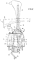
- Fig. 2
- eine vertikale Rückansicht der Wählhebelanordnung in Fig. 1 und
- Fig. 3
- eine vergrößerte Darstellung der erfindungswesentlichen Bauteile der Wählhebelkulisse.
- Eine Wählhebelanordnung 1 für ein automatisches Getriebe eines Kraftfahrzeuges besteht im wesentlichen aus einem am Fahrzeugboden (nicht gezeigt) befestigbaren Wählhebelgehäuse 2, das aus einem entsprechend hochwertigen Kunststoffmaterial im Spritzguß hergestellt wird. Das domartige Wählhebelgehäuse 2 weist etwa vertikale Seitenwände 3, 4, 5 und 6 auf, von denen die beiden seitlichen Seitenwände 3 und 5 Lageröffnungen 7 und 8 für eine horizontale Querachse 9 aufweisen.
- Ein Wählhebel 10 weist oben einen Handgriff 11 mit einem Kontrollknopf 12 auf und ist unten mit einem Lagerungsbauteil 13 verbunden, mittels dem er auf der horizontalen Querachse 9 schwenkbar gelagert ist.
- Das domartige Wählhebelgehäuse 2 ist oben von einem parallelwandigen Rastenbauteil 14 überdeckt, in dessen Seitenwänden 15 und 16 Rastkulissen 17 und 18 angeordnet sind, die mit einer Rastvorrichtung in Form eines horizontalen Rastbolzens 19 zusammenwirken, der über eine entsprechende Verbindung (nur in gestrichelten Linien angedeutet) vom Kontrollknopf 12 her beeinflußbar ist.
- Die Wählhebelanordnung wird zum Fahrzeuginnenraum hin durch eine Abdeckblende 20 in stilistisch gefälliger Weise abgedeckt.
- Soweit die Wählhebelanordnung bisher beschrieben wurde, entspricht sie im wesentlichen einem herkömmlichen Aufbau, wobei das Lagerungsbauteil 13 sowohl sich oberhalb der horizontalen Querachse 9 als auch unterhalb erstreckende Arme aufweisen kann, die zum Anschluß der Bowdenzugverbindungen zum automatischen Getriebe herangezogen werden können, wobei je nachdem, ob die Bowdenzuganordnung oberhalb oder unterhalb der horizontalen Querachse 9 angeordnet wird, keine oder aber eine Umlenkung der Wählbewegungsrichtung auftritt.
- Der Lagerungsbauteil 13 ist hierbei mit einer Verbindungsanordnung 21 verbunden, die aus einem am Lagerungsbauteil 13 ausgebildeten ersten Zahnsegment 22 besteht, das mit einem zweiten Zahnsegment 23 in Eingriff steht, das in einer unteren horizontalen Querachse 24 angeordnet ist, die in Teilbereichen der sich nach unten erstreckenden Seitenwände 3 und 5 des Wählhebelgehäuses 2 schwenkbar aufgenommen ist. An der unteren horizontalen Querachse 24 ist drehfest ein Hebelarm 25 angeordnet, an dessem unteren Ende 26 die Bowdenzugverbindung 27 zum automatischen Getriebe angelenkt ist.
- Am Lagerungsbauteil 13 ist noch ein sich nach oben erstreckendes Nockensegment 28 mit einer Anzahl von Rasten 29 vorgesehen, die mit einer Federraste 30 zusammenwirken, um die Wählhebelpositionen genauer festzulegen.
- Die bisher beschriebene Wählhebelanordnung entspricht der Wählhebelanordnung, die den Ausgangspunkt der vorliegenden Erfindung darstellt und die in der DE-PS 43 05 015 beschrieben ist.
- Abweichend von dieser bekannten Ausführungsform weist die erfindungsgemäße Wählhebelanordnung Änderungen in der Rastkulisse und in der Rastanordnung auf, die nachfolgend im Zusammenhang mit der vergrößerten Darstellung in Fig. 3 näher erläutert werden.
- Gemäß der Erfindung ist die in dem parallelwandigen Rastenbauteil 14, in dessen Seitenwänden 15 und 16 ausgebildeten Rastkulissen 17 und 18, die mit einem horizontalen Rastbolzen 19 zusammenwirken, in besonderer Weise ausgebildet, die nunmehr erläutert wird.
- Die Rastausnehmungen der Rastkulisse bleiben in den Bereichen für die Wählhebelpositionen P, R, N und D unverändert und lediglich im Bereich der früheren Schaltpositionen 2 und 1 wird eine Änderung vorgenommen.
- Die früheren Schaltpositionen 2 und 1 konnten erst durch Betätigen des Kontrollknopfes 12 am Handgriff 11 des Wählhebels 10 angewählt werden. Der hierfür vorgesehene Sperrnocken ist mit 31 bezeichnet. Anschließend an den Sperrnocken 31 schließt sich gemäß der Erfindung ein dachartiger Winkelabschnitt 32 an, ausgehend von dessen Scheitel 33 sich zwei Schrägen 34 und 35 anschließen.
- Der federbelastete Rastbolzen 19 drängt in die Scheitelposition 33 des dachartigen Winkelabschnittes 34, 35 der Rastkulissen 17 und 18 und hält hierdurch den Wählhebel in seiner weiteren Neutrallage M.
- Wird der Wählhebel aus seiner Neutrallage M in eine vordere Position "+" bewegt, so betätigt er einen Endschalter 36, der zum Auslösen einer Aufwärtsschaltung vorgesehen ist. Wird der Wählhebel in eine hintere Position "-" bewegt, so betätigt er einen Endschalter 37, der zum Auslösen einer Abwärtsschaltung vorgesehen ist. Sobald die Handbetätigungskraft am Wählhebel aufhört, führt der federbelastete Rastbolzen 19 infolge der Schrägen 34 und 35 den Wählhebel wieder in seine Neutrallage M zurück.
- Es kann sein, daß die zur Betätigung des Rastbolzens 19 vorgesehene Federkraft aus Komfortgründen nicht so hoch gewählt werden kann, daß eine erwünschte schnelle Rückführung des Wählhebels in die Neutrallage M mit der gewünschten Kraft erfolgen kann, daher wird gemäß einer Weiterbildung der Erfindung vorgeschlagen, an dem am Lagerungsbauteil 13 vorhandenen Nockensegment 28 mit den Rasten 29 und der Federraste 30 die letzte der Rasten 38, die funktionsmäßig dem dachartigen Winkelabschnitt 33, 34 und 35 in der Rastkulisse entspricht, entsprechend angepaßt auszubilden und mit einer durch eine Doppelfederanordnung 39 verstärkte Rastrolle 40 zusammenwirken zu lassen, die die erwünschte sichere Rückstellbewegung des Wählhebels in seine Neutrallage M bewerkstelligt.
- Die eigentliche Steuerung des automatischen Getriebes von Kraftfahrzeugen mit einer manuellen Schaltmöglichkeit ist nicht unmittelbarer Gegenstand der Erfindung. Es ist jedoch selbstverständlich, daß die vom Fahrer durch Betätigung des Wählhebels nach vorne oder nach hinten gewünschten Aufwärtsschaltungen oder Abwärtsschaltungen vor einer Ausführung durch das elektrohydraulische Steuerungssystem des automatischen Getriebes dahingehend überprüft werden, ob sie ohne Beschädigung des Getriebes durchgeführt werden können. Das heißt, eine bei hoher Geschwindigkeit durch mehrmaliges Antippen des Wählhebels nach hinten, geforderte mehrfache Abwärtsschaltung wird nicht in einem Zuge durchgeführt sondern in einer Sequenz von aufeinanderfolgenden Schaltungen, sobald die entsprechende Geschwindigkeit des Kraftfahrzeuges erreicht ist, bei der die entsprechende Abwärtsschaltung ohne Gefahr einer Beschädigung des Getriebes erfolgen kann. Das gleiche gilt sinngemäß für Aufwärtsschaltungen, die durch eine Vielzahl von Tippbewegungen nach vorne gewünscht werden.
Claims (2)
- Wählhebelanordnung für automatische Getriebe von Kraftfahrzeugen, mit einer manuellen Schaltmöglichkeit, mit einem in einer Schaltkulisse nur in einer Ebene nach vorn oder nach hinten in die bekannten Positionen (P, R, N und D sowie 2 und 1) bewegbaren Wählhebel (10), der anschließend an die Position (D) in eine weitere Neutrallage (M) bringbar ist, aus der er in eine vordere Position "+", einen eine Aufwärtsschaltung bewirkenden Schalter (36) betätigend und in eine hintere Position "-", einen eine Abwärtsschaltung bewirkenden Schalter (37) betätigend unter federbelasteter Rückkehrbewegung bringbar ist,
dadurch kennzeichnet, daß- der Wählhebel (10) in einer Rastkulisse (17/18) aus der Position (D) nur durch Betätigen eines Sperrknopfes (12) am Handgriff (11) zum Betätigen eines federbelasteten Sperrstiftes (19), der mit der Rastkulisse (17/18) zusammenwirkt, nach Überwinden eines Sperrnockens (31) in den Bereich der weiteren Neutrallage (M) bringbar ist,- an der Rastkulisse (17/18) die weitere Neutrallage (M) durch einen dachartigen Winkelabschnitt (32) ausgebildet ist und- der federbelastete, mit der Rastkulisse (17/18) zusammenwirkende Sperrstift (19) in Neutrallage (M) im Scheitel (33) des Winkelabschnittes (32) steht und nach Verlagerung nach vorn "+" oder nach hinten "-" durch die Schrägen (34 und 35) federbelastet in die Neutrallage (M) zurückgestellt wird. - Wählhebelanordnung nach Anspruch 1,
dadurch kennzeichnet, daß- an einem Lagerungsbauteil (13) im Bereich eines Nockensegmentes (28) mit einer Anzahl von Rasten (29) und einer Federraste (30) die der weiteren Neutrallage (M) entsprechende letzte Raste (38) eine Rückkehrbewegung des federbelasteten Sperrstiftes (19) unterstützend ausgebildet ist und mit einer Doppelfederanordnung (39) und einer Rastrolle (40) zusammenwirkt.
Applications Claiming Priority (2)
| Application Number | Priority Date | Filing Date | Title |
|---|---|---|---|
| DE19513397 | 1995-04-08 | ||
| DE19513397 | 1995-04-08 |
Publications (3)
| Publication Number | Publication Date |
|---|---|
| EP0736408A2 true EP0736408A2 (de) | 1996-10-09 |
| EP0736408A3 EP0736408A3 (de) | 1997-08-20 |
| EP0736408B1 EP0736408B1 (de) | 1999-01-13 |
Family
ID=7759269
Family Applications (1)
| Application Number | Title | Priority Date | Filing Date |
|---|---|---|---|
| EP96104275A Expired - Lifetime EP0736408B1 (de) | 1995-04-08 | 1996-03-18 | Wählhebelanordnung für automatische Getriebe für Kraftfahrzeuge mit manueller Schaltmöglichkeit |
Country Status (3)
| Country | Link |
|---|---|
| US (1) | US5682789A (de) |
| EP (1) | EP0736408B1 (de) |
| DE (1) | DE59601125D1 (de) |
Cited By (4)
| Publication number | Priority date | Publication date | Assignee | Title |
|---|---|---|---|---|
| EP0718527A3 (de) * | 1994-12-22 | 1997-06-04 | Bayerische Motoren Werke Ag | Schalteinrichtung für ein Kraftfahrzeug mit einem automatischen Getriebe |
| DE19726370C1 (de) * | 1997-06-21 | 1998-11-19 | Ford Global Tech Inc | Wählhebelanordnung für ein automatisches Getriebe von Kraftfahrzeugen |
| US20100326225A1 (en) * | 2009-06-25 | 2010-12-30 | Ford Global Technologies, Llc | Selector Lever Arrangement for Automatic Transmissions of Motor Vehicles |
| WO2019201675A1 (de) * | 2018-04-16 | 2019-10-24 | Zf Friedrichshafen Ag | Schaltelement zur aufnahme in eine gehäuseeinrichtung zum einstellen einer getriebeeinstellung für ein fahrzeug, schaltvorrichtung für ein fahrzeug, verfahren zum herstellen und verfahren zum betreiben einer solchen schaltvorrichtung |
Families Citing this family (24)
| Publication number | Priority date | Publication date | Assignee | Title |
|---|---|---|---|---|
| JP2916889B2 (ja) * | 1996-01-11 | 1999-07-05 | ナイルス部品株式会社 | 車両の変速操作装置 |
| IT1286288B1 (it) * | 1996-03-29 | 1998-07-08 | Roltra Morse Spa | Dispositivo di comando per un cambio automatico |
| JP3725634B2 (ja) * | 1996-09-30 | 2005-12-14 | マツダ株式会社 | 自動変速機の変速操作入力装置 |
| US5799539A (en) * | 1997-01-21 | 1998-09-01 | Ford Global Technologies, Inc. | Manually shifted automatic transmission lever |
| US5887485A (en) * | 1997-07-01 | 1999-03-30 | Prince Corporation | Vehicle console with built-in vehicle transmission shifter having cable tension adjustment mechanism and method |
| JP3185720B2 (ja) * | 1997-07-29 | 2001-07-11 | 日産自動車株式会社 | マニュアルシフト機能付き自動変速機の制御回路 |
| DE69826790T2 (de) * | 1997-07-29 | 2005-02-10 | Nissan Motor Co. Ltd., Yokohama | Schalteinrichtung für ein automatisches Getriebe |
| DE19736406B4 (de) * | 1997-08-21 | 2007-05-16 | Siemens Ag | Einrichtung zum Steuern eines automatischen Getriebes für ein Kraftfahrzeug |
| US6568294B2 (en) * | 2000-02-22 | 2003-05-27 | Grand Haven Stamped Products, Division Of Jsj Corporation | Shifter with automatic and manual shift modes and with shift position indicators |
| KR100380059B1 (ko) * | 2000-09-04 | 2003-04-14 | 현대자동차주식회사 | 자동변속기용 셀렉터 레버유닛의 쉬프트 스위치 조작장치 |
| JP3875483B2 (ja) * | 2000-11-13 | 2007-01-31 | 本田技研工業株式会社 | パーキングブレーキの操作レバー装置 |
| KR100391644B1 (ko) * | 2000-12-28 | 2003-07-12 | 현대자동차주식회사 | 자동변속기의 변속조작장치 |
| US6694590B1 (en) * | 2002-03-29 | 2004-02-24 | Honda Giken Kogyo Kabushiki Kaisha | Method of setting automotive transmission gear selector position |
| JP2005273819A (ja) * | 2004-03-25 | 2005-10-06 | Atsumi Tec:Kk | 車両用自動変速操作装置 |
| US20050223834A1 (en) * | 2004-03-30 | 2005-10-13 | Nissan Technical Center North America, Inc. | Inline automatic/manual shifter |
| DE502005011121D1 (de) * | 2005-01-05 | 2011-04-28 | Ford Global Tech Llc | Wählhebelanordnung für ein Automatikgetriebe |
| FR2883229B1 (fr) * | 2005-03-17 | 2007-06-15 | Renault Sas | Dispositif de commande deportee d'une boite de vitesses automatique permettant une commande manuelle |
| US7597022B2 (en) * | 2006-05-09 | 2009-10-06 | Dura Global Technologies, Inc. | Easy release mechanism at park position for automatic transmission shifter |
| US9032830B2 (en) * | 2010-10-29 | 2015-05-19 | Ford Global Technologies, Llc | Transmission shift selector assembly |
| WO2012068173A2 (en) * | 2010-11-15 | 2012-05-24 | Benjamin Francis Polito | Centrifugal brake for overspeed protection |
| US9091340B2 (en) * | 2011-05-11 | 2015-07-28 | GM Global Technology Operations LLC | Latching shifter with override feature |
| US8960040B2 (en) | 2011-09-14 | 2015-02-24 | GM Global Technology Operations LLC | Electronic shifter with adaptive position |
| USD740732S1 (en) * | 2013-07-18 | 2015-10-13 | Volvo Car Corporation | Automobile gear shift |
| US10012307B2 (en) * | 2016-02-25 | 2018-07-03 | Fca Us Llc | Automatic transmission shifter with speed sensitive damping |
Family Cites Families (8)
| Publication number | Priority date | Publication date | Assignee | Title |
|---|---|---|---|---|
| US4370897A (en) * | 1980-09-22 | 1983-02-01 | American Industries, Inc. | Dual mode shifter for automatic transmissions |
| JPS5940047A (ja) * | 1982-08-31 | 1984-03-05 | Fuji Heavy Ind Ltd | オ−トクラツチ車の変速操作機構 |
| DE3807881A1 (de) * | 1988-03-10 | 1989-09-21 | Porsche Ag | Schaltvorrichtung fuer ein automatikgetriebe eines kraftfahrzeugs |
| DE4005588C2 (de) * | 1990-02-22 | 1995-03-23 | Porsche Ag | Schaltvorrichtung für ein automatisches Getriebe |
| JP3058989B2 (ja) * | 1992-07-03 | 2000-07-04 | マツダ株式会社 | 自動変速機の制御装置 |
| FR2705129B1 (fr) * | 1993-05-11 | 1995-08-11 | Peugeot | Dispositif formant commande de vitesses pour boîte de vitesses automatique de véhicule. |
| US5388476A (en) * | 1993-06-15 | 1995-02-14 | Agco Corporation | Gearshift mechanism |
| DE4446079A1 (de) * | 1994-12-22 | 1996-06-27 | Bayerische Motoren Werke Ag | Schalteinrichtung für ein Kraftfahrzeug mit einem automatischen Getriebe |
-
1996
- 1996-03-18 DE DE59601125T patent/DE59601125D1/de not_active Expired - Fee Related
- 1996-03-18 EP EP96104275A patent/EP0736408B1/de not_active Expired - Lifetime
- 1996-04-02 US US08/626,587 patent/US5682789A/en not_active Expired - Fee Related
Cited By (5)
| Publication number | Priority date | Publication date | Assignee | Title |
|---|---|---|---|---|
| EP0718527A3 (de) * | 1994-12-22 | 1997-06-04 | Bayerische Motoren Werke Ag | Schalteinrichtung für ein Kraftfahrzeug mit einem automatischen Getriebe |
| DE19726370C1 (de) * | 1997-06-21 | 1998-11-19 | Ford Global Tech Inc | Wählhebelanordnung für ein automatisches Getriebe von Kraftfahrzeugen |
| US20100326225A1 (en) * | 2009-06-25 | 2010-12-30 | Ford Global Technologies, Llc | Selector Lever Arrangement for Automatic Transmissions of Motor Vehicles |
| US8453535B2 (en) * | 2009-06-25 | 2013-06-04 | Ford Global Technologies, Llc | Selector lever arrangement for automatic transmissions of motor vehicles |
| WO2019201675A1 (de) * | 2018-04-16 | 2019-10-24 | Zf Friedrichshafen Ag | Schaltelement zur aufnahme in eine gehäuseeinrichtung zum einstellen einer getriebeeinstellung für ein fahrzeug, schaltvorrichtung für ein fahrzeug, verfahren zum herstellen und verfahren zum betreiben einer solchen schaltvorrichtung |
Also Published As
| Publication number | Publication date |
|---|---|
| US5682789A (en) | 1997-11-04 |
| DE59601125D1 (de) | 1999-02-25 |
| EP0736408A3 (de) | 1997-08-20 |
| EP0736408B1 (de) | 1999-01-13 |
Similar Documents
| Publication | Publication Date | Title |
|---|---|---|
| EP0736408B1 (de) | Wählhebelanordnung für automatische Getriebe für Kraftfahrzeuge mit manueller Schaltmöglichkeit | |
| DE4426207C1 (de) | Wähleinrichtung für ein Automatikgetriebe eines Kraftfahrzeugs | |
| DE4005588C2 (de) | Schaltvorrichtung für ein automatisches Getriebe | |
| DE3927922C2 (de) | Schaltvorrichtung für ein Kraftfahrzeuggetriebe | |
| DE10064027C2 (de) | Schaltsteuervorrichtung einer Wählhebeleinrichtung eines Kraftfahreug-Automatikgetriebes | |
| DE3717675C5 (de) | Schalteinrichtung für ein Kraftfahrzeug mit automatischem Getriebe | |
| DE19526059C2 (de) | Schaltvorrichtung für ein automatisches Getriebe eines Kraftfahrzeugs | |
| DE69618556T2 (de) | Schaltbetätigung zum manuellen schalten eines automatikgetriebes | |
| DE19850685A1 (de) | Wähleinrichtung für ein automatisches Getriebe eines Kraftfahrzeugs | |
| DE2004249B2 (de) | Getriebeschalthebel-Baugruppe für ein mehrgängiges Fahrzeuggetriebe | |
| DE4305015C1 (de) | Wählhebelanordnung für ein automatisches Getriebe eines Kraftfahrzeuges | |
| EP0052794B1 (de) | Schaltvorrichtung für den Antrieb eines Nutzfahrzeuges | |
| DE69008167T2 (de) | Gangschalthebel für ein fahrzeuggetriebe. | |
| DE19620515C2 (de) | Schaltvorrichtung für ein Automatikgetriebe eines Kraftfahrzeuges | |
| DE3046689C2 (de) | Rückwärtsgangsperre für ein Kraftfahrzeug-Schaltgetriebe | |
| EP0616153A2 (de) | Schaltvorrichtung für ein Handschaltgetriebe eines Kraftfahrzeuges | |
| DE69402101T2 (de) | Gangschaltungseinrichtung für ein automatisches Kraftfahrzeuggetriebe | |
| DE2653035C3 (de) | Schaltvorrichtung für ein Kraftfahrzeugwechselgetriebe | |
| DE68910890T2 (de) | Mechanismus und dessen arbeitsweise zum positionieren eines gangschalthebels in parkstellung. | |
| DE19754250B4 (de) | Betätigungsvorrichtung zur Anwahl von Fahrstufen und zur manuellen Schaltung von Übersetzungsverhältnissen eines Automatikgetriebes | |
| DE4128161A1 (de) | Schalteinrichtung zur manuellen betaetigung eines mehrgaengigen kfz-wechselgetriebes mit rueckwaertsgang | |
| EP0718527B1 (de) | Schalteinrichtung für ein Kraftfahrzeug mit einem automatischen Getriebe | |
| DE69901872T2 (de) | Schalthebel für ein Automatgetriebe eines Kraftsfahrzeugs | |
| DE19849076A1 (de) | Wähleinrichtung für ein automatisch geschaltetes Getriebe eines Kraftfahrzeugs | |
| DE102004060232A1 (de) | Elektrische Schalteinrichtung für ein automatisiertes Getriebe |
Legal Events
| Date | Code | Title | Description |
|---|---|---|---|
| PUAI | Public reference made under article 153(3) epc to a published international application that has entered the european phase |
Free format text: ORIGINAL CODE: 0009012 |
|
| AK | Designated contracting states |
Kind code of ref document: A2 Designated state(s): DE FR GB |
|
| PUAL | Search report despatched |
Free format text: ORIGINAL CODE: 0009013 |
|
| AK | Designated contracting states |
Kind code of ref document: A3 Designated state(s): DE FR GB |
|
| 17P | Request for examination filed |
Effective date: 19970705 |
|
| 17Q | First examination report despatched |
Effective date: 19971008 |
|
| GRAG | Despatch of communication of intention to grant |
Free format text: ORIGINAL CODE: EPIDOS AGRA |
|
| GRAG | Despatch of communication of intention to grant |
Free format text: ORIGINAL CODE: EPIDOS AGRA |
|
| GRAG | Despatch of communication of intention to grant |
Free format text: ORIGINAL CODE: EPIDOS AGRA |
|
| GRAH | Despatch of communication of intention to grant a patent |
Free format text: ORIGINAL CODE: EPIDOS IGRA |
|
| GRAH | Despatch of communication of intention to grant a patent |
Free format text: ORIGINAL CODE: EPIDOS IGRA |
|
| GRAH | Despatch of communication of intention to grant a patent |
Free format text: ORIGINAL CODE: EPIDOS IGRA |
|
| RAP1 | Party data changed (applicant data changed or rights of an application transferred) |
Owner name: FORD GLOBAL TECHNOLOGIES, INC. |
|
| GRAA | (expected) grant |
Free format text: ORIGINAL CODE: 0009210 |
|
| AK | Designated contracting states |
Kind code of ref document: B1 Designated state(s): DE FR GB |
|
| REF | Corresponds to: |
Ref document number: 59601125 Country of ref document: DE Date of ref document: 19990225 |
|
| GBT | Gb: translation of ep patent filed (gb section 77(6)(a)/1977) |
Effective date: 19990204 |
|
| ET | Fr: translation filed | ||
| PLBE | No opposition filed within time limit |
Free format text: ORIGINAL CODE: 0009261 |
|
| STAA | Information on the status of an ep patent application or granted ep patent |
Free format text: STATUS: NO OPPOSITION FILED WITHIN TIME LIMIT |
|
| 26N | No opposition filed | ||
| REG | Reference to a national code |
Ref country code: GB Ref legal event code: IF02 |
|
| REG | Reference to a national code |
Ref country code: GB Ref legal event code: 732E |
|
| PGFP | Annual fee paid to national office [announced via postgrant information from national office to epo] |
Ref country code: FR Payment date: 20050302 Year of fee payment: 10 |
|
| REG | Reference to a national code |
Ref country code: FR Ref legal event code: TP |
|
| PGFP | Annual fee paid to national office [announced via postgrant information from national office to epo] |
Ref country code: GB Payment date: 20060206 Year of fee payment: 11 |
|
| PGFP | Annual fee paid to national office [announced via postgrant information from national office to epo] |
Ref country code: DE Payment date: 20060330 Year of fee payment: 11 |
|
| GBPC | Gb: european patent ceased through non-payment of renewal fee |
Effective date: 20070318 |
|
| REG | Reference to a national code |
Ref country code: FR Ref legal event code: ST Effective date: 20071130 |
|
| PG25 | Lapsed in a contracting state [announced via postgrant information from national office to epo] |
Ref country code: DE Free format text: LAPSE BECAUSE OF NON-PAYMENT OF DUE FEES Effective date: 20071002 |
|
| PG25 | Lapsed in a contracting state [announced via postgrant information from national office to epo] |
Ref country code: GB Free format text: LAPSE BECAUSE OF NON-PAYMENT OF DUE FEES Effective date: 20070318 |
|
| PG25 | Lapsed in a contracting state [announced via postgrant information from national office to epo] |
Ref country code: FR Free format text: LAPSE BECAUSE OF NON-PAYMENT OF DUE FEES Effective date: 20070402 |
|
| PG25 | Lapsed in a contracting state [announced via postgrant information from national office to epo] |
Ref country code: FR Free format text: LAPSE BECAUSE OF NON-PAYMENT OF DUE FEES Effective date: 20060331 |