EP0735272B1 - Kreiselpumpe mit Entlüftung - Google Patents
Kreiselpumpe mit Entlüftung Download PDFInfo
- Publication number
- EP0735272B1 EP0735272B1 EP96104659A EP96104659A EP0735272B1 EP 0735272 B1 EP0735272 B1 EP 0735272B1 EP 96104659 A EP96104659 A EP 96104659A EP 96104659 A EP96104659 A EP 96104659A EP 0735272 B1 EP0735272 B1 EP 0735272B1
- Authority
- EP
- European Patent Office
- Prior art keywords
- centrifugal pump
- insert
- pump
- pump according
- venting device
- Prior art date
- Legal status (The legal status is an assumption and is not a legal conclusion. Google has not performed a legal analysis and makes no representation as to the accuracy of the status listed.)
- Expired - Lifetime
Links
- 238000013022 venting Methods 0.000 title claims description 17
- 238000010438 heat treatment Methods 0.000 claims description 11
- XLYOFNOQVPJJNP-UHFFFAOYSA-N water Substances O XLYOFNOQVPJJNP-UHFFFAOYSA-N 0.000 claims description 5
- 238000009423 ventilation Methods 0.000 description 9
- 230000002441 reversible effect Effects 0.000 description 4
- 230000008901 benefit Effects 0.000 description 2
- 230000007547 defect Effects 0.000 description 1
- 239000008236 heating water Substances 0.000 description 1
- 238000012423 maintenance Methods 0.000 description 1
- 238000004519 manufacturing process Methods 0.000 description 1
Images


Classifications
-
- F—MECHANICAL ENGINEERING; LIGHTING; HEATING; WEAPONS; BLASTING
- F04—POSITIVE - DISPLACEMENT MACHINES FOR LIQUIDS; PUMPS FOR LIQUIDS OR ELASTIC FLUIDS
- F04D—NON-POSITIVE-DISPLACEMENT PUMPS
- F04D29/00—Details, component parts, or accessories
- F04D29/40—Casings; Connections of working fluid
- F04D29/42—Casings; Connections of working fluid for radial or helico-centrifugal pumps
- F04D29/44—Fluid-guiding means, e.g. diffusers
- F04D29/445—Fluid-guiding means, e.g. diffusers especially adapted for liquid pumps
-
- F—MECHANICAL ENGINEERING; LIGHTING; HEATING; WEAPONS; BLASTING
- F04—POSITIVE - DISPLACEMENT MACHINES FOR LIQUIDS; PUMPS FOR LIQUIDS OR ELASTIC FLUIDS
- F04D—NON-POSITIVE-DISPLACEMENT PUMPS
- F04D29/00—Details, component parts, or accessories
- F04D29/40—Casings; Connections of working fluid
- F04D29/42—Casings; Connections of working fluid for radial or helico-centrifugal pumps
- F04D29/426—Casings; Connections of working fluid for radial or helico-centrifugal pumps especially adapted for liquid pumps
- F04D29/4273—Casings; Connections of working fluid for radial or helico-centrifugal pumps especially adapted for liquid pumps suction eyes
-
- F—MECHANICAL ENGINEERING; LIGHTING; HEATING; WEAPONS; BLASTING
- F04—POSITIVE - DISPLACEMENT MACHINES FOR LIQUIDS; PUMPS FOR LIQUIDS OR ELASTIC FLUIDS
- F04D—NON-POSITIVE-DISPLACEMENT PUMPS
- F04D9/00—Priming; Preventing vapour lock
- F04D9/001—Preventing vapour lock
- F04D9/002—Preventing vapour lock by means in the very pump
- F04D9/003—Preventing vapour lock by means in the very pump separating and removing the vapour
Definitions
- the invention relates to a centrifugal pump with a a housing arranged interchangeable insert, the has an inlet and an outlet which in one side flat and open side wall of the housing lie, and with a top on the outer edge of the housing (3) attached ventilation device (9), below which the Insert (13) is arranged.
- Pumps are known to change their design
- Direction of rotation or by actuating internal pumps can alternately supply different circuits.
- the valves are either hydraulic or mechanically operated.
- a centrifugal pump is known from DE 36 24 917, which is a housing with a side flat and open Has side wall in which an insert can be replaced can be introduced.
- DE 36 24 917 is a housing with a side flat and open Has side wall in which an insert can be replaced can be introduced.
- pressure-side and suction-side channels individually, so that it is possible with such a pump, for example is, they with two suction and a pressure nozzle or to operate in reverse. So this pump is too Suitable for supplying several circuits.
- the ventilation system at the highest points in the heating system be provided where the air is removed from time to time can be. Because this type of venting is unfriendly to maintenance, it is known in the pump Vent valves, so-called quick breather integrate. These quick exhaust ventilate the air during operation of the pump continuously to the environment.
- DE-U-94 16 551 for example, includes a pump known such a vent.
- FR 1 532 578 shows one pump with another Embodiment of a breather.
- the object of the invention is to provide a centrifugal pump create through an interchangeable insert for Supply of multiple circuits can be used and which is also the venting of each circuit ensures.
- This task is characterized by the characteristics of the Claim 1 solved.
- the advantage of such a pump is that the pump is universal can be adapted to the needs of the user without the ventilation device must be replaced. Here can use this pump to operate multiple system circuits simultaneously be vented. The ventilation takes place automatically, without the user or a heating installer System must wait. This means effort and costs lowered.
- the centrifugal pump according to the invention is in a special one Embodiment designed to be in two Direction of rotation can be operated and so two can supply independent circuits. Therefore, it can be simply replace it with an existing double pump.
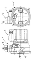
- the centrifugal pump 1 is operated by an electric motor 2, the direction of rotation in a special embodiment is reversible.
- the electric motor is on the outer housing 3 attached and operates an impeller 5 via a shaft.
- the electric motor is advantageously a canned motor.
- the housing 3 has a flange 4 sealed against the heating system.
- the design of the pump is flange 4 with an outlet 7 and provided with an inlet 8.
- Inlet 8 and outlet 7 are located on a side flat and open side wall 10 of the housing 3.
- the suction side of the pump 1 is by means of a venting device 9 vented on the top Outside edge of the housing 3 is attached.
- FIG. 2 shows two sections through the pump 1 described.
- Section A-A shows the venting device 9 which is mounted on top of the housing 3.
- the Venting device 9 has a float 11, the one Valve 12 actuated, through which the existing air escape can.
- the housing 3 there is an insert 13 which in the special embodiment is in two parts. One part is formed by the flange 4, which in the housing is sufficient and in the area of the ventilation device 9 Has passage openings 14. Through these openings 14 the water at the venting device 9 passed by, so that the air can collect. At a special embodiment, the ventilation either on the pressure side or on the suction side.
- a second part 15 of the insert 13 In addition to the flange 4 is a second part 15 of the insert 13 arranged.
- This hydraulic insert 15 points in this embodiment has a spiral channel, through which the impeller 5 the water to the pressure side promoted.
- the hydraulic insert 15 is interchangeable in introduced the housing 3.
- the flange 4 is on the inside reinforced with ribs 16.
- the section B-B shows the impeller 5 on the suction side Water is supplied and this through the hydraulic use 15 defined channels on the Pressure port 8 promoted.
- the venting device is designed so that it in each case at least one channel through which pressure or Vented on the suction side.
- FIG. 3 shows a pump 1 with the described Housing 3 and the electric motor 2.
- the hydraulic use 15 and the flange 4 are designed so that the pump two Inlets 7 (suction ports) and one outlet 8 (pressure ports) having.
- a valve 17 closes either one or the other inlet 7.
- the valve 17 has a seal 18 on and is pivotally mounted on an axis 19.
- the Venting device 9 ventilates both suction sides the pump.
- Inserts 13 are used in the pump housing 3 . If the direction of rotation of the The motor 15 is reversible (reversing pump), the insert 15 a valve on which switches between two Channels. So the pump with two suction and a pressure port or vice versa. The Venting of the channel through which the flow is flowing is carried out by the Venting device ensured.
- any use is conceivable that for example the water in several different Promote channels at the same time.
- the ventilation can again on each channel flowed through.
Landscapes
- Engineering & Computer Science (AREA)
- Mechanical Engineering (AREA)
- General Engineering & Computer Science (AREA)
- Structures Of Non-Positive Displacement Pumps (AREA)
Description
- Fig.1.
- eine Kreiselpumpe mit einer Entlüftungsvorrichtung, welche die Saugseite entlüftet
- Fig.2.
- einen Schnitt durch eine Kreiselpumpe mit einer Entlüftungsvorrichtung und einem Druck- und einem Saugstutzen
- Fig.3.
- eine Kreiselpumpe, deren Laufrichtung umkehrbar ist, mit einer Entlüftungsvorrichtung, die zwei Saugseiten entlüftet
Claims (6)
- Kreiselmotorpumpe mit einem in einem Gehäuse (3) angeordneten auswechselbaren Einsatz (13), der einen Einlaß (8) und einen Auslaß (7) aufweist, die in einer seitlichen flachen und offenen Seitenwand (10) des Gehäuses (3) liegen, und mit einer oben am Außenrand des Gehäuses (3) befestigten Entlüftungsvorrichtung (9), unterhalb derer der Einsatz (13) angeordnet ist,
dadurch gekennzeichnet, daß der Einsatz (13) zumindest im Bereich der Entlüftungsvorrichtung (9) Durchtrittsöffnungen (14) aufweist und den Wasserstrom druckseitig auf mehrere Kanäle verteilt. - Kreiselmotorpumpe nach Anspruch 1,
dadurch gekennzeichnet, daß der Einsatz (13) einen Flansch (4) aufweist, der an dem Gehäuse (3) anliegt und die Kreiselmotorpumpe gegen das Heizungssystem abdichtet. - Kreiselmotorpumpe nach Anspruch 1,
dadurch gekennzeichnet, daß der Einsatz (13) einen das Laufrad (5) umgebenden hydraulischen Einsatz (15) aufweist, der einen wasserführenden Kanal bildet. - Kreiselmotorpumpe nach Anspruch 3,
dadurch gekennzeichnet, daß der hydraulische Einsatz (15) einen spiralförmigen Kanal bildet. - Kreiselmotorpumpe nach einem der vorherigen Ansprüche,
dadurch gekennzeichnet, daß die Entlüftungsvorrichtung (9) mindestens einen druckseitigen oder mindestens einen saugseitigen Kanal entlüftet. - Kreiselmotorpumpe nach einem der vorherigen Ansprüche,
dadurch gekennzeichnet, daß der Einsatz (13) Kanäle aufweist, die durch ein Ventil getrennt sind.
Applications Claiming Priority (2)
| Application Number | Priority Date | Filing Date | Title |
|---|---|---|---|
| DE19511027A DE19511027A1 (de) | 1995-03-28 | 1995-03-28 | Kreiselpumpe mit Entlüftung |
| DE19511027 | 1995-03-28 |
Publications (2)
| Publication Number | Publication Date |
|---|---|
| EP0735272A1 EP0735272A1 (de) | 1996-10-02 |
| EP0735272B1 true EP0735272B1 (de) | 1999-06-02 |
Family
ID=7757759
Family Applications (1)
| Application Number | Title | Priority Date | Filing Date |
|---|---|---|---|
| EP96104659A Expired - Lifetime EP0735272B1 (de) | 1995-03-28 | 1996-03-23 | Kreiselpumpe mit Entlüftung |
Country Status (2)
| Country | Link |
|---|---|
| EP (1) | EP0735272B1 (de) |
| DE (2) | DE19511027A1 (de) |
Families Citing this family (3)
| Publication number | Priority date | Publication date | Assignee | Title |
|---|---|---|---|---|
| DE102008052884A1 (de) * | 2008-10-23 | 2010-05-06 | Wilo Se | Pumpengehäuse |
| EP2990651B1 (de) * | 2014-08-25 | 2018-07-11 | Grundfos Holding A/S | Pumpengehäuse |
| EP3364043B1 (de) * | 2017-02-20 | 2019-11-20 | Grundfos Holding A/S | Pumpenaggregat mit integrierter entlüftung- und entleerungseinheit |
Family Cites Families (8)
| Publication number | Priority date | Publication date | Assignee | Title |
|---|---|---|---|---|
| FR1532578A (fr) * | 1967-05-31 | 1968-07-12 | Chaffoteaux Et Maury | Perfectionnements aux pompes |
| GB1458192A (de) * | 1973-05-09 | 1976-12-08 | Sealed Motor | |
| DE8102304U1 (de) * | 1981-01-30 | 1981-07-02 | Grundfos A/S, 8850 Bjerringbro | Pumpe mit typenschild |
| DE3624917A1 (de) * | 1985-09-21 | 1987-03-26 | Oplaender Wilo Werk Gmbh | Kreiselpumpe |
| DE3637040A1 (de) * | 1986-10-31 | 1988-05-19 | Grundfos Int | Kreiselpumpe als umwaelzpumpe fuer heizungsanlagen |
| DE4021410A1 (de) * | 1990-07-06 | 1992-01-16 | Oplaender Wilo Werk Gmbh | Doppel-kreiselpumpe |
| DE9208801U1 (de) * | 1992-07-01 | 1992-09-03 | Grundfos A/S, Bjerringbro | Pumpenaggregat |
| DE9416551U1 (de) * | 1994-10-14 | 1994-12-01 | Wilo Gmbh, 44263 Dortmund | Kreiselpumpe mit Verschraubung |
-
1995
- 1995-03-28 DE DE19511027A patent/DE19511027A1/de not_active Withdrawn
-
1996
- 1996-03-23 DE DE59602046T patent/DE59602046D1/de not_active Expired - Lifetime
- 1996-03-23 EP EP96104659A patent/EP0735272B1/de not_active Expired - Lifetime
Also Published As
| Publication number | Publication date |
|---|---|
| DE19511027A1 (de) | 1996-10-02 |
| DE59602046D1 (de) | 1999-07-08 |
| EP0735272A1 (de) | 1996-10-02 |
Similar Documents
| Publication | Publication Date | Title |
|---|---|---|
| EP0464355B1 (de) | Doppel-Kreiselpumpe | |
| DE60012069T2 (de) | Kraftfahrzeugklimaanlage | |
| DE69607367T2 (de) | Apparat mit fluidsteuerventil und druckquelle | |
| DE69016674T2 (de) | Wärmerückgewinnender ventilator. | |
| DE60204845T2 (de) | Waschflüssigkeitspumpe | |
| DE69829374T2 (de) | Verfahren und vorrichtung für eine umwälzpumpe | |
| CH649350A5 (de) | Pumpe oder geblaese, insbesondere fuer heizungs- und klimaanlagen. | |
| EP2290298A2 (de) | Einrichtung zum Umleiten eines Luftstroms insbesondere für eine Dunstabzugshaube | |
| DE3425616A1 (de) | Anordnung zur minimierung des kuehlfluessigkeitsverbrauches insbes. bei fluessigkeitsring-vakuumpumpen o.dgl. | |
| DE102005033224A1 (de) | Dunstabzugshaube und Dunstabzugsvorrichtung | |
| DE202007001644U1 (de) | Modular aufgebaute Lüftungseinrichtung für den Einsatz im Reinraum | |
| DE102017218345A1 (de) | Verfahren zur verteilung von luftventilation in einem fahrzeug | |
| DE3405584C2 (de) | ||
| DE19511027A1 (de) | Kreiselpumpe mit Entlüftung | |
| WO1994008141A1 (de) | Verfahren zum betrieb einer klauenvakuumpumpe und für die durchführung dieses betriebsverfahrens geeignete klauenvakuumpumpe | |
| EP3364043B1 (de) | Pumpenaggregat mit integrierter entlüftung- und entleerungseinheit | |
| DE69418559T2 (de) | Einrichtung von Rückschlagventilen bei Flüssigkeitsringpumpen | |
| AT394434B (de) | Geblaeseanordnung | |
| DE69221415T2 (de) | Schraubenkolben-Vakuumpumpe | |
| EP0791772B1 (de) | Dreiwegeventil für hydraulische Schnittstelle | |
| DE60207045T2 (de) | Wasserdurchfluss- regelventil | |
| EP2138748B1 (de) | Mehrkanal-Verteilventil | |
| DE102004010632A1 (de) | Kraftfahrzeug mit doppeltem Kühler | |
| DE19834270A1 (de) | Ventilatorkonvektor | |
| DE1604240C3 (de) | Gerät zum Heizen und/oder Kühlen von Raumluft |
Legal Events
| Date | Code | Title | Description |
|---|---|---|---|
| PUAI | Public reference made under article 153(3) epc to a published international application that has entered the european phase |
Free format text: ORIGINAL CODE: 0009012 |
|
| AK | Designated contracting states |
Kind code of ref document: A1 Designated state(s): BE DE FR GB IT |
|
| 17P | Request for examination filed |
Effective date: 19961029 |
|
| 17Q | First examination report despatched |
Effective date: 19980206 |
|
| GRAG | Despatch of communication of intention to grant |
Free format text: ORIGINAL CODE: EPIDOS AGRA |
|
| GRAG | Despatch of communication of intention to grant |
Free format text: ORIGINAL CODE: EPIDOS AGRA |
|
| GRAH | Despatch of communication of intention to grant a patent |
Free format text: ORIGINAL CODE: EPIDOS IGRA |
|
| GRAH | Despatch of communication of intention to grant a patent |
Free format text: ORIGINAL CODE: EPIDOS IGRA |
|
| GRAA | (expected) grant |
Free format text: ORIGINAL CODE: 0009210 |
|
| AK | Designated contracting states |
Kind code of ref document: B1 Designated state(s): BE DE FR GB IT |
|
| GBT | Gb: translation of ep patent filed (gb section 77(6)(a)/1977) |
Effective date: 19990603 |
|
| ET | Fr: translation filed | ||
| REF | Corresponds to: |
Ref document number: 59602046 Country of ref document: DE Date of ref document: 19990708 |
|
| ITF | It: translation for a ep patent filed | ||
| PLBE | No opposition filed within time limit |
Free format text: ORIGINAL CODE: 0009261 |
|
| STAA | Information on the status of an ep patent application or granted ep patent |
Free format text: STATUS: NO OPPOSITION FILED WITHIN TIME LIMIT |
|
| 26N | No opposition filed | ||
| REG | Reference to a national code |
Ref country code: GB Ref legal event code: IF02 |
|
| PGFP | Annual fee paid to national office [announced via postgrant information from national office to epo] |
Ref country code: BE Payment date: 20020408 Year of fee payment: 7 |
|
| PG25 | Lapsed in a contracting state [announced via postgrant information from national office to epo] |
Ref country code: BE Free format text: LAPSE BECAUSE OF NON-PAYMENT OF DUE FEES Effective date: 20030331 |
|
| BERE | Be: lapsed |
Owner name: *WILO G.M.B.H. Effective date: 20030331 |
|
| PGFP | Annual fee paid to national office [announced via postgrant information from national office to epo] |
Ref country code: FR Payment date: 20140311 Year of fee payment: 19 Ref country code: IT Payment date: 20140319 Year of fee payment: 19 |
|
| PGFP | Annual fee paid to national office [announced via postgrant information from national office to epo] |
Ref country code: GB Payment date: 20140319 Year of fee payment: 19 |
|
| PGFP | Annual fee paid to national office [announced via postgrant information from national office to epo] |
Ref country code: DE Payment date: 20140417 Year of fee payment: 19 |
|
| REG | Reference to a national code |
Ref country code: DE Ref legal event code: R119 Ref document number: 59602046 Country of ref document: DE |
|
| GBPC | Gb: european patent ceased through non-payment of renewal fee |
Effective date: 20150323 |
|
| PG25 | Lapsed in a contracting state [announced via postgrant information from national office to epo] |
Ref country code: IT Free format text: LAPSE BECAUSE OF NON-PAYMENT OF DUE FEES Effective date: 20150323 |
|
| REG | Reference to a national code |
Ref country code: FR Ref legal event code: ST Effective date: 20151130 |
|
| PG25 | Lapsed in a contracting state [announced via postgrant information from national office to epo] |
Ref country code: GB Free format text: LAPSE BECAUSE OF NON-PAYMENT OF DUE FEES Effective date: 20150323 Ref country code: DE Free format text: LAPSE BECAUSE OF NON-PAYMENT OF DUE FEES Effective date: 20151001 |
|
| PG25 | Lapsed in a contracting state [announced via postgrant information from national office to epo] |
Ref country code: FR Free format text: LAPSE BECAUSE OF NON-PAYMENT OF DUE FEES Effective date: 20150331 |