EP0733601A1 - Méthode et dispositif de revêtement de fibres - Google Patents
Méthode et dispositif de revêtement de fibres Download PDFInfo
- Publication number
- EP0733601A1 EP0733601A1 EP96103780A EP96103780A EP0733601A1 EP 0733601 A1 EP0733601 A1 EP 0733601A1 EP 96103780 A EP96103780 A EP 96103780A EP 96103780 A EP96103780 A EP 96103780A EP 0733601 A1 EP0733601 A1 EP 0733601A1
- Authority
- EP
- European Patent Office
- Prior art keywords
- fiber
- coating
- helium
- atmosphere
- liquid
- Prior art date
- Legal status (The legal status is an assumption and is not a legal conclusion. Google has not performed a legal analysis and makes no representation as to the accuracy of the status listed.)
- Granted
Links
- 239000000835 fiber Substances 0.000 title claims abstract description 88
- 238000000576 coating method Methods 0.000 title claims abstract description 83
- 239000011248 coating agent Substances 0.000 title claims abstract description 78
- 238000000034 method Methods 0.000 title claims abstract description 17
- 239000001307 helium Substances 0.000 claims abstract description 49
- 229910052734 helium Inorganic materials 0.000 claims abstract description 49
- SWQJXJOGLNCZEY-UHFFFAOYSA-N helium atom Chemical compound [He] SWQJXJOGLNCZEY-UHFFFAOYSA-N 0.000 claims abstract description 49
- 239000007788 liquid Substances 0.000 claims abstract description 41
- 239000007789 gas Substances 0.000 claims description 50
- 238000001816 cooling Methods 0.000 claims description 32
- 239000008199 coating composition Substances 0.000 claims description 7
- 239000007787 solid Substances 0.000 claims description 6
- 239000011521 glass Substances 0.000 claims description 5
- 239000011241 protective layer Substances 0.000 claims description 4
- 239000013307 optical fiber Substances 0.000 abstract description 24
- 239000000463 material Substances 0.000 abstract description 23
- 230000001681 protective effect Effects 0.000 abstract description 5
- 239000004033 plastic Substances 0.000 abstract description 3
- 230000008569 process Effects 0.000 abstract description 2
- 239000006223 plastic coating Substances 0.000 abstract 1
- 238000010926 purge Methods 0.000 description 21
- 230000015572 biosynthetic process Effects 0.000 description 7
- 239000000203 mixture Substances 0.000 description 7
- IJGRMHOSHXDMSA-UHFFFAOYSA-N Atomic nitrogen Chemical compound N#N IJGRMHOSHXDMSA-UHFFFAOYSA-N 0.000 description 6
- XKRFYHLGVUSROY-UHFFFAOYSA-N Argon Chemical compound [Ar] XKRFYHLGVUSROY-UHFFFAOYSA-N 0.000 description 5
- CURLTUGMZLYLDI-UHFFFAOYSA-N Carbon dioxide Chemical compound O=C=O CURLTUGMZLYLDI-UHFFFAOYSA-N 0.000 description 5
- 239000002826 coolant Substances 0.000 description 5
- 229910002092 carbon dioxide Inorganic materials 0.000 description 4
- PXBRQCKWGAHEHS-UHFFFAOYSA-N dichlorodifluoromethane Chemical compound FC(F)(Cl)Cl PXBRQCKWGAHEHS-UHFFFAOYSA-N 0.000 description 4
- 239000011253 protective coating Substances 0.000 description 4
- QVGXLLKOCUKJST-UHFFFAOYSA-N atomic oxygen Chemical compound [O] QVGXLLKOCUKJST-UHFFFAOYSA-N 0.000 description 3
- 238000012681 fiber drawing Methods 0.000 description 3
- 230000005499 meniscus Effects 0.000 description 3
- 229910052757 nitrogen Inorganic materials 0.000 description 3
- 239000001301 oxygen Substances 0.000 description 3
- 229910052760 oxygen Inorganic materials 0.000 description 3
- 229910052724 xenon Inorganic materials 0.000 description 3
- FHNFHKCVQCLJFQ-UHFFFAOYSA-N xenon atom Chemical compound [Xe] FHNFHKCVQCLJFQ-UHFFFAOYSA-N 0.000 description 3
- HEDRZPFGACZZDS-UHFFFAOYSA-N Chloroform Chemical compound ClC(Cl)Cl HEDRZPFGACZZDS-UHFFFAOYSA-N 0.000 description 2
- UFHFLCQGNIYNRP-UHFFFAOYSA-N Hydrogen Chemical compound [H][H] UFHFLCQGNIYNRP-UHFFFAOYSA-N 0.000 description 2
- 229910052786 argon Inorganic materials 0.000 description 2
- 150000008282 halocarbons Chemical class 0.000 description 2
- 239000001257 hydrogen Substances 0.000 description 2
- 229910052739 hydrogen Inorganic materials 0.000 description 2
- 229910052756 noble gas Inorganic materials 0.000 description 2
- 150000002835 noble gases Chemical class 0.000 description 2
- 230000003287 optical effect Effects 0.000 description 2
- NIXOWILDQLNWCW-UHFFFAOYSA-M Acrylate Chemical compound [O-]C(=O)C=C NIXOWILDQLNWCW-UHFFFAOYSA-M 0.000 description 1
- 239000006087 Silane Coupling Agent Substances 0.000 description 1
- 239000000654 additive Substances 0.000 description 1
- 230000008901 benefit Effects 0.000 description 1
- 239000001569 carbon dioxide Substances 0.000 description 1
- 239000013626 chemical specie Substances 0.000 description 1
- 239000003795 chemical substances by application Substances 0.000 description 1
- 238000005253 cladding Methods 0.000 description 1
- 239000011247 coating layer Substances 0.000 description 1
- 230000007547 defect Effects 0.000 description 1
- 229920006240 drawn fiber Polymers 0.000 description 1
- 230000008030 elimination Effects 0.000 description 1
- 238000003379 elimination reaction Methods 0.000 description 1
- 238000002474 experimental method Methods 0.000 description 1
- 229930195733 hydrocarbon Natural products 0.000 description 1
- 150000002430 hydrocarbons Chemical class 0.000 description 1
- 230000002401 inhibitory effect Effects 0.000 description 1
- 238000009413 insulation Methods 0.000 description 1
- 239000010410 layer Substances 0.000 description 1
- 230000007246 mechanism Effects 0.000 description 1
- 239000002184 metal Substances 0.000 description 1
- 239000006060 molten glass Substances 0.000 description 1
- 239000000178 monomer Substances 0.000 description 1
- 229910052754 neon Inorganic materials 0.000 description 1
- GKAOGPIIYCISHV-UHFFFAOYSA-N neon atom Chemical compound [Ne] GKAOGPIIYCISHV-UHFFFAOYSA-N 0.000 description 1
- 231100000252 nontoxic Toxicity 0.000 description 1
- 230000003000 nontoxic effect Effects 0.000 description 1
- 239000011368 organic material Substances 0.000 description 1
- 239000011148 porous material Substances 0.000 description 1
- 235000012239 silicon dioxide Nutrition 0.000 description 1
- 238000004513 sizing Methods 0.000 description 1
- 238000011144 upstream manufacturing Methods 0.000 description 1
- 230000000007 visual effect Effects 0.000 description 1
Images

Classifications
-
- C—CHEMISTRY; METALLURGY
- C03—GLASS; MINERAL OR SLAG WOOL
- C03C—CHEMICAL COMPOSITION OF GLASSES, GLAZES OR VITREOUS ENAMELS; SURFACE TREATMENT OF GLASS; SURFACE TREATMENT OF FIBRES OR FILAMENTS MADE FROM GLASS, MINERALS OR SLAGS; JOINING GLASS TO GLASS OR OTHER MATERIALS
- C03C25/00—Surface treatment of fibres or filaments made from glass, minerals or slags
- C03C25/10—Coating
- C03C25/12—General methods of coating; Devices therefor
- C03C25/18—Extrusion
-
- C—CHEMISTRY; METALLURGY
- C03—GLASS; MINERAL OR SLAG WOOL
- C03C—CHEMICAL COMPOSITION OF GLASSES, GLAZES OR VITREOUS ENAMELS; SURFACE TREATMENT OF GLASS; SURFACE TREATMENT OF FIBRES OR FILAMENTS MADE FROM GLASS, MINERALS OR SLAGS; JOINING GLASS TO GLASS OR OTHER MATERIALS
- C03C25/00—Surface treatment of fibres or filaments made from glass, minerals or slags
- C03C25/10—Coating
- C03C25/12—General methods of coating; Devices therefor
-
- C—CHEMISTRY; METALLURGY
- C03—GLASS; MINERAL OR SLAG WOOL
- C03B—MANUFACTURE, SHAPING, OR SUPPLEMENTARY PROCESSES
- C03B37/00—Manufacture or treatment of flakes, fibres, or filaments from softened glass, minerals, or slags
- C03B37/01—Manufacture of glass fibres or filaments
- C03B37/02—Manufacture of glass fibres or filaments by drawing or extruding, e.g. direct drawing of molten glass from nozzles; Cooling fins therefor
- C03B37/025—Manufacture of glass fibres or filaments by drawing or extruding, e.g. direct drawing of molten glass from nozzles; Cooling fins therefor from reheated softened tubes, rods, fibres or filaments, e.g. drawing fibres from preforms
- C03B37/027—Fibres composed of different sorts of glass, e.g. glass optical fibres
- C03B37/02718—Thermal treatment of the fibre during the drawing process, e.g. cooling
Definitions
- the present invention relates to the coating of fibers with liquid-applied organic materials which are thereafter cured to form solid protective organic coatings on the fibers, and more particularly, to the coating of glass optical waveguide fibers.
- Fibers are frequently provided with a coating for protection against mechanical damage, for insulation, for identification and for other purposes.
- An optical fiber for example, is drawn from a source such as a crucible or preform and then passes successively through a cooling tube, one or more coating means, and a draw mechanism such as a tractor; it is then wound on a spool.
- a diameter measuring means is located between the source and the cooling tube; another diameter measuring means is optionally located after the coating means.
- the drawn optical fiber should be provided with a protective coating prior to its coming into contact with any other surface such as the draw tractor.
- U.S. patent 4,792,347 (Deneka et al.), which is incorporated herein by reference, teaches a method for applying a protective coating to an optical fiber by applying a curable liquid coating material thereto and subsequently curing the liquid coating to form a protective plastic layer. Air is purged or displaced from the surface of the fiber prior to the application of the liquid coating material thereto by replacing air adjacent the fiber surface with a purge gas that preferably exhibits high solubility in the liquid coating material and resists bubble formation in the liquid coating layer as it is formed.
- suitable purge gases are nitrogen, carbon dioxide, and the Group VIII or so-called noble gases, e.g., xenon, neon, argon or the like, and that chemically inert halocarbon gases or vapors thereof, such as chloroform, Freon® halocarbons, or other chlorine- or fluorine-substituted hydrocarbons may also be considered.
- All of the purge gases mentioned in U.S. patent No. 4,704,307 displace the oxygen that is present in air and hence reduce its inhibiting effect on cure. For example, nitrogen does not reduce bubbles in air, although it is a safe and inexpensive gas to displace oxygen from above the coating. Argon functions in a similar manner.
- An object of the invention is to provide a method and apparatus for preventing the formation of bubbles in an optical fiber coating, which apparatus employs a gas that is readily accessible at optical fiber draw towers. Another object is to provide a method and apparatus for cooling a newly drawn optical fiber and simultaneously preventing the formation of bubbles in a coating applied to the optical fiber.
- the present invention provides a method for coating an optical fiber which aids in preventing bubble formation in the coating. Coatings are applied to fibers by drawing the fiber through a body of a curable liquid coating composition, removing excess coating liquid from the fiber and curing of the coating liquid to form a solid protective layer.
- the atmosphere surrounding the fiber at the point of entry thereof into the liquid coating composition comprises an amount of helium effective to reduce the occurrence of bubbles in the solid protective layer.
- the atmosphere can comprise substantially pure helium or a mixture of helium and at least one other gas. The helium atmosphere is more effective if it is directed toward the fiber in one or more jets to displace entrained air from the fiber.
- cooling means When an optical fiber is being drawn, it traverses cooling means prior to entering the coater. If the cooling means employs helium to cool the drawn fiber, helium exhausted from the cooling means can be fed to the apparatus that displaces air from the fiber.
- That end of the cooling means from which the cooled fiber exits can be situated immediately adjacent the housing that contains the liquid coating material so that air cannot become entrained with the fiber after it passes out of the cooling means and before it passes into the coating liquid.
- Fig. 1 schematically illustrates an optical fiber drawing system.
- Fig. 2 schematically illustrates optical fiber coating apparatus provided with means for displacing air from a fiber.
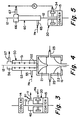
- Fig. 3 schematically illustrates optical fiber coating apparatus provided with means for evacuating the region surrounding the fiber prior to its passing into air displacing means.
- Fig. 4 schematically illustrates an apparatus wherein a single device simultaneously functions as a cooler and air displacing means.
- Fig. 5 schematically illustrates an apparatus for utilizing recycled helium from a fiber cooling means as the purge gas.
- FIG. 1 A fiber drawing system into which the present invention is incorporated is shown in Fig. 1.
- the system comprises a glass preform 10, at least the tip of which is molten, and a pair of tractors 11 for drawing fiber 12 from the molten glass.
- the output of optical micrometer 13 is coupled to a control system which regulates the speed of tractors 11 to control fiber diameter.
- Fiber 12 passes through a coater 15 which applies a protective material thereto, and thereafter, it may pass through a curing means 16.
- curing is meant any technique for converting the liquid coating material into a solid protective coating. At high draw speeds it is necessary to employ means 14 to cool the fiber to a temperature which does not detrimentally affect the coating material applied at coater 15.
- Fiber cooling means 14 often consists of a tube that surrounds the fiber 11; a coolant gas flows through the tube.
- the coolant gas can flow through slots, holes or porous material so that a component of the coolant gas flows radially toward the fiber (see U.S. patent No. 4,437,870, for example). Even though the coolant gas may strip at least some of the air that had been entrained with the fiber that entered the cooler 14, more air is entrained with the fiber as it travels from cooling tube 14 to coater 15.
- Fig. 2 shows an air displacing apparatus 20 of the type disclosed in U.S. patent No. 4,792,347 and an optical fiber coater 15 of the type disclosed in U.S. patent No. 4,531,959.
- Coater 15 comprises an entrance die 21, exit die 22, and a liquid coating chamber 24 which are situated in housing 19.
- a pressurized supply of liquid coating material (not shown) is connected to ports 25 to supply chamber 24 with a replenishable charge of coating liquid 26.
- the upper surface 28 of this coating liquid comprises the entrance surface through which the fiber to be coated passes upon entering the die. As fiber 12 is drawn through surface 28, a meniscus is formed.
- Exit die 22 includes an exit orifice 29 positioned downstream of the reservoir of coating material for removing excess coating material from the fiber surface prior to its exit from the coater.
- Air displacing apparatus 20 is positioned atop coater entrance die 21, i.e. upstream of the entrance die with respect to the direction of fiber transport through the unit. This air displacing unit is immediately adjacent the entrance surface of the liquid coating material and directly controls the atmosphere above that surface.
- the air displacing unit comprises a housing 32 in which are situated a plurality of gas flow channels 33 that are connected to an annular chamber 31. Purge gas from source 38 flows through flow meter 36 and is introduced into the air displacing apparatus through port 34. The purge gas enters chamber 31 and then flows through flow channels 33 and into cylindrical aperture 35 to provide a controlled flow of gas against the surface of the moving fiber to efficiently sweep entrained air therefrom.
- helium is also used as the purge gas in the apparatus 20 of Fig. 2 which was employed in conjunction with an optical fiber draw apparatus of the type shown in Fig. 1.
- Optical fiber 12 was a conventional single-mode step index telecommunication fiber having an outside diameter of 125 ⁇ m.
- the fiber cladding was pure silica.
- An ultraviolet light curable liquid acrylate coating composition was used to coat the fiber.
- Commercially available (at least 99.9% pure) helium was supplied to port 34 of the air displacing apparatus at a flow rate of 7 standard liters per minute.
- the resultant coated fiber was viewed under a microscope to determine whether there were any bubbles in the coating. At a draw rate of 16 meters per second no bubbles appeared in the coating. Draw rate was not limited by the onset of bubbles in the coating. Rather, draw rate could not be increased above 16 meters per second since the available ultraviolet light in the coating curing means could not completely cure the coating above that draw rate.
- helium is a safer gas to use than previously proposed gases such as CO 2 , CCl 2 F 2 , xenon and the like since it is both non-toxic, and it rises and diffuses out of the building, so there is a reduced danger to personnel.
- helium and other gases could also be used in the apparatus of Fig. 1 to prevent the formation of bubbles in the coating.
- helium could be mixed with a gas such as CO 2 or CCl 2 F 2 since CO 2 and CCl 2 F 2 are suitable for bubble elimination when used alone.
- helium could be mixed with a gas such as air or nitrogen which is known to cause bubbles at high draw speeds.
- the amount of helium needed to be added to another gas depends on process conditions, particularly the draw speed, the temperature and viscosity of the coating, and the relative effectiveness of each of the gases in the purge gas mixture. Another factor is the manner in which the helium/gas mixture is applied to the vicinity of the fiber surface.
- a fiber cooling means 50 that utilizes helium as the coolant gas can be extended downwardly and affixed to the coater as shown in Fig. 4.
- Cooling means 50 comprises a central tube 51 having slots 52 therein. Tube 51 is surrounded by outer tube 53 to which gas inlet port 55 is connected. At the top of tube 51 is an exhaust chamber 56 to which exhaust port 57 is connected. Helium enters tube 53 from port 55 and passes through slots 52 to form jets that are directed toward fiber 12. The helium and any entrained air that entered the cooling means with the fiber is exhausted through port 57.
- the helium performs two functions; it cools the fiber, and it displaces or strips air from the fiber, whereby a helium containing atmosphere surrounds the fiber at the point of its entry into the coating liquid. This is advantageous at very high draw speeds at which it is more difficult to displace the entrained air from the fiber above the coater.
- air displacing means 20 is situated below and spaced from cooling means 60 which is similar to means 50 illustrated in Fig. 4.
- Helium enters cooling means 60 from port 65 and cools fiber 12 as described in conjunction with Fig. 4.
- the helium and any entrained air that has entered the cooling means with the fiber is exhausted through chamber 66 and port 67. At least a portion of the helium/air mixture is fed to port 34 of displacing means 20. The remainder of the helium/air mixture can be exhausted.
- the surface characteristics of the optical fiber may also be advantageously modified as disclosed in the aforementioned U.S. patent 4,792,347.
- Vapors of chemical species which improve glass surface compatibility with liquid coating materials can be introduced with the purge gas.
- examples of such species include conventional silane coupling agents; alternative surface treating agents might include monomers or additives already present in the liquid coating prepolymer.
- optical fibers are often provided with two protective coatings.
- air is entrained on the primary coating during its traverse of the curing means and before it enters the second coater.
- the air entrained on the primary coating can be displaced by a helium-containing atmosphere as described above to reduce the formation of bubbles in the secondary coating.
Landscapes
- Chemical & Material Sciences (AREA)
- Life Sciences & Earth Sciences (AREA)
- Engineering & Computer Science (AREA)
- Organic Chemistry (AREA)
- General Life Sciences & Earth Sciences (AREA)
- Geochemistry & Mineralogy (AREA)
- Materials Engineering (AREA)
- Chemical Kinetics & Catalysis (AREA)
- General Chemical & Material Sciences (AREA)
- Manufacturing & Machinery (AREA)
- Thermal Sciences (AREA)
- Physics & Mathematics (AREA)
- Surface Treatment Of Glass Fibres Or Filaments (AREA)
- Optical Fibers, Optical Fiber Cores, And Optical Fiber Bundles (AREA)
Priority Applications (1)
| Application Number | Priority Date | Filing Date | Title |
|---|---|---|---|
| EP98121946A EP0913368B1 (fr) | 1995-03-23 | 1996-03-11 | Méthode et dispositif de revêtement de fibres |
Applications Claiming Priority (2)
| Application Number | Priority Date | Filing Date | Title |
|---|---|---|---|
| US40923195A | 1995-03-23 | 1995-03-23 | |
| US409231 | 1995-03-23 |
Related Child Applications (1)
| Application Number | Title | Priority Date | Filing Date |
|---|---|---|---|
| EP98121946A Division EP0913368B1 (fr) | 1995-03-23 | 1996-03-11 | Méthode et dispositif de revêtement de fibres |
Publications (3)
| Publication Number | Publication Date |
|---|---|
| EP0733601A1 true EP0733601A1 (fr) | 1996-09-25 |
| EP0733601B1 EP0733601B1 (fr) | 1999-08-18 |
| EP0733601B2 EP0733601B2 (fr) | 2003-01-22 |
Family
ID=23619607
Family Applications (2)
| Application Number | Title | Priority Date | Filing Date |
|---|---|---|---|
| EP98121946A Expired - Lifetime EP0913368B1 (fr) | 1995-03-23 | 1996-03-11 | Méthode et dispositif de revêtement de fibres |
| EP96103780A Expired - Lifetime EP0733601B2 (fr) | 1995-03-23 | 1996-03-11 | Méthode et dispositif de revêtement de fibres |
Family Applications Before (1)
| Application Number | Title | Priority Date | Filing Date |
|---|---|---|---|
| EP98121946A Expired - Lifetime EP0913368B1 (fr) | 1995-03-23 | 1996-03-11 | Méthode et dispositif de revêtement de fibres |
Country Status (11)
| Country | Link |
|---|---|
| US (1) | US5974837A (fr) |
| EP (2) | EP0913368B1 (fr) |
| JP (2) | JPH08259273A (fr) |
| KR (1) | KR100401334B1 (fr) |
| CN (1) | CN1229529C (fr) |
| AU (1) | AU711457B2 (fr) |
| BR (1) | BR9601083A (fr) |
| CA (1) | CA2168830A1 (fr) |
| DE (2) | DE69603763T3 (fr) |
| DK (1) | DK0733601T3 (fr) |
| RU (1) | RU2177916C2 (fr) |
Cited By (3)
| Publication number | Priority date | Publication date | Assignee | Title |
|---|---|---|---|---|
| EP0803482A1 (fr) * | 1996-04-23 | 1997-10-29 | Corning Incorporated | Dispositif et procédé de revêtement de fibres optiques |
| US5997942A (en) * | 1997-04-21 | 1999-12-07 | Corning Incorporated | Apparatus and method for forming optical fiber coating |
| CN115849702A (zh) * | 2022-11-23 | 2023-03-28 | 长飞光纤光缆股份有限公司 | 光纤拉丝冷却装置氦气回收机构及其控制方法 |
Families Citing this family (34)
| Publication number | Priority date | Publication date | Assignee | Title |
|---|---|---|---|---|
| US6174424B1 (en) | 1995-11-20 | 2001-01-16 | Cirrex Corp. | Couplers for optical fibers |
| US6208783B1 (en) | 1997-03-13 | 2001-03-27 | Cirrex Corp. | Optical filtering device |
| US6131416A (en) * | 1999-02-08 | 2000-10-17 | Lucent Technologies Inc. | Bubble prevention in coating of filaments |
| US6580935B1 (en) | 1999-03-12 | 2003-06-17 | Cirrex Corp. | Method and system for stabilizing reflected light |
| KR100318927B1 (ko) * | 2000-01-06 | 2001-12-29 | 윤종용 | 냉각기를 구비한 광섬유 코팅 장치 |
| US6483635B1 (en) | 2000-06-07 | 2002-11-19 | Cirrex Corp. | Apparatus for light amplification |
| KR100800758B1 (ko) * | 2004-09-15 | 2008-02-01 | 엘에스전선 주식회사 | 광섬유 코팅층에 기포의 발생을 방지하기 위한 광섬유코팅장치 및 이를 이용한 코팅방법 |
| KR100594657B1 (ko) | 2004-11-22 | 2006-07-03 | 엘에스전선 주식회사 | 고속으로 광섬유를 코팅하기 위한 광섬유 코팅장치 및 방법 |
| US20070063369A1 (en) * | 2005-09-19 | 2007-03-22 | Bridgestone Firestone North American Tire, Llc | Method of molding a tire |
| US20070113589A1 (en) * | 2005-11-18 | 2007-05-24 | Paganessi Joseph E | Gas Control Device and Corresponding Method for Recovering Coolant Gases in a Fiber Coolant System |
| US7373055B1 (en) * | 2007-01-09 | 2008-05-13 | Draka Comteq B.V. | System and method for providing a buffer tube including a jet |
| JP5386148B2 (ja) * | 2008-11-05 | 2014-01-15 | 株式会社フジクラ | 光ファイバ素線の製造方法と製造装置 |
| CN102245522B (zh) * | 2008-12-19 | 2015-10-07 | 株式会社藤仓 | 光纤线的制造方法 |
| JP5557459B2 (ja) * | 2009-03-24 | 2014-07-23 | 株式会社フジクラ | 光ファイバ素線の製造方法、光ファイバ素線の製造装置 |
| KR101238286B1 (ko) | 2009-04-16 | 2013-02-28 | 가부시키가이샤후지쿠라 | 광섬유 소선의 제조 방법 |
| KR101017895B1 (ko) * | 2009-04-29 | 2011-03-04 | 한국화학연구원 | 중공사형 역삼투막 및 이의 제조방법 |
| KR101017896B1 (ko) * | 2009-04-29 | 2011-03-04 | 한국화학연구원 | 내화학성이 우수한 중공사형 역삼투막 및 이의 제조방법 |
| CN103739211B (zh) * | 2013-12-17 | 2016-05-04 | 中天科技光纤有限公司 | 一种光纤拉丝残留涂料自动回收方法及其设备 |
| US10308544B2 (en) | 2015-10-13 | 2019-06-04 | Corning Incorporated | Gas reclamation system for optical fiber production |
| CN109203359A (zh) * | 2016-06-30 | 2019-01-15 | 杭州富通通信技术股份有限公司 | 隐形光缆生产工艺 |
| US10773990B2 (en) * | 2016-10-21 | 2020-09-15 | Corning Incorporated | Purge device for an optical fiber draw system |
| EP3395775B1 (fr) | 2017-04-24 | 2019-06-12 | Corning Incorporated | Procédé d'application de revêtement liquide sur une fibre optique |
| NL2019098B1 (en) * | 2017-04-24 | 2018-11-05 | Corning Inc | Method of applying coating liquid to an optical fiber |
| CN108215111A (zh) * | 2018-03-19 | 2018-06-29 | 苏州易诺贝新材料科技有限公司 | 一种用于生产光缆加强芯的涂覆装置 |
| JP7334724B2 (ja) * | 2018-03-23 | 2023-08-29 | 住友電気工業株式会社 | 炉内ガス供給装置、光ファイバ製造装置、光ファイバの製造方法 |
| US11518709B2 (en) | 2018-04-20 | 2022-12-06 | Corning Incorporated | Optical fiber coating die assembly having inlet tube |
| WO2020033199A1 (fr) * | 2018-08-08 | 2020-02-13 | Corning Incorporated | Procédés de fabrication de préformes en silice dopées par halogènes, pour fibres optiques |
| CN108975729B (zh) * | 2018-10-15 | 2021-02-23 | 西安西古光通信有限公司 | 一种可拆分式光纤涂覆模具及其使用方法 |
| CN109437600B (zh) * | 2018-11-16 | 2023-11-21 | 法尔胜泓昇集团有限公司 | 一种方便拆卸的高效光纤涂覆除气泡装置 |
| CN109735909B (zh) * | 2018-12-26 | 2020-04-10 | 深圳市金绒达新材料科技有限公司 | 一种复合纤维加工方法 |
| CN110144634B (zh) * | 2019-05-07 | 2021-09-14 | 英鸿纳米科技股份有限公司 | 一种组装式纳米纤维输送结构 |
| US11661375B2 (en) * | 2020-05-20 | 2023-05-30 | Lawrence Livermore National Security, Llc | Applying protective coatings to optical fibers |
| CN112979183B (zh) * | 2021-03-05 | 2021-11-05 | 上海先权光纤科技有限公司 | 一种光纤拉丝涂覆装置 |
| WO2022197677A1 (fr) * | 2021-03-16 | 2022-09-22 | Board Of Trustees Of The University Of Maine System | Fil et filament à cristaux liquides à changement de couleur actif |
Citations (3)
| Publication number | Priority date | Publication date | Assignee | Title |
|---|---|---|---|---|
| EP0261772A1 (fr) * | 1986-09-25 | 1988-03-30 | Corning Glass Works | Procédé et dispositif de revêtement d'une fibre optique |
| JPH01286941A (ja) * | 1988-01-18 | 1989-11-17 | Sumitomo Electric Ind Ltd | 光ファイバの樹脂被覆硬化装置 |
| EP0579388A1 (fr) * | 1992-06-24 | 1994-01-19 | The Furukawa Electric Co., Ltd. | Méthode de production d'une fibre optique et dispositif pour la réalisation de ce procédé |
Family Cites Families (9)
| Publication number | Priority date | Publication date | Assignee | Title |
|---|---|---|---|---|
| US4154592A (en) * | 1978-02-21 | 1979-05-15 | Corning Glass Works | Method of drawing optical filaments |
| JPS54131042A (en) * | 1978-04-03 | 1979-10-11 | Nippon Telegr & Teleph Corp <Ntt> | Unit for taking up optical fiber |
| JPS5988343A (ja) * | 1982-11-15 | 1984-05-22 | Hitachi Cable Ltd | 光フアイバ樹脂塗装方法 |
| JPS6016827A (ja) * | 1983-07-04 | 1985-01-28 | Agency Of Ind Science & Technol | 光フアイバの製法 |
| EP0200256B1 (fr) * | 1985-04-19 | 1989-12-27 | Koninklijke Philips Electronics N.V. | Procédé et appareil de revêtement d'une fibre |
| DD247442A1 (de) † | 1986-04-01 | 1987-07-08 | Oberspree Kabelwerke Veb K | Vorrichtung zum beschichten von lichtwellenleitern |
| JP2645716B2 (ja) * | 1988-01-18 | 1997-08-25 | 住友電気工業株式会社 | 光ファィバ線引き装置及び線引き方法 |
| JPH0459631A (ja) * | 1990-06-27 | 1992-02-26 | Sumitomo Electric Ind Ltd | 光ファイバの線引方法 |
| DE4132903C2 (de) * | 1991-10-04 | 1996-03-14 | Daimler Benz Aerospace Ag | Dünne Solarzelle und Verfahren zu ihrer Herstellung |
-
1996
- 1996-02-05 CA CA002168830A patent/CA2168830A1/fr not_active Abandoned
- 1996-03-07 US US08/612,469 patent/US5974837A/en not_active Expired - Lifetime
- 1996-03-11 DK DK96103780T patent/DK0733601T3/da active
- 1996-03-11 DE DE69603763T patent/DE69603763T3/de not_active Expired - Fee Related
- 1996-03-11 EP EP98121946A patent/EP0913368B1/fr not_active Expired - Lifetime
- 1996-03-11 EP EP96103780A patent/EP0733601B2/fr not_active Expired - Lifetime
- 1996-03-11 DE DE69630402T patent/DE69630402T2/de not_active Expired - Fee Related
- 1996-03-13 AU AU48054/96A patent/AU711457B2/en not_active Ceased
- 1996-03-21 RU RU96105716/12A patent/RU2177916C2/ru active
- 1996-03-21 BR BR9601083A patent/BR9601083A/pt not_active Application Discontinuation
- 1996-03-22 JP JP8091830A patent/JPH08259273A/ja active Pending
- 1996-03-22 CN CNB961009950A patent/CN1229529C/zh not_active Expired - Fee Related
- 1996-03-23 KR KR1019960008065A patent/KR100401334B1/ko not_active IP Right Cessation
-
2007
- 2007-03-08 JP JP2007058639A patent/JP2007191395A/ja active Pending
Patent Citations (4)
| Publication number | Priority date | Publication date | Assignee | Title |
|---|---|---|---|---|
| EP0261772A1 (fr) * | 1986-09-25 | 1988-03-30 | Corning Glass Works | Procédé et dispositif de revêtement d'une fibre optique |
| US4792347A (en) * | 1986-09-25 | 1988-12-20 | Corning Glass Works | Method for coating optical waveguide fiber |
| JPH01286941A (ja) * | 1988-01-18 | 1989-11-17 | Sumitomo Electric Ind Ltd | 光ファイバの樹脂被覆硬化装置 |
| EP0579388A1 (fr) * | 1992-06-24 | 1994-01-19 | The Furukawa Electric Co., Ltd. | Méthode de production d'une fibre optique et dispositif pour la réalisation de ce procédé |
Non-Patent Citations (2)
| Title |
|---|
| JOCHEM C. M. G., LIGT VAN DER J. W. C., INTERNATIONAL CONFERENCE ON INTEGRATED OPTICS AND OPTICAL FIBRE COMMUNICATION (IOOC) AND EUROPEAN CONFERENCE ON OPTICAL COMMUNICATION (ECOC). VENICE, OCT. 1 - 4, 1985., GENOVA, IIC., IT, vol. CONF. 5, 11., 1 October 1985 (1985-10-01), IT, pages 515 - 518., XP002006367 * |
| PATENT ABSTRACTS OF JAPAN vol. 014, no. 063 (C - 0685) 6 February 1990 (1990-02-06) * |
Cited By (3)
| Publication number | Priority date | Publication date | Assignee | Title |
|---|---|---|---|---|
| EP0803482A1 (fr) * | 1996-04-23 | 1997-10-29 | Corning Incorporated | Dispositif et procédé de revêtement de fibres optiques |
| US5997942A (en) * | 1997-04-21 | 1999-12-07 | Corning Incorporated | Apparatus and method for forming optical fiber coating |
| CN115849702A (zh) * | 2022-11-23 | 2023-03-28 | 长飞光纤光缆股份有限公司 | 光纤拉丝冷却装置氦气回收机构及其控制方法 |
Also Published As
| Publication number | Publication date |
|---|---|
| DE69603763T3 (de) | 2003-04-30 |
| AU4805496A (en) | 1996-10-03 |
| JPH08259273A (ja) | 1996-10-08 |
| KR960034114A (ko) | 1996-10-22 |
| CN1136605A (zh) | 1996-11-27 |
| EP0733601B2 (fr) | 2003-01-22 |
| BR9601083A (pt) | 1998-01-06 |
| KR100401334B1 (ko) | 2004-03-10 |
| EP0913368A2 (fr) | 1999-05-06 |
| JP2007191395A (ja) | 2007-08-02 |
| EP0733601B1 (fr) | 1999-08-18 |
| US5974837A (en) | 1999-11-02 |
| DE69630402T2 (de) | 2004-08-19 |
| EP0913368A3 (fr) | 1999-06-02 |
| AU711457B2 (en) | 1999-10-14 |
| DE69630402D1 (de) | 2003-11-20 |
| DE69603763D1 (de) | 1999-09-23 |
| DK0733601T3 (da) | 2000-02-28 |
| CA2168830A1 (fr) | 1996-09-24 |
| DE69603763T2 (de) | 2000-08-10 |
| CN1229529C (zh) | 2005-11-30 |
| RU2177916C2 (ru) | 2002-01-10 |
| EP0913368B1 (fr) | 2003-10-15 |
Similar Documents
| Publication | Publication Date | Title |
|---|---|---|
| EP0913368B1 (fr) | Méthode et dispositif de revêtement de fibres | |
| EP0261772B1 (fr) | Procédé et dispositif de revêtement d'une fibre optique | |
| EP0567961B2 (fr) | Procédé et appareil pour l'étirage de fibres optiques | |
| CA1281521C (fr) | Methode et dispositif d'enrobage de fibres | |
| JPS6193857A (ja) | フアイバ被覆方法および装置 | |
| EP3395775B1 (fr) | Procédé d'application de revêtement liquide sur une fibre optique | |
| US4613521A (en) | Methods of and apparatus for coating a lightguide fiber | |
| EP0222960A1 (fr) | Procédé et appareil pour le revêtement en continu de fibres à base de silice avec du nitrure de bore | |
| AU741579B2 (en) | Method and apparatus for coating fibers | |
| US4583485A (en) | Apparatus for coating a lightguide fiber | |
| JP7050089B2 (ja) | コーティング液を光ファイバーに適用する方法 | |
| US5997942A (en) | Apparatus and method for forming optical fiber coating | |
| US5242477A (en) | Apparatus for coating optical fibers | |
| EP0803482B1 (fr) | Dispositif et procédé de revêtement de fibres optiques | |
| CN112456786B (zh) | 光纤的制造方法及光纤冷却装置 | |
| JP2906383B2 (ja) | 光ファイバの線引き方法 | |
| KR100318927B1 (ko) | 냉각기를 구비한 광섬유 코팅 장치 | |
| EP0424012A1 (fr) | Procédés et dispositif pour revêtement de fibres optiques | |
| JPH04238830A (ja) | 光ファイバの線引方法 |
Legal Events
| Date | Code | Title | Description |
|---|---|---|---|
| PUAI | Public reference made under article 153(3) epc to a published international application that has entered the european phase |
Free format text: ORIGINAL CODE: 0009012 |
|
| AK | Designated contracting states |
Kind code of ref document: A1 Designated state(s): CH DE DK FR GB IT LI NL |
|
| 17P | Request for examination filed |
Effective date: 19961203 |
|
| 17Q | First examination report despatched |
Effective date: 19970116 |
|
| GRAG | Despatch of communication of intention to grant |
Free format text: ORIGINAL CODE: EPIDOS AGRA |
|
| GRAG | Despatch of communication of intention to grant |
Free format text: ORIGINAL CODE: EPIDOS AGRA |
|
| GRAG | Despatch of communication of intention to grant |
Free format text: ORIGINAL CODE: EPIDOS AGRA |
|
| GRAG | Despatch of communication of intention to grant |
Free format text: ORIGINAL CODE: EPIDOS AGRA |
|
| GRAH | Despatch of communication of intention to grant a patent |
Free format text: ORIGINAL CODE: EPIDOS IGRA |
|
| GRAH | Despatch of communication of intention to grant a patent |
Free format text: ORIGINAL CODE: EPIDOS IGRA |
|
| GRAA | (expected) grant |
Free format text: ORIGINAL CODE: 0009210 |
|
| AK | Designated contracting states |
Kind code of ref document: B1 Designated state(s): CH DE DK FR GB IT LI NL |
|
| REG | Reference to a national code |
Ref country code: CH Ref legal event code: EP |
|
| REF | Corresponds to: |
Ref document number: 69603763 Country of ref document: DE Date of ref document: 19990923 |
|
| REG | Reference to a national code |
Ref country code: CH Ref legal event code: NV Representative=s name: KIRKER & CIE SA |
|
| ITF | It: translation for a ep patent filed |
Owner name: ING. A. GIAMBROCONO & C. S.R.L. |
|
| ET | Fr: translation filed | ||
| REG | Reference to a national code |
Ref country code: DK Ref legal event code: T3 |
|
| PLBQ | Unpublished change to opponent data |
Free format text: ORIGINAL CODE: EPIDOS OPPO |
|
| PLBI | Opposition filed |
Free format text: ORIGINAL CODE: 0009260 |
|
| PLBF | Reply of patent proprietor to notice(s) of opposition |
Free format text: ORIGINAL CODE: EPIDOS OBSO |
|
| 26 | Opposition filed |
Opponent name: PLASMA OPTICAL FIBRE B.V. Effective date: 20000516 |
|
| NLR1 | Nl: opposition has been filed with the epo |
Opponent name: PLASMA OPTICAL FIBRE B.V. |
|
| PLBF | Reply of patent proprietor to notice(s) of opposition |
Free format text: ORIGINAL CODE: EPIDOS OBSO |
|
| PLBF | Reply of patent proprietor to notice(s) of opposition |
Free format text: ORIGINAL CODE: EPIDOS OBSO |
|
| PGFP | Annual fee paid to national office [announced via postgrant information from national office to epo] |
Ref country code: CH Payment date: 20010327 Year of fee payment: 6 |
|
| PGFP | Annual fee paid to national office [announced via postgrant information from national office to epo] |
Ref country code: DK Payment date: 20011213 Year of fee payment: 7 |
|
| REG | Reference to a national code |
Ref country code: GB Ref legal event code: IF02 |
|
| PG25 | Lapsed in a contracting state [announced via postgrant information from national office to epo] |
Ref country code: LI Free format text: LAPSE BECAUSE OF NON-PAYMENT OF DUE FEES Effective date: 20020331 Ref country code: CH Free format text: LAPSE BECAUSE OF NON-PAYMENT OF DUE FEES Effective date: 20020331 |
|
| PLAW | Interlocutory decision in opposition |
Free format text: ORIGINAL CODE: EPIDOS IDOP |
|
| PLAW | Interlocutory decision in opposition |
Free format text: ORIGINAL CODE: EPIDOS IDOP |
|
| REG | Reference to a national code |
Ref country code: CH Ref legal event code: PL |
|
| RIC2 | Information provided on ipc code assigned after grant |
Free format text: 7C 03C 25/12 A, 7C 03C 25/18 B |
|
| PUAH | Patent maintained in amended form |
Free format text: ORIGINAL CODE: 0009272 |
|
| STAA | Information on the status of an ep patent application or granted ep patent |
Free format text: STATUS: PATENT MAINTAINED AS AMENDED |
|
| 27A | Patent maintained in amended form |
Effective date: 20030122 |
|
| AK | Designated contracting states |
Kind code of ref document: B2 Designated state(s): CH DE DK FR GB IT LI NL |
|
| NLR2 | Nl: decision of opposition |
Effective date: 20030122 |
|
| PG25 | Lapsed in a contracting state [announced via postgrant information from national office to epo] |
Ref country code: DK Free format text: LAPSE BECAUSE OF FAILURE TO SUBMIT A TRANSLATION OF THE DESCRIPTION OR TO PAY THE FEE WITHIN THE PRESCRIBED TIME-LIMIT Effective date: 20030422 |
|
| ET3 | Fr: translation filed ** decision concerning opposition | ||
| PGFP | Annual fee paid to national office [announced via postgrant information from national office to epo] |
Ref country code: NL Payment date: 20070324 Year of fee payment: 12 |
|
| PGFP | Annual fee paid to national office [announced via postgrant information from national office to epo] |
Ref country code: GB Payment date: 20070327 Year of fee payment: 12 |
|
| PGFP | Annual fee paid to national office [announced via postgrant information from national office to epo] |
Ref country code: DE Payment date: 20070430 Year of fee payment: 12 |
|
| PGFP | Annual fee paid to national office [announced via postgrant information from national office to epo] |
Ref country code: IT Payment date: 20070521 Year of fee payment: 12 |
|
| PGFP | Annual fee paid to national office [announced via postgrant information from national office to epo] |
Ref country code: FR Payment date: 20070319 Year of fee payment: 12 |
|
| GBPC | Gb: european patent ceased through non-payment of renewal fee |
Effective date: 20080311 |
|
| PG25 | Lapsed in a contracting state [announced via postgrant information from national office to epo] |
Ref country code: NL Free format text: LAPSE BECAUSE OF NON-PAYMENT OF DUE FEES Effective date: 20081001 |
|
| NLV4 | Nl: lapsed or anulled due to non-payment of the annual fee |
Effective date: 20081001 |
|
| REG | Reference to a national code |
Ref country code: FR Ref legal event code: ST Effective date: 20081125 |
|
| PG25 | Lapsed in a contracting state [announced via postgrant information from national office to epo] |
Ref country code: DE Free format text: LAPSE BECAUSE OF NON-PAYMENT OF DUE FEES Effective date: 20081001 |
|
| PG25 | Lapsed in a contracting state [announced via postgrant information from national office to epo] |
Ref country code: FR Free format text: LAPSE BECAUSE OF NON-PAYMENT OF DUE FEES Effective date: 20080331 |
|
| PG25 | Lapsed in a contracting state [announced via postgrant information from national office to epo] |
Ref country code: GB Free format text: LAPSE BECAUSE OF NON-PAYMENT OF DUE FEES Effective date: 20080311 |
|
| PG25 | Lapsed in a contracting state [announced via postgrant information from national office to epo] |
Ref country code: IT Free format text: LAPSE BECAUSE OF NON-PAYMENT OF DUE FEES Effective date: 20080311 |