EP0732560B1 - Doppelrohrwärmetauscher und Verfahren zu seiner Herstellung - Google Patents
Doppelrohrwärmetauscher und Verfahren zu seiner Herstellung Download PDFInfo
- Publication number
- EP0732560B1 EP0732560B1 EP96103446A EP96103446A EP0732560B1 EP 0732560 B1 EP0732560 B1 EP 0732560B1 EP 96103446 A EP96103446 A EP 96103446A EP 96103446 A EP96103446 A EP 96103446A EP 0732560 B1 EP0732560 B1 EP 0732560B1
- Authority
- EP
- European Patent Office
- Prior art keywords
- pipe
- heat exchanger
- double
- exchanger according
- pipe heat
- Prior art date
- Legal status (The legal status is an assumption and is not a legal conclusion. Google has not performed a legal analysis and makes no representation as to the accuracy of the status listed.)
- Expired - Lifetime
Links
- 238000000034 method Methods 0.000 title claims description 21
- 239000011324 bead Substances 0.000 claims description 16
- 229910052782 aluminium Inorganic materials 0.000 claims description 13
- XAGFODPZIPBFFR-UHFFFAOYSA-N aluminium Chemical compound [Al] XAGFODPZIPBFFR-UHFFFAOYSA-N 0.000 claims description 13
- 239000000463 material Substances 0.000 claims description 12
- 238000004519 manufacturing process Methods 0.000 claims description 11
- 230000004907 flux Effects 0.000 claims description 9
- 229910000679 solder Inorganic materials 0.000 claims description 6
- SKFYTVYMYJCRET-UHFFFAOYSA-J potassium;tetrafluoroalumanuide Chemical compound [F-].[F-].[F-].[F-].[Al+3].[K+] SKFYTVYMYJCRET-UHFFFAOYSA-J 0.000 claims description 3
- 230000002093 peripheral effect Effects 0.000 claims 3
- XUIMIQQOPSSXEZ-UHFFFAOYSA-N Silicon Chemical compound [Si] XUIMIQQOPSSXEZ-UHFFFAOYSA-N 0.000 claims 1
- 229910052710 silicon Inorganic materials 0.000 claims 1
- 239000010703 silicon Substances 0.000 claims 1
- 238000005476 soldering Methods 0.000 description 9
- 238000003466 welding Methods 0.000 description 7
- 239000002826 coolant Substances 0.000 description 3
- 230000007797 corrosion Effects 0.000 description 3
- 238000005260 corrosion Methods 0.000 description 3
- 238000003825 pressing Methods 0.000 description 2
- 238000004064 recycling Methods 0.000 description 2
- XLYOFNOQVPJJNP-UHFFFAOYSA-N water Substances O XLYOFNOQVPJJNP-UHFFFAOYSA-N 0.000 description 2
- 229910000831 Steel Inorganic materials 0.000 description 1
- 230000000712 assembly Effects 0.000 description 1
- 238000000429 assembly Methods 0.000 description 1
- 230000005540 biological transmission Effects 0.000 description 1
- 238000005219 brazing Methods 0.000 description 1
- 238000010276 construction Methods 0.000 description 1
- 238000001816 cooling Methods 0.000 description 1
- 230000004927 fusion Effects 0.000 description 1
- 239000011261 inert gas Substances 0.000 description 1
- 238000009434 installation Methods 0.000 description 1
- 229910052751 metal Inorganic materials 0.000 description 1
- 239000002184 metal Substances 0.000 description 1
- 230000004048 modification Effects 0.000 description 1
- 238000012986 modification Methods 0.000 description 1
- 230000009972 noncorrosive effect Effects 0.000 description 1
- 238000007747 plating Methods 0.000 description 1
- 239000002994 raw material Substances 0.000 description 1
- 238000005096 rolling process Methods 0.000 description 1
- 238000007790 scraping Methods 0.000 description 1
- 238000007789 sealing Methods 0.000 description 1
- 229910001220 stainless steel Inorganic materials 0.000 description 1
- 239000010935 stainless steel Substances 0.000 description 1
- 239000007858 starting material Substances 0.000 description 1
- 239000010959 steel Substances 0.000 description 1
Images

Classifications
-
- F—MECHANICAL ENGINEERING; LIGHTING; HEATING; WEAPONS; BLASTING
- F28—HEAT EXCHANGE IN GENERAL
- F28F—DETAILS OF HEAT-EXCHANGE AND HEAT-TRANSFER APPARATUS, OF GENERAL APPLICATION
- F28F9/00—Casings; Header boxes; Auxiliary supports for elements; Auxiliary members within casings
- F28F9/02—Header boxes; End plates
- F28F9/0234—Header boxes; End plates having a second heat exchanger disposed there within, e.g. oil cooler
-
- F—MECHANICAL ENGINEERING; LIGHTING; HEATING; WEAPONS; BLASTING
- F28—HEAT EXCHANGE IN GENERAL
- F28D—HEAT-EXCHANGE APPARATUS, NOT PROVIDED FOR IN ANOTHER SUBCLASS, IN WHICH THE HEAT-EXCHANGE MEDIA DO NOT COME INTO DIRECT CONTACT
- F28D7/00—Heat-exchange apparatus having stationary tubular conduit assemblies for both heat-exchange media, the media being in contact with different sides of a conduit wall
- F28D7/10—Heat-exchange apparatus having stationary tubular conduit assemblies for both heat-exchange media, the media being in contact with different sides of a conduit wall the conduits being arranged one within the other, e.g. concentrically
- F28D7/106—Heat-exchange apparatus having stationary tubular conduit assemblies for both heat-exchange media, the media being in contact with different sides of a conduit wall the conduits being arranged one within the other, e.g. concentrically consisting of two coaxial conduits or modules of two coaxial conduits
-
- Y—GENERAL TAGGING OF NEW TECHNOLOGICAL DEVELOPMENTS; GENERAL TAGGING OF CROSS-SECTIONAL TECHNOLOGIES SPANNING OVER SEVERAL SECTIONS OF THE IPC; TECHNICAL SUBJECTS COVERED BY FORMER USPC CROSS-REFERENCE ART COLLECTIONS [XRACs] AND DIGESTS
- Y10—TECHNICAL SUBJECTS COVERED BY FORMER USPC
- Y10S—TECHNICAL SUBJECTS COVERED BY FORMER USPC CROSS-REFERENCE ART COLLECTIONS [XRACs] AND DIGESTS
- Y10S165/00—Heat exchange
- Y10S165/916—Oil cooler
Definitions
- the invention relates to a double tube heat exchanger from two coaxially nested tubes, in particular Made of aluminum that form together at their ends of a flow channel lying between them is tightly connected are, where appropriate in the flow channel Turbulence insert is used, as well as a method for its Manufacturing
- Double tube heat exchangers of this type are known. So shows For example, DE-OS 30 21 240 one made of stainless Steel existing double tube heat exchanger, in which the two Steel pipes at their ends using a fusion welding process are interconnected. For this purpose is there the inner tube expanded in its end area, and so far that the expanded part of the inner tube over a certain Length runs parallel to the outer tube. In this area the welding is done. Between the two pipes sits a turbulence insert.
- this double tube heat exchanger In the manufacture of this double tube heat exchanger the procedure is such that after the Attach to fittings on the outer tube using a Hump welding process the two tubes with the help of a device are pushed into each other at a distance, then the ends of the inner tube by applying pressure like that be widely expanded that they on the outer tube for the purpose of Apply welding.
- Such a method of manufacture is proportionate complex.
- From DE-OS 26 12 416 is a similarly constructed double tube heat exchanger known in which also the ends of the Inner tube bent outwards for the purpose of welding until they are in contact with the outer tube.
- the invention has for its object a double tube heat exchanger of the type mentioned and a procedure to propose its manufacture, in particular for the Use of aluminum as a starting material are suitable make a complex assembly process unnecessary and also avoid the risk of corrosion.
- a double-tube heat exchanger is used to solve part of this task of the type mentioned at the beginning at least one of at least on both ends of the tubes one of the tubes protruding circumferential beaded collar provided is whose height is the difference in the radii of the inner wall corresponds to the outer and the outer wall of the inner tube and where the bundle is tightly soldered to the pipe wall they are concerned with. Need through this design the two tubes are only pushed axially one above the other the necessary annulus is already involved in this process forms between the tubes. A separate alignment is not necessary because the bundles take over this alignment.
- the bundles also serve for tight soldering, whereby according to the invention provided and explained later
- Nocolok soldering process is expedient (see SAE Technical Paper Series, Claydon and Sugihara, Brazing Aluminum Automotive Heat Exchanger Assemblies Using a Non-Corrosive Flux Process, International Congress & Exposition Detroit USA, February 28 to March 4, 1983) is used using a flux that according to soldering is not corrosive and therefore its residues also do not need to be removed. It is necessary that at least one of the pipes to be merged later from a suitable one there is solder-plated material and to the soldered Places with Nocolok flux. It can either both pipes or only one plated accordingly become. It is also possible to close the turbulence insert plate.
- each bead-like collar can from the material of the pipe shortly before its end in Art a surrounding bead. It is possible making sure that each tube has a bead at only one end is, the beads then when inserting the Pipes face each other and the flow channel between them lock in. But it is also possible, only one Pipe with two beads and the other pipe smooth allow. Rolling to form the beads is also possible.
- the new double tube heat exchanger is particularly suitable as Oil cooler for installation in a water box of a cooler for an automobile engine.
- a double-tube heat exchanger designed as a double-tube oil cooler, which consists of an outer tube (1) and an inner tube (2) each made of solder-plated aluminum.
- the tubes are made from a flat material bent after plating to form a tube and joined with a longitudinal weld.
- Two connecting pieces (3 and 4) are placed on the outer tube in a manner known per se, through which oil, for example hot engine or transmission oil, in the direction of the arrows (5) into an annular flow channel (6) between the outer tube and the inner tube (1 or 2) can be performed, which is to be cooled by a second heat exchange medium, in the exemplary embodiment water, which is guided through the inner tube (2) and enters it in the direction of the arrow (7).
- the oil flows through the inlet connection (3) and through an inlet opening (not shown) in the pipe (1) and leaves this flow channel through the outlet connection (4) and through one also not shown opening in the outer tube (1).
- the flow channel (6) is provided with a turbulence insert (8) which is designed in a known manner.
- the flow channel (6) is delimited on the outside by a circumferential bead-like collar (9) which is pressed out in the form of a circumferential sikke (see also FIG. 2) from the inner tube (2) in the region of the left end (2a) thereof.
- the height (h) (Fig.
- the double tube oil cooler of FIG. 1 proceeded so that first the inner tube (2) in the area both ends with the beads pressed out Collars (9 or 10) is provided. The inner tube (2) or that The outer tube (1) is then provided with flux and after arranging the turbulence insert (8) between the collars (9 and 10) the outer tube (1) is pushed on axially. It will then generally an expansion of the inner tube (2) is also provided to the turbulence plate (8) in the annular Flow channel (6) in a solderable system on the pipe walls bring to. Then the arrangement so made heated to the necessary temperature in the soldering furnace so that tight solder joints in the area of the bundles (9 and 10) and of course also in the area of the attached connecting piece (3 and 4) arise. After cooling, the double tube heat exchanger is finished.
- Fig. 4 shows a variant in that here a smooth Outer tube (1) (as in Fig. 1) is provided, however, that Inner tube (2 ') rolled outward at its left end Bund (11) has dimensions of that of the federal government (9) correspond. Also through this rolled collar (11) becomes a system and guidance of the outer tube (1) during assembly reached. At the same time, this collar (11) serves as a sealing point after the soldering process. Also in this embodiment can the inner tube (2 ') at both ends with a outside rolled collar (11). It is also possible the arrangement of only the left rolled covenant shown (11) while the outer tube (1) rolled one inward Has collar on the right side, so that an assembly like in Fig. 3 is possible.
- the outer tube (2) rolled inwards Bunde has, like that in principle also with the 1 possible in the technical reversal where the bundles (9 and 10) are not from the inner tube outwards, but inwards from the outer tube (1) are.
- All embodiments ensure easy assembly and are particularly suitable for the manufacture of double tube heat exchangers made of aluminum and for soldering using the no-colok process.
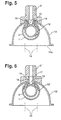
- 5 and 6 is an advantageous embodiment of the new double tube heat exchanger shown in that the double tube heat exchanger there as an oil cooler directly into one the cooler header boxes for the engine coolant are installed.
- a double-tube cooler (12) for this purpose.
- a collecting box (13) not shown - because known - coolant cooler installed for a motor vehicle engine.
- the collecting box (13) is known from its lower end (13a) completed by a tube sheet, not shown, and it therefore takes place along the axes (14) in the tube sheet opening, but also not shown pipes, an inflow of the outer tube (1) of the double tube oil cooler (12) instead.
- the flow of the coolant also penetrates - if suitable Arrangement of the double tube cooler for the inlet or return nozzle the collecting box (13 - the interior of the inner tube (2).
- the outer tube (1) Provide an opening (15) in at least two places and then you have the edge of this hole with usual Middle pulled out like a collar and in the form of the beaded edge (16) flanged around an opening in the collecting box (13).
- a connecting piece (3 ') has then been placed, the same as the flanged edge (16) with the collecting box (13) is soldered tight.
- the collecting box in the exemplary embodiment (13) also made of a solder-plated aluminum, so that it is sufficient for the production, the appropriate flux in the area of the edge (16) and in the area of the seated Bake the connector (3 ') to apply using the Nocolok process a complete tight soldering of the double tube cooler (12) (as also explained in the previous figures is) and the connection between this double tube cooler and the collecting box (13) and its connecting piece (3 ').
- the outer tube (1) is of course except the Opening (15) with the connecting piece (3 ') also another, Assigned in Fig. 5 opening, not shown, which in attached to the collecting box (13) in the same way and with this is soldered so that, as in the examples of FIG. 1 to 4, through the connecting piece (3 ') the oil to be cooled in the space between the outer tube (1) and inner tube (2) supplied and again through the connection piece, not shown can be dissipated.
- the advantage of the embodiment shown in FIG. 5 is that a cooler made entirely of aluminum with can be made available to a double tube oil cooler, on which no other materials are used, so that a easy recycling is possible.
- FIG. 6 shows an embodiment largely similar to that of Fig. 5. The only difference is that here the of the Opening (15) from the outwardly drawn neck (17) of the double tube cooler (12 ') not around the edge of a corresponding opening flanged around in the collecting box (13 '), but in one corresponding recess (18) of the connecting piece (3 '') pressed in is.
- This neck (17) can also be in the groove (19) inside the connection piece (3 '').
- This embodiment also enables the whole Cooler including double tube cooler is made of aluminum, perfect recycling.
- the collecting box (13) can either - as in FIGS. 5 and 6 shown - half-shell-shaped and with an additional Metal base can be soldered or made in one piece a solder-plated tube or two soldered together Half shells to be made.
Landscapes
- Engineering & Computer Science (AREA)
- Physics & Mathematics (AREA)
- Thermal Sciences (AREA)
- Mechanical Engineering (AREA)
- General Engineering & Computer Science (AREA)
- Heat-Exchange Devices With Radiators And Conduit Assemblies (AREA)
- Details Of Heat-Exchange And Heat-Transfer (AREA)
Description
- Fig. 1
- einen Doppelrohrwärmetauscher nach der Erfindung in einer ersten Ausführungsform,
- Fig. 2
- eine vergrößerte Darstellung des linken Endes des Wärmetauschers der Fig. 1,
- Fig. 3
- einen Doppelrohrwärmetauscher nach der Erfindung in einer zweiten Ausführungsform,
- Fig. 4
- eine Detaildarstellung des linken Endes eines Doppelrohrwärmetauscher in einer dritten Variante,
- Fig. 5
- einen in den Sammelkasten eines Kühlers eines Kraftfahrzeugmotors integrierten Doppelrohrkühler nach der Erfindung und
- Fig. 6
- eine Variante eines in einen Sammelkasten nach Fig. 5 eingebauten Doppelrohrkühlers.
Claims (14)
- Doppelrohrwärmetauscher, bestehend aus zwei koaxial ineinandergesetzten Rohren (1, 2) bzw. (1', 2'), insbesondere aus lotplattiertem Aluminium, die an ihren Enden miteinander zur Bildung eines zwischen ihnen liegenden Strömungskanales (6) dicht verbunden sind, wobei in den Strömungskanal gegebenenfalls eine Turbulenzeinlage (8) eingesetzt ist, dadurch gekennzeichnet, daß an beiden Enden der Rohre (1, 2 bzw. 1', 2') mindestens ein von mindestens einem der Rohre abragender umlaufender wulstartiger Bund (9, 10 bzw. 10', 11) vorgesehen ist, dessen Höhe der Differenz der Radien (r1, r2) der Innenwand des äußeren und der Außenwand des inneren Rohres entspricht und daß die Bunde gegebenenfalls mit der Turbulenzeinlage (8) dicht mit der Rohrwand verlötet sind, an der sie anliegen.
- Doppelrohrwärmetauscher nach Anspruch 1, dadurch gekennzeichnet, daß jeder wulstartige Bund (9, 10, 10', 11) aus dem Material des Rohres herausgedrückt ist.
- Doppelrohrwärmetauscher nach Anspruch 2, dadurch gekennzeichnet, daß jeder Bund (9, 10, 10') kurz vor dem Ende des Rohres in der Art einer umlaufenden Sicke herausgedrückt ist.
- Doppelrohrwärmetauscher nach einem der Ansprüche 1 bis 3, dadurch gekennzeichnet, daß jedes Rohr (1 bzw. 2) nur mit einem Wulst (9 bzw. 10') versehen ist.
- Doppelrohrwärmetauscher nach einem der Ansprüche 1 bis 3, dadurch gekennzeichnet, daß ein Rohr (1) glatt, das andere jedoch an seinen beiden Enden mit je einem Wulst (9, 10) ausgebildet ist.
- Doppelrohrwärmetauscher nach Anspruch 1 oder 2, dadurch gekennzeichnet, daß der Bund (11) durch Einrollen des Endes des Rohres (2') hergestellt ist.
- Verfahren zur Herstellung eines Doppelrohrwärmetauschers nach Anspruch 1, dadurch gekennzeichnet, daß mindestens eines der Rohre aus einem lotplattiertem Material besteht, daß an mindestens einem der Rohre im Bereich der Enden aus dem Rohrmaterial herausgedrückte bundartige Wülste gebildet werden, deren Höhe der Differenz der Radien der Innenwand des äußeren und der Außenwand des inneren Rohres entspricht, daß mindestens eines der Rohre vor oder nach dem Herausdrücken der Wülste oder gegebenenfalls die ebenfalls lotplattierte Turbulenzeinlage (8) mit einem Hartlöt-Flußmittel versehen wird, dann die beiden Rohre übereinandergeschoben und durch die Wülste auf Abstand gehalten werden und daß die so aneinandergehaltenen Rohre zum Zweck des Verlötens erhitzt werden.
- Doppelrohrwärmetauscher nach Anspruch 7, dadurch gekennzeichnet, daß als Ausgangsmaterial für die Rohre Aluminium-Bleche mit ein- oder beidseitig aufplattierten Zusatzwerkstoffen mit einem Siliziumgehalt zwischen 7,5% bis 12,5% vorgesehen sind, die zu einer Rohrform verschweißt werden.
- Doppelrohrwärmetauscher nach Anspruch 7, dadurch gekennzeichnet, daß als Flußmittel ein handelsübliches Nocolok-Flußmittel verwendet wird.
- Doppelrohrwärmetauscher nach einem der Ansprüche 1 bis 6, gekennzeichnet durch mindestens eine Zu- oder Abflußöffnung (15), mit einem um diese herum aus dem Material nach außen gedrückten Hals (16, 17), der in eine Öffnung eines Sammelkasten (13) eines Motorkühlers eingeschoben und mit diesem dicht verlötet ist.
- Doppelrohrwärmetauscher nach Anspruch 10, dadurch gekennzeichnet, daß der Hals (16) um den Rand der Öffnung im Sammelkasten (13) umgebördelt ist und von einem Anschlußstutzen (3') umgeben ist.
- Doppelrohrwärmetauscher nach Anspruch 10, dadurch gekennzeichnet, daß der Hals (17) in eine entsprechende Ausnehmung (18, 19) eines Anschlußstutzens (3'') hereingedrückt und darin verlötet ist.
- Doppelrohrwärmetauscher nach einem der Ansprüche 10 bis 12, dadurch gekennzeichnet, daß als Material für die Herstellung des Sammelkastens lotplattiertes Aluminium verwendet ist.
- Doppelrohrwärmetauscher nach Anspruch 10, dadurch gekennzeichnet, daß der Anschlußstutzen (3', 3'') aus Aluminium besteht und in einem Arbeitsgang im Nocolok-Verfahren mit dem Sammelkasten und dem Doppelrohrwärmetauscher verlötet ist.
Applications Claiming Priority (2)
| Application Number | Priority Date | Filing Date | Title |
|---|---|---|---|
| DE19509788 | 1995-03-17 | ||
| DE19509788A DE19509788A1 (de) | 1995-03-17 | 1995-03-17 | Doppelrohrwärmetauscher und Verfahren zu seiner Herstellung |
Publications (3)
| Publication Number | Publication Date |
|---|---|
| EP0732560A2 EP0732560A2 (de) | 1996-09-18 |
| EP0732560A3 EP0732560A3 (de) | 1997-10-29 |
| EP0732560B1 true EP0732560B1 (de) | 2001-05-23 |
Family
ID=7757004
Family Applications (1)
| Application Number | Title | Priority Date | Filing Date |
|---|---|---|---|
| EP96103446A Expired - Lifetime EP0732560B1 (de) | 1995-03-17 | 1996-03-06 | Doppelrohrwärmetauscher und Verfahren zu seiner Herstellung |
Country Status (3)
| Country | Link |
|---|---|
| US (1) | US5732769A (de) |
| EP (1) | EP0732560B1 (de) |
| DE (2) | DE19509788A1 (de) |
Families Citing this family (24)
| Publication number | Priority date | Publication date | Assignee | Title |
|---|---|---|---|---|
| EP0840081B1 (de) * | 1996-10-29 | 2003-04-16 | Denso Corporation | Wärmetauscher und Verfahren zu dessen Herstellung |
| DE69713724T2 (de) * | 1996-12-03 | 2002-11-14 | Calsonic Kansei Corp., Tokio/Tokyo | Befestigungsvorrichtung für Ölkühler und Verfahren zur Befestigung eines Ölkühlers |
| US5967111A (en) * | 1998-03-24 | 1999-10-19 | Purolator Products Company | Arrangement in an oil filter with integral oil cooler |
| DE19820412A1 (de) * | 1998-05-07 | 1999-11-11 | Behr Gmbh & Co | Wärmeübertrageranordnung für ein Kraftfahrzeug |
| US6746600B2 (en) * | 2001-10-31 | 2004-06-08 | Arvin Technologies, Inc. | Fluid filter with integrated cooler |
| US20040089439A1 (en) * | 2002-11-07 | 2004-05-13 | Treverton Andrew Clare | Tube-to-tube heat exchanger assembly |
| JP3794392B2 (ja) * | 2003-02-25 | 2006-07-05 | 日産自動車株式会社 | 電気自動車の駆動ユニット |
| US20050155748A1 (en) * | 2003-08-29 | 2005-07-21 | Dana Canada Corporation | Concentric tube heat exchanger end seal therefor |
| CA2439023C (en) * | 2003-08-29 | 2011-12-06 | Dana Canada Corporation | Concentric tube heat exchanger and end seal therefor |
| DE10347676A1 (de) * | 2003-10-09 | 2005-05-04 | Behr Gmbh & Co Kg | Heizungskreislauf für ein Kraftfahrzeug |
| US7191824B2 (en) * | 2003-11-21 | 2007-03-20 | Dana Canada Corporation | Tubular charge air cooler |
| DE102004037392A1 (de) * | 2004-07-30 | 2006-03-23 | Behr Gmbh & Co. Kg | Verfahren zum Löten eines Wärmeübertragers und Wärmeübertrager, hergestellt nach dem Verfahren |
| KR100721459B1 (ko) * | 2005-11-19 | 2007-05-25 | 주식회사 경동에버런 | 난방 및 온수겸용 순간식 보일러의 이중관 열교환기 및보일러 |
| KR100641277B1 (ko) * | 2005-11-22 | 2006-11-02 | 주식회사 경동에버런 | 난방 및 온수겸용 보일러의 이중관 열교환기 |
| JP4864439B2 (ja) * | 2005-12-06 | 2012-02-01 | 株式会社デンソー | 二重管、およびその製造方法 |
| DE102007027639A1 (de) * | 2007-06-15 | 2008-12-18 | Rolls-Royce Deutschland Ltd & Co Kg | Wärmetauscher für eine Fluggasturbine |
| DE102009028455A1 (de) * | 2009-08-11 | 2011-02-17 | Ford Global Technologies, LLC, Dearborn | Kühlmittelumströmte Ölleitung |
| US9052146B2 (en) | 2010-12-06 | 2015-06-09 | Saudi Arabian Oil Company | Combined cooling of lube/seal oil and sample coolers |
| DE102011008119A1 (de) | 2011-01-07 | 2012-07-12 | Arup Alu-Rohr Und -Profil Gmbh | Doppelrohr, sowie Doppelrohr-Wärmetauscher |
| US20120222849A1 (en) * | 2011-03-02 | 2012-09-06 | Yen-Ti Liu | Oil-Cooling Tube |
| GB201513415D0 (en) * | 2015-07-30 | 2015-09-16 | Senior Uk Ltd | Finned coaxial cooler |
| JP7169923B2 (ja) * | 2019-03-27 | 2022-11-11 | 日本碍子株式会社 | 熱交換器 |
| CN111750705B (zh) * | 2019-03-28 | 2022-04-29 | 日本碍子株式会社 | 热交换器的流路结构以及热交换器 |
| US11835301B2 (en) | 2021-04-07 | 2023-12-05 | Ecoinnovation Technologies Incorporée | Modular heat exchanger and method of assembly thereof |
Family Cites Families (20)
| Publication number | Priority date | Publication date | Assignee | Title |
|---|---|---|---|---|
| US2752128A (en) * | 1955-10-17 | 1956-06-26 | Modine Mfg Co | Heat exchange structure |
| US3001767A (en) * | 1959-11-16 | 1961-09-26 | Kenmore Machine Products Inc | Tubular structure |
| GB977579A (en) * | 1962-03-01 | 1964-12-09 | Serck Radiators Ltd | Heat exchanger |
| US3323586A (en) * | 1964-10-14 | 1967-06-06 | Olin Mathieson | Concentric tube heat exchanger with sintered metal matrix |
| US3339260A (en) * | 1964-11-25 | 1967-09-05 | Olin Mathieson | Method of producing heat exchangers |
| US3831672A (en) * | 1971-04-05 | 1974-08-27 | Ford Motor Co | Liquid-to-liquid heat exchanger |
| US3831671A (en) * | 1972-02-28 | 1974-08-27 | Ford Motor Co | Transmission fluid heat exchanger in a motor vehicle cooling system |
| FR2306421A1 (fr) * | 1975-04-02 | 1976-10-29 | Ferodo Sa | Perfectionnements aux appareils de refroidissement de liquides |
| CA1094544A (en) * | 1978-02-03 | 1981-01-27 | William Melnyk | Heat exchanger |
| CA1123423A (en) * | 1979-08-03 | 1982-05-11 | Modine Manufacturing Company | Heat exchanger and method of making |
| DE3133756C2 (de) * | 1980-10-10 | 1985-04-25 | Süddeutsche Kühlerfabrik Julius Fr. Behr GmbH & Co KG, 7000 Stuttgart | Doppelrohrkühler |
| US4373578A (en) * | 1981-04-23 | 1983-02-15 | Modine Manufacturing Company | Radiator with heat exchanger |
| JPS6137395A (ja) * | 1984-07-31 | 1986-02-22 | Sumitomo Light Metal Ind Ltd | アルミニウム製熱交換器用アルミニウム合金ろう |
| FR2592147B1 (fr) * | 1985-12-23 | 1988-03-18 | Stein Industrie | Dispositif de controle de debit dans un tube d'echangeur de chaleur. |
| DE3602891A1 (de) * | 1986-01-31 | 1987-08-06 | Sueddeutsche Kuehler Behr | Waermetauscher fuer kraftfahrzeuge |
| DE3912534C2 (de) * | 1989-04-17 | 1994-07-14 | Hansa Metallwerke Ag | Benzinkühler |
| US5107922A (en) * | 1991-03-01 | 1992-04-28 | Long Manufacturing Ltd. | Optimized offset strip fin for use in contact heat exchangers |
| SE505252C2 (sv) * | 1992-12-15 | 1997-07-21 | Valeo Engine Cooling Ab | Oljekylare |
| DE4330214B4 (de) * | 1993-09-07 | 2005-02-17 | Behr Gmbh & Co. Kg | Wärmetauscher |
| DE9318913U1 (de) * | 1993-12-09 | 1994-02-10 | Behr Gmbh & Co, 70469 Stuttgart | Doppelrohrwärmetauscher mit Innenabstützung |
-
1995
- 1995-03-17 DE DE19509788A patent/DE19509788A1/de not_active Withdrawn
-
1996
- 1996-03-05 US US08/610,937 patent/US5732769A/en not_active Expired - Fee Related
- 1996-03-06 DE DE59606931T patent/DE59606931D1/de not_active Expired - Fee Related
- 1996-03-06 EP EP96103446A patent/EP0732560B1/de not_active Expired - Lifetime
Also Published As
| Publication number | Publication date |
|---|---|
| US5732769A (en) | 1998-03-31 |
| DE19509788A1 (de) | 1996-09-19 |
| DE59606931D1 (de) | 2001-06-28 |
| EP0732560A3 (de) | 1997-10-29 |
| EP0732560A2 (de) | 1996-09-18 |
Similar Documents
| Publication | Publication Date | Title |
|---|---|---|
| EP0732560B1 (de) | Doppelrohrwärmetauscher und Verfahren zu seiner Herstellung | |
| EP0775884B1 (de) | Wärmetauscher und ein Verfahren zur Herstellung eines Wärmetauschers | |
| DE3788681T2 (de) | Ansaugkrümmer und Verfahren zu seiner Herstellung. | |
| EP1281923B1 (de) | Flachrohr für Wärmetauscher und Herstellungsverfahren | |
| DE19848744B4 (de) | Gelöteter Kondensator für eine Klimaanlage | |
| EP1929231B1 (de) | Wärmeübertrager, insbesondere abgaswärmeübertrager für kraftfahrzeuge | |
| EP0660064B1 (de) | Wärmetauscher | |
| DE2831832A1 (de) | Verfahren zur herstellung einer verbindung zwischen zwei rohren, verfahren zur herstellung eines waermeaustauschers, rohrverbindung sowie waermeaustauscher | |
| DE69600309T2 (de) | Flachrohr für einen wärmetauscher | |
| DE69203387T2 (de) | Wärmeaustauscher mit rohrförmigen Endkammern mit Querwänden und Methode zu seiner Herstellung. | |
| DE19510283A1 (de) | Flachrohr für einen verlöteten Wärmetauscher und Verfahren zu seiner Herstellung | |
| EP0781623B1 (de) | Verfahren zur Herstellung von hartgelöteten Aluminiumwärmetauschern | |
| DE10228246A1 (de) | Abgaswärmeübertrager und Verfahren zu seiner Herstellung | |
| DE3133756C2 (de) | Doppelrohrkühler | |
| DE69617598T2 (de) | Wärmetauscher, insbesondere Ladeluftkühler für Kraftfahrzeug | |
| EP1139052A2 (de) | Kühler für Kraftfahrzeuge sowie Herstellungsverfahren | |
| EP0992757A2 (de) | Sammelrohreinheit für einen Wärmeübertrager | |
| DE69310966T2 (de) | Herstellungsverfahren für eine Rohrverbindung | |
| DE102011008119A1 (de) | Doppelrohr, sowie Doppelrohr-Wärmetauscher | |
| EP2297537B1 (de) | Wärmeübertrager, insbesondere wärmeübertager eines kraftfahrzeuges, und verfahren zum herstellen eines kühlrohres eines wärmeübertragers | |
| DE69703856T2 (de) | Kupplung für zwei Metallrohre | |
| DE10016113A1 (de) | Kühler für Kraftfahrzeuge und Herstellungsverfahren | |
| DE19546917A1 (de) | Wärmetauscher mit zusammengesteckten Rohrelementen, insbesondere für Kraftfahrzeuge, und Herstellungsverfahren | |
| DE102015201808A1 (de) | Wärmetauscherrohranordnung und Verfahren zum Herstellen derselben | |
| DE4402020C2 (de) | Verfahren und Anlage zur Herstellung von Wärmetauschern für fluide Wärmeträger sowie druckfester Wärmetausch |
Legal Events
| Date | Code | Title | Description |
|---|---|---|---|
| PUAI | Public reference made under article 153(3) epc to a published international application that has entered the european phase |
Free format text: ORIGINAL CODE: 0009012 |
|
| AK | Designated contracting states |
Kind code of ref document: A2 Designated state(s): DE ES FR GB SE |
|
| PUAL | Search report despatched |
Free format text: ORIGINAL CODE: 0009013 |
|
| AK | Designated contracting states |
Kind code of ref document: A3 Designated state(s): DE ES FR GB SE |
|
| 17P | Request for examination filed |
Effective date: 19980408 |
|
| GRAG | Despatch of communication of intention to grant |
Free format text: ORIGINAL CODE: EPIDOS AGRA |
|
| 17Q | First examination report despatched |
Effective date: 20000811 |
|
| GRAG | Despatch of communication of intention to grant |
Free format text: ORIGINAL CODE: EPIDOS AGRA |
|
| GRAH | Despatch of communication of intention to grant a patent |
Free format text: ORIGINAL CODE: EPIDOS IGRA |
|
| GRAH | Despatch of communication of intention to grant a patent |
Free format text: ORIGINAL CODE: EPIDOS IGRA |
|
| GRAA | (expected) grant |
Free format text: ORIGINAL CODE: 0009210 |
|
| AK | Designated contracting states |
Kind code of ref document: B1 Designated state(s): DE ES FR GB SE |
|
| PG25 | Lapsed in a contracting state [announced via postgrant information from national office to epo] |
Ref country code: GB Free format text: LAPSE BECAUSE OF FAILURE TO SUBMIT A TRANSLATION OF THE DESCRIPTION OR TO PAY THE FEE WITHIN THE PRESCRIBED TIME-LIMIT Effective date: 20010523 Ref country code: FR Free format text: LAPSE BECAUSE OF FAILURE TO SUBMIT A TRANSLATION OF THE DESCRIPTION OR TO PAY THE FEE WITHIN THE PRESCRIBED TIME-LIMIT Effective date: 20010523 |
|
| REF | Corresponds to: |
Ref document number: 59606931 Country of ref document: DE Date of ref document: 20010628 |
|
| PG25 | Lapsed in a contracting state [announced via postgrant information from national office to epo] |
Ref country code: SE Free format text: LAPSE BECAUSE OF FAILURE TO SUBMIT A TRANSLATION OF THE DESCRIPTION OR TO PAY THE FEE WITHIN THE PRESCRIBED TIME-LIMIT Effective date: 20010823 |
|
| GBV | Gb: ep patent (uk) treated as always having been void in accordance with gb section 77(7)/1977 [no translation filed] |
Effective date: 20010523 |
|
| PG25 | Lapsed in a contracting state [announced via postgrant information from national office to epo] |
Ref country code: ES Free format text: LAPSE BECAUSE OF FAILURE TO SUBMIT A TRANSLATION OF THE DESCRIPTION OR TO PAY THE FEE WITHIN THE PRESCRIBED TIME-LIMIT Effective date: 20011130 |
|
| EN | Fr: translation not filed | ||
| PLBE | No opposition filed within time limit |
Free format text: ORIGINAL CODE: 0009261 |
|
| STAA | Information on the status of an ep patent application or granted ep patent |
Free format text: STATUS: NO OPPOSITION FILED WITHIN TIME LIMIT |
|
| 26N | No opposition filed | ||
| PGFP | Annual fee paid to national office [announced via postgrant information from national office to epo] |
Ref country code: DE Payment date: 20080415 Year of fee payment: 13 |
|
| PG25 | Lapsed in a contracting state [announced via postgrant information from national office to epo] |
Ref country code: DE Free format text: LAPSE BECAUSE OF NON-PAYMENT OF DUE FEES Effective date: 20091001 |