EP0731468B1 - Videodatenaufzeichnung und -wiedergabe - Google Patents
Videodatenaufzeichnung und -wiedergabe Download PDFInfo
- Publication number
- EP0731468B1 EP0731468B1 EP96301466A EP96301466A EP0731468B1 EP 0731468 B1 EP0731468 B1 EP 0731468B1 EP 96301466 A EP96301466 A EP 96301466A EP 96301466 A EP96301466 A EP 96301466A EP 0731468 B1 EP0731468 B1 EP 0731468B1
- Authority
- EP
- European Patent Office
- Prior art keywords
- data
- blocks
- video
- sub
- transmission
- Prior art date
- Legal status (The legal status is an assumption and is not a legal conclusion. Google has not performed a legal analysis and makes no representation as to the accuracy of the status listed.)
- Expired - Lifetime
Links
- 230000005540 biological transmission Effects 0.000 claims description 103
- 238000006243 chemical reaction Methods 0.000 claims description 65
- 238000000034 method Methods 0.000 claims description 30
- 230000006835 compression Effects 0.000 claims description 7
- 238000007906 compression Methods 0.000 claims description 7
- 230000003287 optical effect Effects 0.000 claims description 6
- 239000000872 buffer Substances 0.000 description 12
- 238000010586 diagram Methods 0.000 description 2
- 230000003139 buffering effect Effects 0.000 description 1
- 230000000694 effects Effects 0.000 description 1
Images


Classifications
-
- H—ELECTRICITY
- H04—ELECTRIC COMMUNICATION TECHNIQUE
- H04N—PICTORIAL COMMUNICATION, e.g. TELEVISION
- H04N7/00—Television systems
- H04N7/16—Analogue secrecy systems; Analogue subscription systems
- H04N7/173—Analogue secrecy systems; Analogue subscription systems with two-way working, e.g. subscriber sending a programme selection signal
- H04N7/17309—Transmission or handling of upstream communications
- H04N7/17336—Handling of requests in head-ends
-
- G—PHYSICS
- G11—INFORMATION STORAGE
- G11B—INFORMATION STORAGE BASED ON RELATIVE MOVEMENT BETWEEN RECORD CARRIER AND TRANSDUCER
- G11B27/00—Editing; Indexing; Addressing; Timing or synchronising; Monitoring; Measuring tape travel
- G11B27/02—Editing, e.g. varying the order of information signals recorded on, or reproduced from, record carriers
- G11B27/031—Electronic editing of digitised analogue information signals, e.g. audio or video signals
- G11B27/034—Electronic editing of digitised analogue information signals, e.g. audio or video signals on discs
-
- G—PHYSICS
- G11—INFORMATION STORAGE
- G11B—INFORMATION STORAGE BASED ON RELATIVE MOVEMENT BETWEEN RECORD CARRIER AND TRANSDUCER
- G11B27/00—Editing; Indexing; Addressing; Timing or synchronising; Monitoring; Measuring tape travel
- G11B27/10—Indexing; Addressing; Timing or synchronising; Measuring tape travel
- G11B27/102—Programmed access in sequence to addressed parts of tracks of operating record carriers
- G11B27/105—Programmed access in sequence to addressed parts of tracks of operating record carriers of operating discs
-
- G—PHYSICS
- G11—INFORMATION STORAGE
- G11B—INFORMATION STORAGE BASED ON RELATIVE MOVEMENT BETWEEN RECORD CARRIER AND TRANSDUCER
- G11B2220/00—Record carriers by type
- G11B2220/20—Disc-shaped record carriers
-
- G—PHYSICS
- G11—INFORMATION STORAGE
- G11B—INFORMATION STORAGE BASED ON RELATIVE MOVEMENT BETWEEN RECORD CARRIER AND TRANSDUCER
- G11B2220/00—Record carriers by type
- G11B2220/20—Disc-shaped record carriers
- G11B2220/25—Disc-shaped record carriers characterised in that the disc is based on a specific recording technology
- G11B2220/2525—Magneto-optical [MO] discs
-
- G—PHYSICS
- G11—INFORMATION STORAGE
- G11B—INFORMATION STORAGE BASED ON RELATIVE MOVEMENT BETWEEN RECORD CARRIER AND TRANSDUCER
- G11B2220/00—Record carriers by type
- G11B2220/90—Tape-like record carriers
Definitions
- This invention relates to video data recording and reproducing.
- Embodiments of the invention described hereinbelow provide a video data recording apparatus and a video data reproducing apparatus for an NVOD (near video on demand) system.
- NVOD near video on demand
- a near video on demand (NVOD) system has been recently suggested.
- the near video on demand system produces a plurality of audio data and video data, described as AV data below, having a predetermined time interval from each other from AV data and transmits the produced AV data or analog AV signals converted from the produced AV data to viewers via a plurality of communication lines of a cable television (CATV) system etc. respectively.
- CATV cable television
- the AV data is reproduced from a recording medium such as a magnetic optical disc (MO disc) and a plurality of AV data for NVOD, described as NVOD data below, are produced by shifting the AV data by predetermined time intervals.
- a recording medium such as a magnetic optical disc (MO disc)
- NVOD data a plurality of AV data for NVOD, described as NVOD data below
- NVOD data reproducing apparatus every time an NVOD system is to transmit new NVOD data, data indicating a time length of the original AV data of the new NVOD data, a data rate of the new NVOD data, an arrangement of the new NVOD data on the MO disc, a number of the new NVOD data, that is, a number of communication lines needed for provision of the new NVOD data per subscriber (transmission channels) respectively, etc. must be set in an apparatus for NVOD data transmission (NVOD data reproducing apparatus) by the operator of the NVOD system.
- European patent serial number EP 0 609 054 A2 discloses a recording and reproducing apparatus for NVOD which is arranged to provide on a plurality of channels the same video data.
- the recording and reproducing apparatus has an arrangement for providing the video data on the plurality of channels, in which the video data is divided into the same number of blocks of data as the number of channels and each block is divided into a predetermined number of sub-blocks of data which are stored on a recording medium.
- a video data recording apparatus comprising an input means for inputting a number of channels, said number of channels indicating a plurality of channels on which a plurality of series of video data are transmitted, said plurality of series of video data being identical to an original series of data and having a predetermined time difference; a division means for dividing said digital video data into the same number of blocks of data as the number of said plurality of transmission channels and dividing said blocks of data into a predetermined number of sub-blocks of data; characterised by an arrangement conversion means for converting the arrangement of said sub-blocks of data divided by the division means into another arrangement of sub-blocks of data in accordance with a predetermined sequence; and a recording means for recording the converted arrangement of said sub-blocks of data from the arrangement conversion means in a conversion data area of a recording medium and data indicating the number of channels in a control data area of said recording medium.
- the apparatus comprises a compression means for compressing said original series of video data to reduce a data rate of said original series of video data to a designated data rate and providing the compressed video data to the division means, the input means inputting data indicating said designated data rate.
- said recording means records said data indicating said designated data rate to said recording medium.
- said recording medium comprises a magnetic optical disc.
- a video reproducing apparatus comprising a reproducing means for reproducing from a conversion data area of a recording medium sub-blocks of data arranged into a predetermined arrangement and from a control data area data indicating a number of a plurality of transmission channels for providing a plurality of series of transmission video data having a predetermined time interval from each other generated from video data for said plurality of transmission channels; a plurality of storage means for storing said sub-blocks of data reproduced by the reproducing means; a distribution means for distributing said sub-blocks of data to said plurality of storage means according to said data indicating the number of said plurality of transmission channels; and a restoring means for restoring said sub-blocks of data stored in said plurality of storage means and outputting said restored sub-blocks of data as said plurality of series of transmission video data for said plurality of transmission channels.
- said reproducing means reproduces the data indicating said designated data rate from said recording medium and said restoring means restores said sub-blocks of data at an equal data rate indicated by the reproduced data.
- the reproducing means comprises a plurality of expansion means for expanding said sub-blocks of data restored from said plurality of storage means.
- said recording medium comprises a magnetic optical disc.
- a video data recording method comprising a step of inputting a number of a plurality of transmission channels for transmitting a plurality of series of transmission video data having a predetermined time interval from each other generated from an original series of video data for said plurality of transmission channels; a step of dividing said original series of video data into the same number of blocks of data as the number of said plurality of transmission channels and said blocks of data into a predetermined number of sub-blocks of data; a step of arranging the divided sub-blocks of data into a predetermined arrangement; and a step of recording said sub-blocks of data arranged into the predetermined arrangement in a conversion data area of a recording medium and data indicating the number of said plurality of transmission channels in a control data area of said recording medium.
- a video data reproducing method comprising a step of reproducing from a conversion data area of a recording medium sub-blocks of data arranged into a predetermined arrangement and from a control data area data indicating a number of a plurality of transmission channels for transmitting a plurality of series of transmission video data having a predetermined time interval from each other for said plurality of transmission channels; a step of distributing said sub-blocks of data reproduced to a plurality of storage means according to said data indicating the number of said plurality of transmission channels; and a step of restoring said sub-blocks of data stored in said plurality of storage means and outputting the restored sub-blocks of data as series of transmission video data for said transmission channels.
- the NVOD data recording apparatus 2 is constituted by a video tape recording apparatus (VTR apparatus) 20, an encoding device 21, an arrangement conversion circuit 22, a selector circuit (SEL) 24, a magneto-optic disc apparatus (MOD) 26, a control circuit 28, and a terminal device 30, converts an arrangement of digital audio data and video data (AV data) reproduced from a video tape 32 by the VTR apparatus 20 into a predetermined arrangement suitable for generation of the NVOD data to generate digital converted data S22, and records the converted data S22 with digital control data S28 used for the generation of the NVOD data.
- VTR apparatus video tape recording apparatus
- SEL selector circuit
- MOD magneto-optic disc apparatus
- the control circuit 28 controls those structural elements of the NVOD data recording apparatus 2 according to handling data input by an operator of the NVOD data recording apparatus 2 and, further, generates the control data S28 to be recorded to a control data area on a magneto-optic disc (MO disc) 10 and outputs the generated control data to the selector circuit 24.
- the handling data input from the terminal device 30 are data indicating the start and the end of the operation to the NVOD data recording apparatus 2, data recorded to the control area on the MO disc 10, etc., for example.
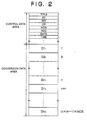
- the control data area on the MO disc 10 will be explained with reference to Fig.2.
- the VTR apparatus 20 reproduces digital AV data from the video tape 32 according to control via a control signal C20 by the control circuit 28 to provide the reproduced AV data to the encoding device 21 as AV data S20.
- the encoding device 21 compresses and codes the input AV data S20 by a predetermined compression and coding method such as MPEG (motion picture experts group) to provide compressed and coded AV data to the arrangement conversion circuit 22 as AV data S21.
- a predetermined compression and coding method such as MPEG (motion picture experts group) to provide compressed and coded AV data to the arrangement conversion circuit 22 as AV data S21.
- the compression and coding operation of the encoding device 21 described above is controlled via a control signal C21 indicating a data rate of the AV data S21 by the control circuit 28.
- the arrangement conversion circuit 22 converts an arrangement of the AV data S21 into an arrangement suitable for the generation of the NVOD data according to the control via control signal C22 by the control circuit 28 and outputs the same as conversion data S22 to the selector circuit 24.
- the process for converting the AV data S21 to the conversion data S22 will be explained below.
- the arrangement conversion circuit 22 divides these series of AV data S21-1, S21-2,..., and S21-n into m (division number; m is an integer) sub-blocks of data to generate the AV data D1-1, D1-2,..., D1-m, D2-1, D2-2,.., D2-m,..., Dn-1,Dn-2,... and Dn-m.
- the arrangement conversion circuit 22 converts the arrangement of these AV data D1-1, D1-2,..., D1-m, D2-1, D2-2,.., D2-m,..., Dn-1,Dn-2,... and Dn-m into an arrangement such as AV data D1-1, D2-1,..., Dn-1, D1-2, D2-2,.., Dn-2,..., D1-m,D2-m,... and Dn-m to generate the AV data S21-1, S21-2,... and S21-m and outputs the resultant data as the conversion data S22.
- the division number m is determined according to the storage capacity of a FIFO in an NVOD data transmission apparatus 1.
- the data length of the series of AV data S21 is [S21]
- the conversion data S22 is recorded to the conversion data area on the MO disc 10 respectively, as explained below with reference to Fig. 2.
- the NVOD data transmission apparatus 1 will be explained later with reference to Fig. 5.
- the selector circuit 24 selects the conversion data S22 or the control data S28 and outputs the selected data to the MOD 26 as the selected data S24. That is, the control circuit 28 outputs the control data S28 to the selector circuit 24 and controls the selector circuit 24 to select the same to record to the control data area on the MO disc 10, and the control circuit 28 controls the arrangement conversion circuit 22 to output the conversion data S22 to the selector circuit 24 and controls the selector circuit 24 to select the same to record to the conversion data area on the MO disc 10.
- the MOD 26 records the selected data S24 input from the selector circuit 24 to the MO disc 10 according to the control via the control signal C26 by the control circuit 28.
- the MO disc 10 is divided into the control data area and the conversion data area.
- data needed for the process of generation of the NVOD data in the NVOD data transmission apparatus 1 data used for the automatic operation of the NVOD data transmission apparatus 1, data used to improve the ease of operation of the NVOD data transmission apparatus 1. etc. are recorded.
- data needed for the process of generation of the NVOD data in the NVOD data transmission apparatus 1 number of sector data (NOS) indicating the number of sectors needed for the recording of AV data D1-1, D1-2,...
- DR data rate data
- DATE date data
- TIME time data
- RIT reproducing interval time data
- the conversion data S22 generated by the arrangement conversion circuit 22 is recorded in the arrangement after conversion.
- the AV data D1-1, D1-2,... and Dn-m included in the conversion data S22 are recorded to continuous NOS sectors of the conversion data area on the MO disc 10.
- the plurality of AV data D1-1, D1-2,... and Dn-m are recorded to different sectors relatively and different sub-blocks of data are not recorded in the same sector. That is, for example, the AV data D1-1 is recorded from the first sector to the (NOS)th sector of the conversion data area, and the AV data D2-1 is recorded from the (NOS+1)th sector to the (2xNOS)th sector of the conversion data area. In this way, even if there is a free area in the (NOS)th sector, the end of the AV data D1-1 and the start of the AV data D2-1 are not recorded in the (NOS)th sector in a mixed state.
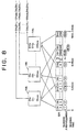
- Figure 3 shows the relation between the AV data S21 before the conversion by the arrangement conversion circuit 22 and the AV data S21 after the conversion by the arrangement conversion circuit 22.
- the AV data S21 before the conversion is divided into 12 blocks of data, i.e., AV data D1, D2,... and D12.
- the time length of every divided block of data is 10 minutes.
- the sub-blocks of data, divided as above, are described below as sub-blocks D1-0, D1-1, D1-2,..., D1-2,399, D2-0, D2-1, D2-2,..., D2-2,399,..., D12-0, D12-1, D12-2,..., D12-2,399. Note that, the sub-block numbers are started from zero in the figures.
- the arrangement of the AV data S21 is converted as shown in Fig. 3. That is, these sub-blocks of data are converted into an arrangement to gather the sub-blocks of data with the identical sub-block numbers.
- the arrangement of the sub-blocks of data becomes sub-blocks D1-0, D2-0, D3-0,..., D12-0, D1-1, D2-1, D3-1,..., D12-1,..., D1-2,399, D2-2,399, D3-2,399,..., D12-2,399 as shown in Fig. 3.
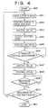
- Figure 4 is a flow chart showing an example of the operation of the control circuit 28 of the NVOD data recording apparatus 2.
- step 400 the control circuit 28 starts the operation.
- the control circuit 28 receives the handling data input by an operator of the NVOD data recording apparatus 2 via the terminal device 30.
- the handling data for example, mention may be made of data such as the title of the AV data going to be recorded on the MO disc 10, reproducing time indicating a time length of the AV data, reproducing time interval indicating the time interval between the NVOD data for the transmission channels, data rate indicating a data rate of the AV data after the compression and coding process, number of sectors indicating the number of sectors needed for the recording of the AV data, number of transmission channels, and date and time indicating the start time of transmission of the NVOD data.
- the control circuit 28 supplies the control signal C21 indicating a data rate of the AV data after the compression and coding process to the encoding device 21. Further, the control circuit 28 supplies the control signal C22 including the data of the reproducing time of the AV data and the number of the transmission channels used for parameters of the arrangement conversion process to the arrangement conversion circuit 22.
- control circuit 28 controls the selector circuit 24 to select the control data S28 from the control circuit 28.
- control circuit 28 supplies the control data S28 including the data shown in Fig. 2, i.e., the title data TITLE, reproducing time data RT, the data rate data DR, the number of sector data NOS, the number of transmission channel data NOC, the date data DATE, and the time data TIME.
- control circuit 28 sets the MOD 26 to the recording operation state to record the control data on the MO disc 10.
- step 406 the control circuit 28 determines whether the recording operation of the MOD 26 to record the control data S28 to the control data area on the MO disc 10 has ended or not.
- the control circuit 28 proceeds to the operation of the next step (S407).
- the determination at step 406 is performed when the MOD 26 finishes recording the control data S28 to a predetermined number of sectors.
- control circuit 28 controls the selector circuit 24 to select the conversion data S22 from the arrangement conversion circuit 22 via the control signal C24.
- the control circuit 28 controls the operation of the VTR apparatus 20 to start the reproducing of the AV data S20 from the video tape 32.
- the VTR apparatus 20 starts to reproduce the AV data S20 from the video tape 32 and provides the same to the encoding device 21, and the encoding device 21 compresses the amount of data and codes the AV data S20 to fit the data rate of the AV data S21 to the data rate indicated via the control signal C21 by the control circuit 28.
- the AV data S20 compressed and coded by the encoding device 21 is provided to the arrangement conversion circuit 22 as the AV data S21.
- the arrangement of the AV data S21 is subjected to conversion by the arrangement conversion circuit 22, and the AV data S21 is divided into sub-blocks of data and converted into the arrangement shown in Fig. 3.
- the AV data S22 converted in arrangement thereof by the arrangement conversion circuit 22 is supplied to the selector circuit 24 and is selected by the selector circuit 24 to be supplied to the MOD 26 as the AV data S24.
- the MOD 26 records the supplied AV data to the conversion data area on the MO disc 10.
- the control circuit 28 determines whether the recording of the AV data of a video program reproduced by the MOD 26 from the MO disc 10 has finished or not.
- the determination at step 409 is performed by the control circuit 28 comparing the number of the sectors of the MO disc 10 needed for the recording of the entire AV data S21 of a video program and the number of the sectors to which the AV data S21 of a video program is actually recorded.
- the number of the sectors of the MO disc 10 needed for the recording of the entire AV data S21 of a video program can be calculated from the volume of the entire AV data S21 of a video program after compression and coding by the encoding device 21 and the volume of data to be recorded to a sector of the MO disc 10.
- step 410 the control circuit 28 determines whether the recording of the AV data S21 of all of the footage, i.e., the AV data S21 of all the plurality of video programs, has finished or not.
- the AV data of these video programs are recorded to individual video tapes 32.
- These AV data of the video programs are reproduced from the individual video tapes 32, are subjected to the process of the structural elements of the NVOD data recording apparatus 2, and are recorded to individual MO discs 10 respectively.
- the control circuit 28 proceeds to the process of the step 401 before the recording of the whole footage of all of the video programs ends. Otherwise, when the recording of the whole footage of all of the video programs ends, the control circuit 28 proceeds to the process of step 411 to end the operation.
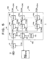
- the NVOD data transmission apparatus 1 is constituted by an magnetic optical disc apparatus (MOD) 12 and an NVOD data generation apparatus 14 and is connected with a host computer 15.
- the NVOD data generation apparatus 14 is constituted by a SCSI (small computer system interface) interface circuit (SCSI) 140 (described as SCSI IF 140 below) and a plurality of NVOD data generation units 150-1, 150-2,..., and 150-n and a control device 152.
- SCSI small computer system interface interface circuit
- the NVOD data generation units 150-1, 150-2,..., and 150-n are constituted by FIFO memory circuits (FIFO) 146-1, 146-2,..., and 146-n and decoding devices 148-1, 148-2, ..., and 148-n (DEC) respectively.
- FIFO FIFO memory circuits
- the control device 152 is constituted by a control circuit 142 comprising a CPU and a memory circuit 144 comprising RAM's.
- the NVOD data transmission apparatus 1 reproduces the control data and the conversion data recorded to the MO disc 10 as shown in Fig. 2, generates NVOD data S146-1, S146-2, ..., and S146-n according to the reproduced control data, and decodes and expands the generated NVOD data to transmit audio and video signals (AV signals) S148-1, S148-2,..., and S148-n to communication lines (transmission channels) CH1, CH2,..., and CHn.
- AV signals audio and video signals
- the control circuit 142 (and the memory circuit 144) of the control device 152 control the constitutional elements of the NVOD data transmission apparatus 1 according to control data input from the SCSI IF 140 via a bi-directional control signal C12.
- the MOD 12 reproduces the control data and the conversion data recorded to the control data area and the conversion data area on the MO disc 10 respectively as shown in Fig. 2 according to the control by the control circuit 142 via a control signal C12 and provides the same to the SCSI IF 140 of the NVOD data generation apparatus 14 as reproduced data S24.
- the SCSI IF 140 carries out the interface processing for the reproduced data S24 from the MOD 12, divides the control data and the conversion data from the reproduced data S24, provides the divided control data to the control circuit 142 via the control signal C140, and provides the divided conversion data to the FIFO memory circuits 146-1, 146-2, ..., and 146-n as AV data 22.
- the FIFO memory circuits 146-1, 146-2, ..., and 146-n buffer the AV data D1-1, D1-2, ..., D1-m, D2-1, D2-2, ..., D2-m, ..., Dn-1,Dn-2,... and Dn-m (Fig. 3) output to corresponding transmission channels from the input AV data S22 to generate the NVOD data S146-1, S146-2,..., and S146-n and output the generated NVOD data S146-1, S146-2, ..., and S146-n to the decoding devices 148-1, 148-2, ..., and 148-n at a data rate indicated by the data rate data DR (Fig. 2) respectively.
- control circuit 142 controls the FIFO memory circuit 146-1 to buffer the AV data D1-1, D1-2,..., and D1-m, the FIFO memory circuit 146-2 to buffer the AV data D2-1, D2-2,..., and D2-m, other FIFO memory circuits 146-i to buffer the AV data Di-1, Di-2,..., and Di-m, similarly, and the FIFO memory circuit 146-n to buffer the AV data Dn-1, Dn-2,..., and Dn-m, and these FIFO memory circuits 146-1, 146-2,..., and 146-n to output the buffered AV data at the data rate indicated by the data rate data DR respectively.
- the decoding devices 148-1, 148-2,..., and 148-n expand and decode the NVOD data S146-1, S146-2,..., and S146-n input from the FIFO memory circuits 146-1, 146-2,..., and 146-n in correspondence with the data rates thereof according to the control by the control circuit 142 via control signals C148-1, C148-2,..., and C148-n to generate AV signals S148-1, S148-2,..., and S148-n and transmit the resultant data to viewers via the transmission channels CH1, CH2,..., and CHn respectively.
- step 600 the control circuit 142 starts the operation.
- step 601 the control circuit 142 determines whether an indication to start the operation is input from the host computer 15 in connection with the NVOD data transmission apparatus 1 or not. In this step 601, when the indication to start the operation from the host computer 15 is determined, the control circuit 142 proceeds to the process of the next step 602. The operation of the host computer 15 will be explained later.
- control circuit 142 controls the MOD 12 to reproduce the control data from the control area on the MO disc 10 and provides the same to the control circuit 142 via the SCSI IF 140.
- control circuit 142 stores the input control data in the memory circuit 144.
- control circuit 142 reads the stored control data from the memory circuit 144 and provides the same to the host computer 15.
- the control circuit 142 determines whether an indication to start transmission is input from the host computer 15 or not.
- the host computer 15 is programmed to provide the indication to start transmission to the NVOD data transmission apparatus 1 when the date and time of the transmission of the AV signal S148-1, S148-2,..., and S148-n are reached according to the time data TIME and date data DATE included in the control data input from the control circuit 142 in the step 604.
- the operation of the host computer 15 at step 605 will be explained later with reference to Fig. 7.
- step 606 when the control circuit 142 determines the input of the indication to start transmission at step 605, the control circuit 142 executes the control process to designate the data rate of the AV data S24 reproduced from the MO disc 10 and the reproducing area on the MO disc 10 according to the control data stored in the memory circuit 144, especially the data rate data DT and the number of sector data NOS (Fig. 2).
- step 607 the control circuit 142 executes the read/write control process for the FIFO memory circuits 146-1, 146-2,..., and 146-n and the generation process of a clock signal supplied to the FIFO memory circuits 146-1, 146-2,..., and 146-n via control signal C146-1, C146-2,..., and C146-n respectively according to the control signal stored in the memory circuit 144, especially the data rate data DT, the number of sector data NOS, and the number of transmission channel data NOC.
- the operation of the control circuit 142 at step S607 will explained later with reference to Fig. 8 in detail.
- control circuit 142 controls the decoding devices 148-1, 148-2,..., and 148-n to start operation via the control signals C148-1, C148-2,..., and C148-n.
- control circuit 142 determines whether an indication to end the transmission of the AV signals S148-1, S148-2,..., and S148-n is input from the host computer 15 or not.
- control circuit 142 determines that the indication to end the transmission of the AV signals S148-1, S148-2,..., and S148-n is not input, the control circuit 142 returns to the process of step 606 and repeats the processes of step 606, step 607, and step 608.
- the control circuit 142 determines the completion of the reproduction of the whole AV data recorded to the MO disc 10 after the repetition of the processes of step 606, step 607, and step 609, the control circuit 142 executes control to reproduce the AV data from the start of the same again.
- the control circuit 142 controls the FIFO memory circuit 146-1 to buffer the AV data D2-1, D2-2,..., and D2-m from the AV data S22, the FIFO memory circuit 146-2 to buffer the AV data D3-1, D3-2,..., and D3-m from the AV data S22, similarly, the FIFO memory circuit 146-(n-1) to buffer the AV data Dn-1, Dn-2,..., and Dn-m from the AV data S22 and the FIFO memory circuit 146-n to buffer the AV data D1-1, D1-2,..., D1-m from the AV data S22.
- the FIFO memory circuit 146-1 buffers the AV data D3-1, D3-2,..., and D3-m, for example, and the FIFO memory circuits 146-i continue the buffering similarly shifting the block numbers.
- control circuit 142 determines that the indication to end the transmission of the AV signals S148-1, S148-2,..., and S148-n is input, the control circuit 142 proceeds to the process of step 610.
- control circuit 142 controls the MOD 12, the FIFO memory circuits 146-1, 146-2, ..., and 146-n, and the decoding devices 148-1, 148-2, ..., and 148-n to end the transmission of the AV signals S148-1, S148-2,..., and S148-n.
- step 611 the control circuit 142 ends the control operation.
- step 700 the host computer 15 starts the operation.
- the host computer 15 provides the data directing the control circuit 142 to start the operation.
- the host computer 15 receives the control data, i.e., the title data TITLE, the reproducing time data RT, the reproducing interval time data RIT, the data rate data DR, the number of sector data NOS, the number of the transmission channel NOC, the date data DATE, and the time data TIME (Fig. 2).
- the control data i.e., the title data TITLE, the reproducing time data RT, the reproducing interval time data RIT, the data rate data DR, the number of sector data NOS, the number of the transmission channel NOC, the date data DATE, and the time data TIME (Fig. 2).
- step 704 the host computer 15 determines whether the hour indicated by the date data DATE and the time data TIME has come or not. When the hour indicated by the date data DATE and the time data TIME comes, the host computer 15 proceeds to the process of the next step.
- step 705 the host computer 15 determines whether the AV signal S148-1, S148-2,..., and S148-n of a video program are transmitted to the viewers for a predetermined times or not, that is, the host computer 15 determines whether to stop the transmission or not.
- the host computer 15 proceeds to the process of step 706.
- the host computer 15 provides the data indicating the end of the transmission to the control circuit 142.
- step 707 the host computer 15 ends the operation.
- control circuit 142 supplies the control data and the clock signal via the control signal S146-1, S146-2,..., and S146-n to the FIFO memory circuits 146-1, 146-2,..., and 146-n respectively.
- control signal and clock signal the sub-blocks of data D1-0, D1-2, D1-3,..., D1-2,399 are stored into the FIFO memory circuits 146-1 in this arrangement
- the sub-blocks of data D2-0, D2-2, D2-3,..., D2-2,399 are stored into the FIFO memory circuit 146-2 in this arrangement
- the sub-blocks of data D12-0, D12-2, D12-3,..., D12-2,399 are stored into the FIFO memory circuit 146-n in this arrangement.
- control circuit 142 is constituted to determine the one of the FIFO memory circuits 146-1, 146-2,..., and 146-n to which the sub-blocks of data reproduced from the MO disc 10 by the MOD 12 is needed to be recorded at that time, according to the data indicating the place of the sector of the MO disc 10 from which the sub-blocks of data is reproduced by the MOD 12 at that time and the control data stored in the memory circuit 144, and further the control circuit 142 is constituted to provide a read control signal and a read clock signal to the FIFO memory circuits 146-1, 146-2,..., and 146-n respectively.
- the frequency of this read clock signal is selected to be in accordance with the data rate indicated by the control data stored in the memory circuit 144, and the sub-blocks of data are read from the FIFO memory circuits 146-1, 146-2,..., and 146-n respectively at the data rate indicated by the control data stored in the memory circuit 144.
- the sub-blocks of data D1-0, D1-1, D1-2,..., D1-2,399 are restored from the FIFO memory circuit 146-1 in this arrangement
- the sub-blocks of data D2-0, D2-1, D2-2,..., D2-2,399 are restored from the FIFO memory circuit 146-2 in this arrangement
- the sub-blocks of data D12-0, D12-1, D12-2,..., D12-2,399 are restored from the FIFO memory circuit 146-n in this arrangement.
- the sub-blocks of data restored from the FIFO memory circuits 146-1, 146-2,..., and 146-n are input to the decoding devices 148-1, 148-2,..., and 148-n respectively.
- the decoding devices 148-1, 148-2,..., and 148-n expand and decode the sub-blocks of data input from the FIFO memory circuits 146-1, 146-2,..., and 146-n and transmit them to the transmission channels CH1, CH2,..., and CHn as the AV signals S148-1, S148-2,..., and S148-n respectively.
- the AV signals S148-1, S148-2,..., and S148-n having 10 minute intervals from each other are transmitted to these transmission channels CH1, CH2,..., and CHn by the operation of the NVOD data transmission apparatus 1 as explained above.
- the viewers can watch a video program from its start by waiting for a maximum of 10 minutes.
- the operator of the NVOD data recording apparatus 2 inputs the title data TITLE, the reproducing time data RT, the reproduction interval time data RIT, the data rate data DR, the number of sector data NOS, the number of transmission channel data NOC, the date data DATE, and the time data TIME to the control circuit 142 of the NVOD data recording apparatus 2 from the terminal device 30 as the handling data. Then the control circuit 142 controls the VTR apparatus 20 to reproduce the AV data S20 from the video tape 32.
- the NVOD data recording apparatus 2 converts the arrangement of the AV data reproduced from the video tape 32 into the arrangement suitable for the NVOD data generation process and records the resultant conversion data S22 to the predetermined areas on the MO disc 10 with the control data (Fig. 2).
- the MO disc 10 to which the conversion data and the control data are recorded is set to the MOD 12 of the NVOD data transmission apparatus 1.
- control circuit 142 of the NVOD data transmission apparatus 1 controls the MOD 12 etc. to reproduce the control data S22 from the control data area on the MO disc 10 and stores the reproduced control data to the memory circuit 144. Then, the control circuit 142 starts the operation for generation of the AV signals S148-1, S148-2,..., and S148-n at the time and the date designated by the date data DATE and the time data TIME.
- control circuit 142 controls the MOD 12 and the SCSI IF 140 to reproduce the conversion data S22 and controls the FIFO memory circuits 146-1, 146-2,..., and 146-n to generate the NVOD data S146-1, S146-2,..., and S146-n.
- control circuit 142 controls the decoding devices 148-1,148-2,..., and 148-n to expand the NVOD data S146-1, S146-2,..., and S146-n and transmit the results to the transmission channels CH1, CH2,..., and CHn respectively.
- control data and the conversion data is an example and the other data can be added to those data.
- the division time (RT/NOS) can be recorded at the control data area on the MO disc 10 instead of the reproducing interval time RT and the number of transmission channel data NOC, for example.
- the number of the NVOD data generation units 150-1, 150-2,..., and 150-n is an example.
- the number of the NVOD data generation units 150-1, 150-2,..., and 150-n can be different from the number of the transmission channels, i.e., the value of the number of the series of the transmission channel data NOC.
- the NVOD data transmission apparatus 1 be equipped with a plurality of the MOD's 12 to generate the different plurality of series of NVOD data reproduced from the control data and the conversion data and transmit the same to the transmission channels.
- the decoding devices 148-1, 148-2,..., and 148-n can be omitted.
- the constitutional elements of the NVOD data transmission apparatus 1 and the NVOD data recording apparatus 2 can be realized by software or hardware to the extent that they have the same features and performance.
- the video data recording apparatus and the video data reproducing apparatus embodying the present invention have the effects that the manual setting of data of a number of transmission channels can be eliminated at the time when a NVOD system using the same is to transmit new NVOD data.
Claims (12)
- Videodaten-Aufzeichnungsgerät (2), welches umfaßt:eine Eingabeeinrichtung, um eine Anzahl von Kanälen einzugeben, wobei die Anzahl von Kanälen mehrere Kanäle anzeigt, auf denen mehrere Serien von Videodaten übertragen werden, wobei die mehreren Serien von Videodaten identisch mit einer ursprünglichen Serie von Videodaten sind und eine vorher-festgelegte Zeitdifferenz aufweisen;eine Unterteilungseinrichtung (22), um die digitalen Videodaten in die gleiche Anzahl von Datenblöcken wie die Anzahl der mehreren Übertragungskanäle zu unterteilen und die Datenblöcke in eine vorher-festgelegte Anzahl von Subdatenblöcken zu unterteilen; gekennzeichnet durcheine Anordnungsumsetzungseinrichtung (22), um die Anordnung der Subdatenblöcke, die durch die Teilungseinrichtung unterteilt sind, in eine andere Anordnung von Subdatenblöcke gemäß einer vorher-festgelegten Sequenz zu unterteilen; undeine Aufzeichnungseinrichtung (24, 26), um die umgesetzte Anordnung der Subdatenblöcke von der Anordnungsumsetzungseinrichtung auf einem Umsetzungsdatenbereich eines Aufzeichnungsträgers und Daten, die die Anzahl von Kanälen anzeigen, auf dem Steuerdatenbereich des Aufzeichnungsträgers aufzuzeichnen.
- Videodaten-Aufzeichnungsgerät (2) nach Anspruch 1, welches außerdem umfaßt:eine Kompressionseinrichtung (21), um die ursprüngliche Serie von Videodaten zu komprimieren, um eine Datenrate der ursprünglichen Serie von Videodaten auf eine bestimmte Datenrate zu reduzieren und um die komprimierten Videodaten für die Unterteilungseinrichtung bereitzustellen,wobei die Eingabeeinrichtung Daten liefert, die die ausersehene Datenrate zeigen.
- Videodaten-Aufzeichnungsgerät (2) nach Anspruch 2, wobei
die Aufzeichnungseinrichtung (24, 26) die Daten, die die ausersehene Datenrate zeigen, auf dem Aufzeichnungsträger aufzeichnet. - Videodaten-Aufzeichnungsgerät nach Anspruch 3, wobei
der Aufzeichnungsträger (10) eine magneto-optische Platte umfaßt. - Videodaten-Aufzeichnungsgerät nach einem der vorhergehenden Ansprüche, wobei der Steuerdatenbereich zumindest eines von Datenratendaten (DR), die eine Datenübertragungsrate der Videodaten zeigen, wenn diese ausgegeben werden, Wiedergabeintervall-Zeitdaten (RIT), die das Zeitintervall der Übertragung der Videodaten zeigen, Anzahl von Sektordaten (NOS), die die Anzahl von Sektoren zeigen, die zum Aufzeichnen der Videodaten erforderlich sind, und Wiedergabezeitdaten umfaßt.
- Videodaten-Wiedergabegerät (1), welches umfaßt:eine Wiedergabeeinrichtung (12, 14), um von einem Umsetzungsdatenbereich eines Aufzeichnungsträgers (10) Subdatenblöcke, die in einer vorher-festgelegten Anordnung angeordnet sind, und von einem Steuerdatenbereich Daten zu reproduzieren, die eine Anzahl von mehreren Übertragungskanälen zeigen, um mehrere Serien von Übertragungs-Videodaten bereitzustellen, die ein vorher-festgelegtes Zeitintervall voneinander haben, welches von den Videodaten für die mehreren Übertragungskanäle erzeugt wird;mehrere Speichereinrichtungen (146), um die Subdatenblöcke, die durch die Wiedergabeeinrichtung reproduziert werden, zu speichern;eine Verteilungseinrichtung (140, 142), um die Subdatenblöcke auf die mehreren Speichereinrichtungen gemäß den Daten zu verteilen, die die Anzahl der mehreren Übertragungskanäle (CH) anzeigen; undeine Wiederherstellungseinrichtung (142), um die Subdatenblöcke, die in den mehreren Speichereinrichtungen gespeichert sind, wiederherzustellen, und um die wiederhergestellten Subdatenblöcke als die mehreren Serien von Übertragungsvideodaten für die mehreren Übertragungskanäle auszugeben.
- Videodaten-Wiedergabegerät (1) nach Anspruch 6, wobei
die Wiedergabeeinrichtung vom Steuerdatenbereich zumindest eines von Datenratendaten (DR), die eine Datenübertragungsrate der Videodaten zeigen, wenn diese ausgegeben werden, Wiedergabeintervall-Zeitdaten (RIT), die das Zeitintervall der Übertragung der Videodaten zeigen, Anzahl von Sektordaten (NOS), die die Anzahl von Sektoren zeigen, die zum Aufzeichnen der Videodaten benötigt werden, und Wiedergabezeitdaten reproduziert. - Videodaten-Wiedergabegerät nach Anspruch 6 oder 7, wobeidie Wiedergabeeinrichtung (142) die Daten, die die ausersehene Datenrate zeigen, vom Aufzeichnungsträger reproduziert,die Wiederherstellungseinrichtung (142) die Subdatenblöcke mit einer gleichen Datenrate wiederherstellt, die durch die Wiedergabedaten angezeigt wird.
- Videodaten-Wiedergabegerät nach Anspruch 6, welches außerdem umfaßt:
mehrere Expansionseinrichtungen (148), um die Subdatenblöcke, die von den mehreren Speichereinrichtungen wiederhergestellt werden, zu expandieren. - Videodaten-Wiedergabegerät nach Anspruch 8, wobei
der Aufzeichnungsträger (10) eine magneto-optische Platte umfaßt. - Videodaten-Aufzeichnungsverfahren, welches umfaßt:einen Schritt zum Eingeben einer Anzahl von mehreren Übertragungskanälen, um mehrere Serien von Übertragungsvideodaten zu übertragen, die ein vorher-festgelegtes Zeitintervall voneinander aufweisen, die von einer ursprünglichen Serie von Videodaten für die mehreren Übertragungskanäle erzeugt werden;einen Schritt zum Unterteilen der ursprünglichen Serien von Videodaten in die gleiche Anzahl von Datenblöcken wie die Anzahl der mehreren Übertragungskanäle und der Datenblöcke in eine vorher-festgelegte Anzahl von Subdatenblöcken; gekennzeichnet durcheinen Schritt zum Anordnen der unterteilten Subdatenblöcke in eine vorher-festgelegte Anordnung; undeinen Schritt zum Aufzeichnen der Subdatenblöcke, die in einer vorher-festgelegten Anordnung angeordnet sind, auf einem Umsetzungsdatenbereich eines Aufzeichnungsträgers, und der Daten, die die Anzahl von mehreren Übertragungskanälen zeigen, auf einem Steuerdatenbereich des Aufzeichnungsträgers.
- Videodaten-Wiedergabeverfahren, welches umfaßt:einen Schritt zum Reproduzieren von einem Umsetzungsdatenbereich eines Aufzeichnungsträgers von Subdatenblöcken, die in einer vorher-festgelegten Anordnung angeordnet sind, und von einem Steuerdatenbereich von Daten, die eine Anzahl von mehreren Übertragungskanälen zeigen, um mehrere Serien von Übertragungsvideodaten zu übertragen, die ein vorher-festgelegtes Zeitintervall voneinander für die mehreren Übertragungskanäle aufweisen;einen Schritt zum Verteilen der reproduzierten Subdatenblöcke auf mehrere Speichereinrichtungen gemäß den Daten, die die Anzahl der mehreren Übertragungskanäle zeigen; undeinen Schritt zum Wiederherstellen der Subdatenblöcke, die in den mehreren Speichereinrichtungen gespeichert sind, und zum Ausgeben der wiederhergestellten Subdatenblöcke als Übertragungsvideodatenserie für die Übertragungskanäle.
Applications Claiming Priority (3)
| Application Number | Priority Date | Filing Date | Title |
|---|---|---|---|
| JP45591/95 | 1995-03-06 | ||
| JP4559195 | 1995-03-06 | ||
| JP4559195 | 1995-03-06 |
Publications (3)
| Publication Number | Publication Date |
|---|---|
| EP0731468A2 EP0731468A2 (de) | 1996-09-11 |
| EP0731468A3 EP0731468A3 (de) | 1997-02-26 |
| EP0731468B1 true EP0731468B1 (de) | 2001-05-30 |
Family
ID=12723601
Family Applications (1)
| Application Number | Title | Priority Date | Filing Date |
|---|---|---|---|
| EP96301466A Expired - Lifetime EP0731468B1 (de) | 1995-03-06 | 1996-03-05 | Videodatenaufzeichnung und -wiedergabe |
Country Status (3)
| Country | Link |
|---|---|
| US (1) | US5799127A (de) |
| EP (1) | EP0731468B1 (de) |
| DE (1) | DE69613029T2 (de) |
Families Citing this family (3)
| Publication number | Priority date | Publication date | Assignee | Title |
|---|---|---|---|---|
| WO1997013369A1 (en) * | 1995-09-29 | 1997-04-10 | Philips Electronics N.V. | Method and system for storing and reading data blocks for a number of user groups |
| JP3466071B2 (ja) * | 1997-12-05 | 2003-11-10 | 松下電器産業株式会社 | 放送受信装置 |
| DE10101075C2 (de) * | 2001-01-11 | 2003-09-18 | Gap Films Commercial Productio | Verfahren und Mediendistributionssystem zur Speicherung und Übertragung von Videodateien |
Family Cites Families (11)
| Publication number | Priority date | Publication date | Assignee | Title |
|---|---|---|---|---|
| AU645028B2 (en) * | 1989-08-23 | 1994-01-06 | Delta Beta Pty Ltd | Program transmission optimisation |
| JP3067176B2 (ja) * | 1990-08-08 | 2000-07-17 | 松下電器産業株式会社 | 光ディスク装置 |
| US5132992A (en) * | 1991-01-07 | 1992-07-21 | Paul Yurt | Audio and video transmission and receiving system |
| JP2758761B2 (ja) * | 1992-01-23 | 1998-05-28 | シャープ株式会社 | 情報記録再生装置 |
| EP0609054A3 (en) * | 1993-01-25 | 1996-04-03 | Matsushita Electric Ind Co Ltd | Method and apparatus for recording or reproducing video data on or from storage media. |
| CA2127347A1 (en) * | 1993-07-07 | 1995-01-08 | Donald F. Hooper | Segmented video on-demand system |
| US5387927A (en) * | 1993-09-17 | 1995-02-07 | Mpr Teltech Ltd. | Method and apparatus for broadband transmission from a central office to a number of subscribers |
| JP2742383B2 (ja) * | 1994-04-11 | 1998-04-22 | 松下電器産業株式会社 | 要求番組提供装置及びその方法 |
| US5757415A (en) * | 1994-05-26 | 1998-05-26 | Sony Corporation | On-demand data transmission by dividing input data into blocks and each block into sub-blocks such that the sub-blocks are re-arranged for storage to data storage means |
| US5612742A (en) * | 1994-10-19 | 1997-03-18 | Imedia Corporation | Method and apparatus for encoding and formatting data representing a video program to provide multiple overlapping presentations of the video program |
| US5594491A (en) * | 1995-12-29 | 1997-01-14 | Vxl/Hcr Technology Corporation | Near-video-on-demand digital video distribution system utilizing asymmetric digital subscriber lines |
-
1996
- 1996-03-05 DE DE69613029T patent/DE69613029T2/de not_active Expired - Fee Related
- 1996-03-05 US US08/611,185 patent/US5799127A/en not_active Expired - Fee Related
- 1996-03-05 EP EP96301466A patent/EP0731468B1/de not_active Expired - Lifetime
Also Published As
| Publication number | Publication date |
|---|---|
| EP0731468A2 (de) | 1996-09-11 |
| US5799127A (en) | 1998-08-25 |
| DE69613029T2 (de) | 2001-11-08 |
| DE69613029D1 (de) | 2001-07-05 |
| EP0731468A3 (de) | 1997-02-26 |
Similar Documents
| Publication | Publication Date | Title |
|---|---|---|
| US6233735B1 (en) | Near video-on-demand system and broadcasting method therefor | |
| EP1003166B1 (de) | Informationsdatenaufzeichnungs- und Wiedergabevorrichtung und Informationsdatenverarbeitungssystem | |
| KR100299204B1 (ko) | 고속비디오편집시스템 | |
| EP0707423B1 (de) | Videosignalwiedergabeeinrichtung | |
| EP0686908B1 (de) | Datenanbieter für Video-auf-Abruf-System | |
| KR100290290B1 (ko) | 화상압축포맷의변환을이용한압축된비디오데이터처리 | |
| EP0609054A2 (de) | Verfahren und Vorrichtung zum Aufzeichnen oder Wiedergeben von Videodaten auf oder von Speichermedien | |
| US7058288B2 (en) | Recording apparatus and reproducing apparatus | |
| JPH0278063A (ja) | Pcmデータの記録方法、再生方法及び装置 | |
| EP0731468B1 (de) | Videodatenaufzeichnung und -wiedergabe | |
| EP0671105A1 (de) | Verfahren und methode zur digitalen aufzeichnung und wiedergabe eines vielfachen videoprogramms | |
| GB2029665A (en) | Electronic still picture storage system | |
| EP1158522B1 (de) | Datenaufzeichnungs/.wiedergabegerät und verfahren | |
| US6347180B1 (en) | Signal processor | |
| JP3252697B2 (ja) | ビデオデータ記録装置及びビデオデータ再生装置 | |
| JP3477789B2 (ja) | 情報信号記録方法及び再生方法並びに情報信号記録装置及び再生装置 | |
| JP3460291B2 (ja) | 信号蓄積供給方法及び装置 | |
| JPH07220453A (ja) | 時間遅延装置 | |
| JPH07327195A (ja) | データ作成装置 | |
| JP3565354B2 (ja) | 画像データ伝送方法 | |
| JPH0136319B2 (de) | ||
| JP3181698B2 (ja) | 記録再生装置 | |
| JPH09121338A (ja) | Avデータ送信装置、avデータ受信装置および放送システム | |
| JP2002010193A (ja) | データ記録再生装置及びデータ記録再生方法 | |
| JPH08317338A (ja) | データ送出装置 |
Legal Events
| Date | Code | Title | Description |
|---|---|---|---|
| PUAI | Public reference made under article 153(3) epc to a published international application that has entered the european phase |
Free format text: ORIGINAL CODE: 0009012 |
|
| AK | Designated contracting states |
Kind code of ref document: A2 Designated state(s): DE FR GB |
|
| PUAL | Search report despatched |
Free format text: ORIGINAL CODE: 0009013 |
|
| AK | Designated contracting states |
Kind code of ref document: A3 Designated state(s): DE FR GB |
|
| 17P | Request for examination filed |
Effective date: 19970711 |
|
| 17Q | First examination report despatched |
Effective date: 19990924 |
|
| GRAG | Despatch of communication of intention to grant |
Free format text: ORIGINAL CODE: EPIDOS AGRA |
|
| GRAG | Despatch of communication of intention to grant |
Free format text: ORIGINAL CODE: EPIDOS AGRA |
|
| GRAH | Despatch of communication of intention to grant a patent |
Free format text: ORIGINAL CODE: EPIDOS IGRA |
|
| GRAH | Despatch of communication of intention to grant a patent |
Free format text: ORIGINAL CODE: EPIDOS IGRA |
|
| GRAA | (expected) grant |
Free format text: ORIGINAL CODE: 0009210 |
|
| AK | Designated contracting states |
Kind code of ref document: B1 Designated state(s): DE FR GB |
|
| REF | Corresponds to: |
Ref document number: 69613029 Country of ref document: DE Date of ref document: 20010705 |
|
| ET | Fr: translation filed | ||
| REG | Reference to a national code |
Ref country code: GB Ref legal event code: IF02 |
|
| PLBE | No opposition filed within time limit |
Free format text: ORIGINAL CODE: 0009261 |
|
| STAA | Information on the status of an ep patent application or granted ep patent |
Free format text: STATUS: NO OPPOSITION FILED WITHIN TIME LIMIT |
|
| 26N | No opposition filed | ||
| PGFP | Annual fee paid to national office [announced via postgrant information from national office to epo] |
Ref country code: GB Payment date: 20030305 Year of fee payment: 8 |
|
| PGFP | Annual fee paid to national office [announced via postgrant information from national office to epo] |
Ref country code: FR Payment date: 20030310 Year of fee payment: 8 |
|
| PGFP | Annual fee paid to national office [announced via postgrant information from national office to epo] |
Ref country code: DE Payment date: 20030313 Year of fee payment: 8 |
|
| PG25 | Lapsed in a contracting state [announced via postgrant information from national office to epo] |
Ref country code: GB Free format text: LAPSE BECAUSE OF NON-PAYMENT OF DUE FEES Effective date: 20040305 |
|
| PG25 | Lapsed in a contracting state [announced via postgrant information from national office to epo] |
Ref country code: DE Free format text: LAPSE BECAUSE OF NON-PAYMENT OF DUE FEES Effective date: 20041001 |
|
| GBPC | Gb: european patent ceased through non-payment of renewal fee | ||
| PG25 | Lapsed in a contracting state [announced via postgrant information from national office to epo] |
Ref country code: FR Free format text: LAPSE BECAUSE OF NON-PAYMENT OF DUE FEES Effective date: 20041130 |
|
| REG | Reference to a national code |
Ref country code: FR Ref legal event code: ST |