EP1158522B1 - Datenaufzeichnungs/.wiedergabegerät und verfahren - Google Patents
Datenaufzeichnungs/.wiedergabegerät und verfahren Download PDFInfo
- Publication number
- EP1158522B1 EP1158522B1 EP00957068A EP00957068A EP1158522B1 EP 1158522 B1 EP1158522 B1 EP 1158522B1 EP 00957068 A EP00957068 A EP 00957068A EP 00957068 A EP00957068 A EP 00957068A EP 1158522 B1 EP1158522 B1 EP 1158522B1
- Authority
- EP
- European Patent Office
- Prior art keywords
- point
- data
- roll
- recording
- editing
- Prior art date
- Legal status (The legal status is an assumption and is not a legal conclusion. Google has not performed a legal analysis and makes no representation as to the accuracy of the status listed.)
- Expired - Lifetime
Links
- 238000000034 method Methods 0.000 title claims description 14
- 239000000463 material Substances 0.000 claims description 131
- 238000012545 processing Methods 0.000 claims description 125
- 238000007726 management method Methods 0.000 description 46
- 239000000872 buffer Substances 0.000 description 36
- 238000013523 data management Methods 0.000 description 12
- 230000006870 function Effects 0.000 description 12
- 230000005540 biological transmission Effects 0.000 description 9
- 230000003139 buffering effect Effects 0.000 description 8
- 230000000694 effects Effects 0.000 description 8
- 238000006243 chemical reaction Methods 0.000 description 5
- 238000012546 transfer Methods 0.000 description 5
- 238000013459 approach Methods 0.000 description 4
- 230000005236 sound signal Effects 0.000 description 3
- 230000006835 compression Effects 0.000 description 2
- 238000007906 compression Methods 0.000 description 2
- 238000010586 diagram Methods 0.000 description 2
- 230000033001 locomotion Effects 0.000 description 2
- 238000004519 manufacturing process Methods 0.000 description 2
- 238000003491 array Methods 0.000 description 1
- 238000012790 confirmation Methods 0.000 description 1
- 238000012937 correction Methods 0.000 description 1
- 238000012217 deletion Methods 0.000 description 1
- 230000037430 deletion Effects 0.000 description 1
- 238000001514 detection method Methods 0.000 description 1
- 239000012636 effector Substances 0.000 description 1
- 239000004973 liquid crystal related substance Substances 0.000 description 1
- 238000003825 pressing Methods 0.000 description 1
- 238000012552 review Methods 0.000 description 1
- 238000009966 trimming Methods 0.000 description 1
Images


Classifications
-
- H—ELECTRICITY
- H04—ELECTRIC COMMUNICATION TECHNIQUE
- H04N—PICTORIAL COMMUNICATION, e.g. TELEVISION
- H04N5/00—Details of television systems
- H04N5/76—Television signal recording
- H04N5/78—Television signal recording using magnetic recording
- H04N5/781—Television signal recording using magnetic recording on disks or drums
-
- G—PHYSICS
- G11—INFORMATION STORAGE
- G11B—INFORMATION STORAGE BASED ON RELATIVE MOVEMENT BETWEEN RECORD CARRIER AND TRANSDUCER
- G11B27/00—Editing; Indexing; Addressing; Timing or synchronising; Monitoring; Measuring tape travel
- G11B27/02—Editing, e.g. varying the order of information signals recorded on, or reproduced from, record carriers
- G11B27/031—Electronic editing of digitised analogue information signals, e.g. audio or video signals
- G11B27/036—Insert-editing
-
- G—PHYSICS
- G11—INFORMATION STORAGE
- G11B—INFORMATION STORAGE BASED ON RELATIVE MOVEMENT BETWEEN RECORD CARRIER AND TRANSDUCER
- G11B27/00—Editing; Indexing; Addressing; Timing or synchronising; Monitoring; Measuring tape travel
- G11B27/10—Indexing; Addressing; Timing or synchronising; Measuring tape travel
- G11B27/34—Indicating arrangements
-
- G—PHYSICS
- G11—INFORMATION STORAGE
- G11B—INFORMATION STORAGE BASED ON RELATIVE MOVEMENT BETWEEN RECORD CARRIER AND TRANSDUCER
- G11B2220/00—Record carriers by type
- G11B2220/40—Combinations of multiple record carriers
- G11B2220/41—Flat as opposed to hierarchical combination, e.g. library of tapes or discs, CD changer, or groups of record carriers that together store one title
- G11B2220/415—Redundant array of inexpensive disks [RAID] systems
-
- G—PHYSICS
- G11—INFORMATION STORAGE
- G11B—INFORMATION STORAGE BASED ON RELATIVE MOVEMENT BETWEEN RECORD CARRIER AND TRANSDUCER
- G11B27/00—Editing; Indexing; Addressing; Timing or synchronising; Monitoring; Measuring tape travel
- G11B27/02—Editing, e.g. varying the order of information signals recorded on, or reproduced from, record carriers
- G11B27/031—Electronic editing of digitised analogue information signals, e.g. audio or video signals
- G11B27/034—Electronic editing of digitised analogue information signals, e.g. audio or video signals on discs
-
- H—ELECTRICITY
- H04—ELECTRIC COMMUNICATION TECHNIQUE
- H04N—PICTORIAL COMMUNICATION, e.g. TELEVISION
- H04N9/00—Details of colour television systems
- H04N9/79—Processing of colour television signals in connection with recording
- H04N9/80—Transformation of the television signal for recording, e.g. modulation, frequency changing; Inverse transformation for playback
- H04N9/804—Transformation of the television signal for recording, e.g. modulation, frequency changing; Inverse transformation for playback involving pulse code modulation of the colour picture signal components
- H04N9/8042—Transformation of the television signal for recording, e.g. modulation, frequency changing; Inverse transformation for playback involving pulse code modulation of the colour picture signal components involving data reduction
Definitions
- This invention relates to a data recording/reproducing apparatus and a data recording/reproducing method adapted for setting editing points at plural data recorded with respect to a non-linearly reproducible recording medium, thus to carry out editing processing.
- Such video servers are adapted so that a large number of non-linearly reproducible large capacity hard disc units are connected to have recording capacity of several tens to several hundreds giga bytes as a whole.
- Such video servers are suitable for recording data in which data quantity of audio data and video data or any either one of them, etc. is extremely large. Particularly, since arbitrary audio data or video data can be reproduced in a short access time, such video servers are excellent as recording/reproducing unit for editing apparatus.
- Such video servers hold information for carrying out management of positions on hard discs of files recorded on respective hard disc units to carry out management of video/audio data recorded on respective hard discs. Moreover, when such video servers carry out editing processing of video/audio data, they prepare file editing information called VFL (Virtual File List) consisting of file name information and continuous data length information, etc. Such video servers designate the file name information and the continuous data length information, etc. to thereby prepare VFL thus to carry out editing processing. At this time, video servers only reproduce VFL to read out, from respective hard discs, video/audio data which has been caused to undergo editing processing by making reference to VFL at the time of reproduction processing without re-recording video/audio data onto the hard disc at the time of editing processing.
- VFL Virtual File List
- video servers adapted for preparing VFL to carry out editing processing have different feeling of operation of user from linear editing of conventional VTR provided with tape-shaped recording medium.
- editing processing result using non-linearly accessible recording medium would be feeling of disagreement.
- EP-A-1 001 623 which is state of the art for novelty only under Article 54(3) EPC, an editing apparatus is described in which the file system is updated in accordance with the in points and out points specified in the edit operation. The possibility of reproducing the edited material from a pre-roll point to a post-roll point is also identified.
- a video recording and reproducing system is described in JP-A-9,233,374 in which a pre-roll and post-roll time are added before and after a scene when reproducing the scene.
- Embodiments of the present invention have been proposed in view of circumstances as described above, and seek to provide a data recording/reproducing apparatus and a data recording/reproducing method capable of carrying out emulation of VTR operation even if editing processing is carried out by using data recorded on non-linearly reproducible recording medium.
- An embodiment of the invention is directed to a data recording/reproducing apparatus comprising a non-linearly accessible recording medium, recording/reproducing means for recording/reproducing first material including video and/or audio data with respect to the recording medium, and plural input/output processing means for processing the first material and/r second material inputted from the external to output it to the recording/reproducing means, and for processing reproduced first and/or second material outputted from the recording/reproducing means to output it to the external, wherein the respective input/output processing means outputs the first and/r second material to the recording/reproducing means within assigned time slot period, and the first and/or second material is caused to be inputted from the recording/reproducing means, the data recording/reproducing apparatus comprising: information file preparing means for preparing information file relating to first position located forward with respect to editing period of the first material and second position located backward with respect to the editing period; and control means for controlling the recording/reproducing means so as to reproduce, on the basis of the information file prepared by the information file preparing means, the first material
- another embodiment of the invention is directed to a data recording/reproducing method for providing access to first material including video and/or sound data within assigned time slot period with respect to non-linearly accessible recording medium, wherein the first material reproduced by accessing the first material recorded with respect to the recording medium within the time slot period is caused to be inputted, the data recording/reproducing method including: a first step of recording the first material; a second step of preparing information file relating to first position located forward with respect to editing period of the first material and second position located backward with respect to the editing period, and a third step of reproducing the first material from the first position to the second position on the basis of the information file.
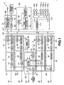
- This invention is applied to, e.g, A/V (Audio/Video) server 1 constituted as shown in FIG. 1 .
- This A/V server 1 records and/or reproduces (hereinafter referred to as records/reproduces) audio and/or video data (hereinafter referred to as A/V data) with respect to recording medium.
- This A/V server 1 can carry out editing processing in addition to recording/reproduction processing of A/V data by allowing user to operate the control panel.
- the A/V server 1 comprises a recording port 10, reproduction ports 20, 30, 40, an editing manager 50, a video effecter 60, a control panel 70, a timing manager 80, a file manager 90, and a HDD 110 array including HDDs (Hard Disc Drives) 100 1 , 100 2 , ⁇ , 100 n-3 , 100 n-2 ,100 n-1 , 100 n (n is arbitrary integer) respectively provided with plural recording media.
- HDDs Hard Disc Drives
- the A/V server 1 comprises a data bus 120 for carrying out data transfer between the respective ports of the recording port 10 and the resproduction ports 20, 30, 40 and the HDD array 110, and a control bus 121 for transferring control signals for controlling respective sections.
- the A/V server 1 includes one input processing section and three output processing sections as described above, and is operative to carry out input/output processing of four systems.
- the recording port 10 functions as input processing section which carries out processing for recording signals inputted from an input terminal 18 onto the HDD array 110, or the like.
- This recording port 10 is composed of a data input/output section 11 and a data management section 12.
- the data input/output section 11 comprises a selector 13 and an encoder 14, and the data management section 12 comprises a serial-to-parallel conversion processing section (hereinafter referred to as S/P) 15, a buffer 16 and a CPU 17.
- S/P serial-to-parallel conversion processing section
- the selector 13 serves to select data to be encoded.
- the selector 13 selects, e.g., either one signal of data including video/audio data inputted from the input terminal 18 such as data in conformity with SDI (Serial Digital Interface) standardized by the SMPTE (Society of Motion Picture and Television Engineeers)-259M or data in conformity with SDTI (Serial Digital Transfer Interface) standardized by the SMPTE-305M, etc. and data outputted from an editing section 51 that the editing manager 50 has to output selected signal to the encoder 14 of the succeeding stage.
- SDI Serial Digital Interface
- SMPTE Society of Motion Picture and Television Engineeers
- SDTI Serial Digital Transfer Interface
- the encoder 14 encodes the signal outputted from the selector 13 into a signal having a predetermined format.
- the encoder 14 carries out compression-encoding by the MPEG (Moving Picture Experts Group) system with respect to inputted signal.
- MPEG Motion Picture Experts Group
- the encoder 14 there may be carried out processing to take out or extract video signals and/or audio signals from data in conformity with the above-described SDTI, and there may be carried out combination of the above-described processing. It is to be noted that, in the following description, the encoder 14 is assumed to undergo compression encoding of inputted signal to output it. The compressed data generated by compression-encoding of the encoder 14 is inputted to the S/P 15 in the data management section 12.
- the S/P 15 in the data management section 12 carries out serial-to-parallel conversion so as to permit compressed data inputted from the encoder 14 to be written onto respective HDDs 100 1 , 100 2 , ⁇ , 100 n-3 , 100 n-2 , 100 n-1 , 100 n . Respective data obtained after undergone serial-to-parallel conversion by this S/P 15 are delivered to the buffer 16 of the succeeding stage as occasion demands.
- the buffer 16 is used for temporarily storing respective data outputted from the S/P 15 to, e.g., send out respective data after undergone time division multiplexing. Although not shown, the buffer 16 is caused to be of configuration to individually hold respective data outputted from the S/P 15. The buffer 16 is supplied with respective data from the S/P 15 as occasion demands. When time slot from a timing pulse generator 81 is assigned to the CPU 17, the buffer 16 outputs data subject to buffering to the data bus 120 within a predetermined time period permitted by the time slot under control of the CPU 17.
- the data bus 120 is called SBX (Spydar Bus eXtension) bus, and is separated, although not shown, into up-stream bus for carrying out transmission of data only in a direction to record data and down-stream bus for carrying out transmission of data in a direction to reproduce data, wherein these up-stream bus and down-stream bus are respectively constituted by plural buses for individually carrying out transmission of respective data which have been converted from serial data into parallel data at the S/P 15.
- SBX Synchrodar Bus eXtension
- HDDs 100 1 , 100 2 , ⁇ .,100 n-3 100 n-2 , 100 n-1 , 100 n are superimposed onto respective data outputted from the buffer 16 so as to become in conformity with transmission format of the data bus 120.
- the CPU 17 controls respective sections of the recording port 10 on the basis of, e.g., control signals such as external command, etc. transmitted from control panel 70 through the control bus 121. Moreover, the CPU 17 transfers, as occasion demands, given control signal to CPU 53 that the editing manager 50 has. Further, the CPU 17 controls output of data held in the buffer16 on the basis of time slot assigned by timing pulse generator 81.
- Such recording port 10 can input video data and audio data of 4 channels or 8 channels.
- the reproduction port 20 functions as output processing section which carries out processing for outputting, to the external, data recorded on the HDD array 110, and is composed of a data management section 21 and a data input/output section 22.
- the data management section 21 comprises a buffer 23, a parallel-to-serial conversion processing section (hereinafter referred to as P/S) 24 and a CPU 25, and the data input/output section 22 comprises a decoder 26 and a selector 27.
- P/S parallel-to-serial conversion processing section
- the buffer 23 temporarily stores respective data sent in parallel through the data bus 120 from the HDD array 110.
- the buffer 23 is constituted so as to individually hold respective data outputted in parallel from the HDD array 110 although not shown.
- the buffer 23 reads out, under control of the CPU 25, data from the HDD array 110 to input it. Namely, when data is read out from the HDD array 110 by the time slot, command to instruct reproduction by control of the CPU 17 is outputted from the buffer 16 to the HDD array 110 through the data bus 120 at a certain time slot period. Then, data is reproduced within the HDD array 110 at the subsequent time slot period. Thus, the reproduced data is outputted from the data bus 120 to buffers 23, 33, 34 in accordance with the above-described SBX format.
- the P/S 24 converts parallel data outputted from the buffer 23 into serial data.
- the data obtained after undergone parallel-to-serial conversion by this P/S 24 is delivered to the decoder 26 in the data input/output section 22.
- the CPU 25 controls respective sections of the reproduction port 20 on the basis of control signals such as external command, etc. transmitted through the control bus 121. In addition, the CPU 25 transfers given control signals to CPU 53 that the editing manager 50 has as occasion demands.
- the decoder 26 in the data input/output section 22 decodes serial data inputted from the P/S 24 by a predetermined decode processing.
- This decoder 26 expands data reproduced from the respective HDDs 100 when they are compression-encoded to convert such data into the above-described SDI data, etc. to output them.
- Various data including video/audio data obtained as the result of the fact that they are decoded by this decoder 26 are inputted to selector 27 or editing section 51 that the editing manager 50 has.
- the selector 27 serves to select signal which is outputted to the external through output terminal 28. In more practical sense, the selector 27 selects either one signal of data outputted from the decoder 26 and data outputted from the editing section 51 that the editing manager 50 has to deliver the selected signal to the output terminal 28 as SDI data or SDTI data.
- Such reproduction port 20 can output video data and audio data of 4 channels or 8 channels.
- Reproduction ports 30, 40 are both constituted similarly to the reproduction port 20.
- the reproduction port 30 is composed of a data management section 31, and a data input/output section 32.
- the data management section 31 comprises a buffer 33 for temporarily storing data from the HDD array 110, a P/S 34 for converting parallel data from the buffer 33 into serial data, and a CPU 35 for controlling respective sections of the reproduction port 30.
- the data input/output section 32 comprises a decoder 36 for decoding serial data inputted from the P/S 34, and a selector 37 for selecting either one signal of data outputted from this decoder 36 and data outputted from the editing section 51 to deliver the selected signal to output terminal 38.
- the reproduction port 40 is composed of a data management section 41 and a data input/output section 42.
- the data management section 41 comprises a buffer 43 for temporarily storing data from the HDD array 110, a P/S 44 for converting parallel data from this buffer 43 into serial data, and a CPU 45 for controlling respective sections of the reproduction port 40.
- the data input/output section 42 comprises a decoder 46 for decoding serial data inputted from the P/S 44, and a selector 47 for selecting either one signal of data outputted from this decoder 46 and data outputted from the editing section 51 to deliver the selected signal to output terminal 48.
- the editing manager 50 comprises editing section 51, an interface (I/F) 52 and a CPU 53 and serves to output data inputted from the recording port 10 and the reproduction ports 20, 30, 40 which are described above to a video effector 60 through the editing section 51 to allow it to carry out editing.
- the editing manager 50 outputs data from the video effecter 60 to the selector 13 of the recording port 10 and the selectors 27, 37, 47 of the reproduction ports 20, 30, 40.
- the editing section 51 suitably switches desired data of data inputted to the recording port 10 and data after passing through decoders 26, 36, 46 of the reproduction ports 20, 30, 40 by switcher (not shown) provided therewithin to select such desired data to output it to the video effecter 60. Moreover, the editing section 51 suitably switches data inputted from the video effecter 60 by switcher to thereby output it to desired port or CPU 53. Further, in the case where there is necessity to output, to external monitor unit, etc., data inputted to the recording port 10, data after passing through decoders 26, 36, 46 of the reproduction ports 20, 30, 40 and data inputted from the video effecter 60, the editing section 51 delivers such data to output terminal 54. It is to be noted that there are instances where switching is only carried out to output data to the reproduction ports 20, 30, 40 and the recording port 10, such as, for example, instances where material A is inserted into material B and is only outputted so that effect is not applied at the editing point.
- the I/F 52 is connected to the control panel 70, and is supplied with control signal for controlling the control panel 70 and/or A/V data, etc. from CPU 53 to output it to the control panel 70, and to input, to the CPU 53, operation input signal, etc. from the control panel 70.
- the I/F 52 is connected to, e.g., external VTR (Video Tape Recorder), etc. to output data and/or various commands, and to input various commands from the external.
- VTR Video Tape Recorder
- the CPU 53 executes editing processing execution program stored therein to thereby control the CPU 17 that the recording port 10 has and the CPUs 25, 35, 45 that the reproduction ports 20, 30, 40 respectively have.
- the CPU 53 controls CPUs of respective ports to thereby control plural ports at the same time, and to output, to the HDD array 110, control signal indicating read-out of A/V data stored in the respective HDDs 100 to input A/V data.
- the CPU 53 reads out material data subject to editing processing in accordance with Virtual File List (hereinafter referred to as VFL) to output it to the control panel 70 through the I/F 52.
- VFL Virtual File List
- this CPU 53 carries out preview processing based on VFL generated as the result of editing processing in accordance with operation input signal indicating execution of preview processing from the control panel 70. At this time, the CPU 53 reads out VFL stored in a file management section 91 to read out A/V data that VFL indicates through respective ports 20 to 40 from respective HDDs 100 in sequence to output such data to the control panel 70 through the I/F 52.
- this CPU 53 carries out VTR emulation processing when reproducing A/V data after undergone editing. Namely, when VTR emulation processing is carried out so that operation input signal indicating execuition of display on a display section 301 of the control panel 70 is inputted, this CPU 53 sequentially reads out, on the basis of VFL, data from the preroll point positioned forward on the time axis with respect to in points set in respective material data subject to editing processing until postroll point positioned backward on the time axis with respect to the out points to output such data to the control panel 70 through the I/F 52. It is to be noted that time with respect to in point of the preroll point can be arbitrarily set, and time with respect to out point of the postroll point can be arbitrarily set.
- this CPU53 carries out processing to sequentially read out data from the preroll point until the postroll point in accordance with editing point set in respective material data thereafter to output data to the control panel 70 so as to display still picture positioned at the in point or out point set in respective data which have been read out, or processing to output, to the control panel 70, control signal to carry out Cue Up processing for displaying still picture positioned at in point or out point stored in a flash memory 304 of the control panel 70.
- the video effecter 60 implements special effect processing to data by making use of plural ports 20 to 40.
- the video effecter 60 carries out, with respect to material data inputted from the editing manager 50, processing for carrying out special effect processing such as Picture-in-Picture (PinP), etc. to insert other different material data into certain material data to connect respective material data to thereby generate new time series data.
- PinP Picture-in-Picture
- the control panel 70 comprises, e.g., various switches, etc. that user operates when carrying out selection of data for carrying out editing work or selecting port for carrying out input/output of data, and display section, etc. for displaying picture, etc. used in editing work.
- the control panel 70 generates, as the result of the fact that it is operated by user, an operation input signal corresponding to that operation.
- control panel 70 is adapted so that when user operates various switches, etc. to thereby select recording port 10, reproduction ports 20, 30, 40 and VTR connected to the external, etc., it outputs control signal to the selected port or VTR.
- This control signal is sent to control bus 121 through timing manager 80, and is caused to undergo transmission by the control bus 121.
- the control signal thus transmitted is inputted to CPUs that respective ports have.
- Respective ports or VTR to which control signal is sent carry out operation corresponding to the content of this control signal.
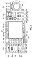
- the control panel 70 comprises plural buttons, etc. operated by user, and is roughly classified into a port select section 201, a traveling control section 202, a search operation section 203, a time code section 204, a function operation and display section 205 and an editing operation section 206.
- This port select section 201 is the section in which there are provided a group of buttons for allowing user to select recording port 10 and reproduction ports 20, 30, 40, and comprises a port select button (PORT SELECT) 211 for selecting respective ports 10, 20, 30, 40, a recorder button (RECORDER) 212 for selecting ports 10, 20, 30, 40 caused to function as data input port at the time of editing processing, and a player button (PLAYER) 213 for selecting ports 10, 20, 30, 40 caused to function as data output port at the time of editing processing.
- PORT SELECT port select button
- RECORDER recorder button
- PLAYER player button
- the travelling control section 202 is the section in which there are provided a group of buttons for allowing user to control recording/reproduction processing, and comprises a preroll button (PREROLL) 221 for implementing VTR emulation processing to carry out reproduction, a recording button (REC) 222 for a tarting recording, an editing button (EDIT) 223 for carrying out editing processing, a stop button (STOP) 224 for stopping recording and reproduction, a fast feed button (F FWD) 225 for executing fast feed in the forward direction of the time axis, a play button (PLAY) 226 for starting reproduction, and a rewinding button (REW) 227 for executing rewinding in reverse direction of the time axis.
- PREROLL preroll button
- REC recording button
- EDIT editing button
- STOP stop button
- F FWD fast feed button
- PLAY play button
- REW rewinding button
- the search operation section 203 is the operation section that user controls retrieval processing of material data, and comprises a search dial 231 for retrieving editing points (in point, out point) at the time of editing processing, a variable button (VAR) 232 for carrying out variable mode reproduction to control reproduction speed (velocity) in dependency upon position of the search dial 231, a jog button (JOG) 233 for carrying out jog mode reproduction to control reproduction speed (velocity) in dependency upon rotational speed (velocity) of the search dial 231, and a shuttle button (SHUTTLE) 234 for carrying out shuttle mode reproduction to control reproduction speed (velocity) in a range broader that of the jog mode reproduction in dependency upon rotational speed (velocity) of the search dial 231.
- VAR variable button
- JOG jog button
- SHUTTLE shuttle button
- the time code section 204 comprises, as buttons that user controls in regard to time code, a time code display switching button (TC TYPE) 241 for switching time code display, a time code/user bit button (TC/UB) 242 for displaying user bit or bits inserted into time codes of selected ports 10, 20, 30, 40, a reset button (RESET) 243 for resetting time code in dependency upon kind of time code, a hold button (HOLD) 244 for controlling display of time code dialog, a reproduction (playback) signal monitor button (PB) 245 for selecting reproduction signal as A/V data outputted from respective ports 10, 20, 30, 40, and an input signal monitor button (PB.FE) 246 for selecting input of predetermined mode as video/audio signal outputted from respective ports 10, 20, 30, 40.
- TC TYPE time code display switching button
- TC/UB time code/user bit button
- REET reset button
- HOLD hold button
- PB reproduction (playback) signal monitor button
- PB reproduction signal monitor button
- PB.FE input signal monitor button
- the function operation and display section 205 comprises function buttons (L1 to L11) 251 for executing respective functions in correspondence with functions displayed on display, a display section 252, function buttons (B1 to B7) 253, a shift button (SHIFT) 254 for switching function assignment every function buttons 251, 253, a mode button (MODE) 255 for designating operation mode, and a multi-control (MULTI CONTROL) knob 256 for carrying out cursor movement, etc. displayed on the display section 252.
- function buttons (L1 to L11) 251 for executing respective functions in correspondence with functions displayed on display
- function buttons (B1 to B7) 253 for switching function assignment every function buttons 251, 253, a mode button (MODE) 255 for designating operation mode
- MODE mode button
- MULTI CONTROL multi-control
- the editing operation section 206 comprises a delete button (DELETE) 261 for carrying out deletion of already set editing point and release of DMC mode, an editing in/out point designation button (IN/OUT) 262 for setting in point and out point, an editing point setting button (ENTRY) 263 for setting in point and out point along with the editing in/out point designation button 262, an audio in point/out point designation button (AUDIO IN/OUT) 264 for setting in point and out point with respect to audio data, a trimmer button (TRIM) 265 for trimming already set in point and out point, a memory lamp (MEMORY) 266 which is turned ON when reproduction processing setting at an arbitrary reproduction speed (velocity) is stored, a review button (REVIEW) 267 for displaying reproduction of A/V data after undergone editing processing, an automatic editing button (AUTO EDIT) 268 for carrying out automatic editing, a preview button (PREVIEW) 269 for carrying out preview reproduction of editing processed A/V data before recording, and a DMC editing button (DMC EDIT)
- control panel 70 As shown in FIG. 3 , display section 301, display memory 302, CPU 303, flash memory 304, operation input section 305 and capture controller 306 are connected to bus 307, and the respective sections are adapted so that input/output of data can be made through the bus 307.
- the display section 301 corresponds to the above-described display section 252, and is comprised of, e.g., LCD (Liquid Crystal Display) and serves to read thereinto A/V data stored in the display memory 302 to display image that A/V data such as moving picture or still picture, etc. indicates.
- LCD Liquid Crystal Display
- the operation input section 305 includes the above-described various buttons or search dial 231, etc. that user operates, and is adapted so that button, etc. is caused to undergo pressing operation by user, it generates operation input signal corresponding to each button to output it to the CPU 303 and the capture controller 306.
- the capture controller 306 is supplied with A/V data from information management section 3 through data bus 120 and network driver 92, and carries out processing to capture inputted A/V data to generate still picture data to output the still picture data thus generated to the flash memory 304.
- the CPU 303 is adapted to store processing program in the memory included therewithin, and carries out processing in accordance with the processing program.
- This CPU 303 displays file names, etc. stored in respective HDDs 100.
- this CPU 303 sets out point in the first material data and sets in point and out point in the second and third material data in accordance with an operation input signal corresponding to the fact that user operates editing operation section 206 when generating edit data in which the first to third material data are connected as shown in FIG. 4 by using, e.g., first to third material data subject to editing processing to thereby prepare VFL in which the in point and the out point set in the respective material data are described by time codes as shown in FIG. 5 .
- the CPU 303 prepares VFL consisting of name of VFL, in points and out points of the first to third material data indicating image, and in points and out points of the first to third material data indicating sound.
- VFL consisting of name of VFL, in points and out points of the first to third material data indicating image, and in points and out points of the first to third material data indicating sound.
- A/V data from 0 to 5 seconds of the first material data is reproduced
- A/V data from 10 to 15 seconds of the second material data is subsequently reproduced
- A/V data from 5 to 10 seconds of the third material data is reproduced.
- Timing manager 80 serves to take timing on the basis of synchronizing signal of video to carry out management of data bus 120.
- This timing manager 80 comprises a timing pulse generator 81 for generating timing pulse, interface (I/F) 82 which is interface with the control panel 70, and CPU 83 for controlling respective sections.
- This timing manager 80 allows CPU 83 to control timing pulse generator 81 to generate timing pulse on the basis of video synchronizing signal inputted from the external to transmit it to control bus 121.
- the timing manager 80 carries out management of use right of the data bus 120 on the basis of this timing pulse.
- a file manager 90 comprises a file management section 91 for holding file management information indicating recording areas of files on respective HDDs 100 to carry out management of file on the basis of this file management information, a network driver 92 connected to external network, e.g., ethernet, etc. to carry out input/output of data between the network driver and external network, and a CPU 93 for controlling respective sections.
- a file management section 91 for holding file management information indicating recording areas of files on respective HDDs 100 to carry out management of file on the basis of this file management information
- a network driver 92 connected to external network, e.g., ethernet, etc. to carry out input/output of data between the network driver and external network
- a CPU 93 for controlling respective sections.
- the file manager 90 carries out management of data recorded on the HDD array 110 under control of the CPU 93. For example, when a certain file is recorded onto HDD, the file manager 90 carries out management of data recorded on the HDD array 110 by using file management information including information indicating address in which file is recorded within each HDD 100.
- the file management section 91 can hold file management information to thereby only designate file name to carry out reproduction of desired file, and can reproduce material data in accordance with editing result without newly recording data in editing on the basis of VFL which is reproduction file information.
- the file management information consists of three information of File Entry (hereinafter referred to as FE), Record Entry (hereinafter referred to as RE) and Free Space List (hereinafter referred to as FSL).
- FE File Entry
- RE Record Entry
- FSL Free Space List
- A/V server 1 is adapted so that FEs are set in file units, and are linked to RE indicating information which indicates position on HDD 100 on which that file is written and written length thereof.
- file A is recorded in a manner divided into address 50 to address 100, address 200 to address 300, and address 500 to address 750 in address space on the HDD 100.
- FSL includes pointer infomation to the next FSL, leading position data indicating address of leading position of continuous space area on the HDD 100 where no data is recorded, and a continuous area length indicating length of space area from address of this leading position until the area where data is next recorded.
- FSLs are prepared by the same number as the number of continuous space areas.
- "0" which is the first address of the space area on the HDD is described as leading position data
- "50” is described as continuous area length because file A is recorded from address 50.
- "100” is described as leading position data
- "100” is described as continuous area length because file A is recorded from address 200.
- "300" is described as leading position data
- "200” is described as continuous area length because file A is recorded from address 500.
- EOF End Of File
- the file management section 91 holds such file management information and is adapted so that when other file is recorded onto HDD 1 , HDD 2 , ⁇ ., 100 n-3 , 100 n-2 , 100 n-1 , 100 n , it prepares FE and RE relating to that file to rewrite FSL.
- the A/V server 1 which holds such file management information is operative so that when editing, as material data, A/V data recorded on HDD 100 1 , 100 2 , ⁇ , 100 n-3 , 100 n-2 , 100 n-1 , 100 n to output information indicating that file from the control panel 70 to the HDD array 110.
- the CPU 53 of the editing manager 50 can grasp area to be accessed of HDD 100 1 , 100 2 , ⁇ , 100 n-3 , 100 n-2 , 100 n-1 , 100 n for the purpose of reproducing desired file on the basis of file management information.
- User determines information of editing point, etc., such as, for example, in point and out point by operating various switches, etc.
- the A/V server 1 outputs editing result information determined in this way from the control panel 70 to the HDD array 110 for a second time. At this time, in the A/V server 1, it is sufficient to output only editing result information from the control panel 70 to the HDD array 110 and it is unnecessary to send material data itself.
- the HDD array 110 stores various data with respect to respective HDDs and carries out management thereof.
- the HDD array 110 is adapted so that there are connected plural HDDs, 100 1 , 100 2 , ⁇ , 100 n-3 , 100 n-2 , 100 n-1 , 100 n , and stores various data with respect to these HDDs 100 1 ,100 2 , ⁇ , 100 n-3 , 100 n-2 , 100 n-1 , 100 n and carries out management of data stored in these HDDs 100 1 , 100 2 , ⁇ ., 100 n-3 , 100 n-2 , 100 n-1 , 100 n .
- the HDD array 110 comprises a buffer 111, a video data write/read processing section (V) 112, and an audio data write/read processing section (A) 113.
- the buffer 111 temporarily stores data when carrying out transfer of data n between the buffer 111 and the data bus 120. For example, data from the respective HDDs 100 are caused to undergo buffering at this buffer 111, and is then outputted to the data bus 120.
- the video data write/read processing section 112 carries out write and read processing of video data with respect to the respective HDDs 100 connected thereto. In more practical sense, the video data write/read processing section 112 selects desired HDD 100 from the respective HDDs to write video data inputted from the buffer 111 and to read out video data from the desired HDD to output it to the buffer 111.
- the audio data write/read processing section 113 carries out write and read processing of audio data with respect to the respective HDDs 100 n-1 , 100 n connected thereto. In more practical sense, the audio data write/read processing section 113 selects either one of two HDDs 100 n-1 , 100 n connected thereto to write audio data inputted from the buffer 111, and to read audio data from the desired HDD 100 to output it to the buffer 111.
- the HDD array 110 is caused to have redundancy such that, e.g., data to be recorded as broadcast business is sec n urely recorded and data recorded is securely reproduced, and takes RAID (Redundant Arrays of Inexpensive Disks) configuration.
- HDDs 100 1 ,100 2 , ⁇ ,100 n-3 , 100 n-2 onto which video data is recorded is caused to be of configuration of RAID-3, i.e., configuration in which data are transferred in parallel in a manner divided into plural discs and parity disc is further provided.
- HDD 100 n-1 , 100 n onto which audio data is recorded takes configuration of RAID-1 so called mirror disc to carry out double write operation of data.
- data inputted to the input terminal 18 is inputted to the encoder 14 via the selector 13 that the data input/output section 11 of the recording port 10 has so that such data is encoded into data of a predetermined format.
- the encoded data is converted into parallel data by the S/P 15 that the data management section 12 of the recording port 10 has, and is caused to undergo buffering at the buffer 16. Further, the data which has been caused to undergo buffering is outputted to the data bus 120 for a time period of time slot assigned to the CPU 17 from the timing pulse generator 81, and is transferred to the HDD array 110.
- the data transferred to the HDD array 110 is caused to undergo buffering at the buffer 111, and is read out therefrom. Further, among the data which have been read out from the buffer 111, video data is inputted to the video data write/read processing section 112 and audio data is inputted to the audio data write/read processing section 113.
- the video data write/read processing section 112 divides the inputted video data in predetermined units, and determines parity data to record the divided data and the parity data onto respective HDDs 100 1 , 100 2 , ⁇ , 100 n-3 , 100 n-2 .
- the audio data write/read processing section 113 records the inputted audio data onto two HDDs 100 n-1 , 100 n .
- the file management section 91 generates new file management information consisting of file names and addresses of recording areas of respective HDDs 100 where data are recorded in accordance with the recorded data.
- the A/V server 1 carries out such a processing, thereby making it possible to record data inputted from the external onto the HDD array 110.
- one of the reproduction ports 20, 30, 40 provides access to the HDD array 110 at time period of time slot assigned by the timing pulse generator 81 to make a request for reproduction of data with respect to the HDD array 110.
- the video data write/read processing section 112 reads out video data and parity data recorded, in a divided manner, on HDDs 100 1 , 100 2 , ⁇ , 100 n-3 , 100 n-2 to unify (integrate) the divided data, and to carry out error detection and error correction on the basis of parity data to reproduce video data.
- the audio data write/read processing section 113 reproduces audio data from the HDD where there is no error of two HDDs 100 n-1 , 100 n .
- the video data write/read processing section 112 and the audio data write/read processing section 113 access file to be reproduced by making reference to file management information stored on respective HDDs 100 or the file management section 91.
- the reproduced video/audio data is read out after undergone buffering at the buffer 111 and is read out therefrom.
- the data thus read out is transferred to reproduction port which has carried out reproduction request through the data bus 120.
- the A/V server 1 when, e.g., reproduction port 20 makes a reproduction request, data outputted from the HDD array 110 is inputted to the buffer 23 that the data management section 21 has through the data bus 120.
- the data inputted to the buffer 23 is converted into serial data at the P/S 24 after undergone buffering at this buffer 23.
- serial data is inputted to the decoder 26 that the data input/output section 22 has, at which it is decoded.
- the data thus decoded is delivered to the output terminal 28 via the selector 27, and is outputted to the external.
- the A/V server 1 can reproduce internal material to output it to the external.
- the A/V server 1 holds file management information that the above-described file management section 91 carries out management, thereby making it possible to carry out operation such as reproduction, etc. of file only by designating file name.
- the A/V server 1 can reproduce internal material in accordance with editing result without newly recording data in editing on the basis of VFL.
- the editing result information is called the above-described VFL.
- the A/V server 1 provides access to predetermined addresses of respective HDDs on the basis of the above-mentioned VFL to sequentially read out recorded material data, thereby making it possible to output edit data based on VFL to the control panel 70 to present it to user. Namely, there is no necessity that when carrying out editing processing, edit data serving as editing result are re-recorded onto respective HDDs 100. For this reason, the A/V server 1 can edit material data on the real time basis to output such data.
- the VFL consists of a file name area indicating edited file name, and a reproduction start position area and a reproduction end position area respectively indicating in point and out point set with respect to material data included in that file.
- the reproduction start position area and the reproduction end position area respectively indicate reproduction start position and reproduction end position corresponding to addresses on the HDD from the leading position of that file.
- VFL which designates reproduction start position [10] and reproduction end position [60] is prepared as shown in FIG. 11(A) with respect to file A recorded, in a manner divided into three areas of address 50 to address 100, address 200 to address 300 and address 500 to address 750 in address space on the above-described HDD shown in FIG. 7 , correspondence of actual reproduction start position and reproduction end position on the HDD is as shown in FIG. 11(B) .
- the VFL shown in FIG. 11(A) designates editing period of length [50] indicated by reproduction start position [10] and reproduction end position [60] with respect to the file A.
- the file A is recorded from address 50 in address space on the HDD. Accordingly, start position of editing period, i.e., in point of file A given by the reproduction start position [10] indicated at VFL is address 60 in which "10" is added to the address 50.
- reproduction end position [60] indicated at the VFL indicates end position of editing period, i.e., out point of continuous length [50] from reproduction start position [10] (address 60) on the address space, and is address 210 which corresponds to end position of editing period of address 60 to address 100 and address 200 to address 210.
- the VFL shown in FIG. 11(A) designates address 60 to address 100 and address 200 to address 210 as editing period of continuous file A.
- step ST1 When editing processing is carried out by the A/V server 1, initially, at step ST1, user operates the port select button 211 of the port select section 201 so that operation input signal is inputted to the CPU 53 of the editing manager 50 through the timing manager 80 and the control bus 121. Responding thereto, the CPU 53 selects A/V data inputted from the recording port 10 as second material data (A/V data of the Recorder side).
- step ST1 user further operates the port select button 211 of the port select portion 201 so that operation input signal is inputted to the CPU 53.
- the CPU 53 reads out A/V data stored on the HDD 100 by making reference to file management information held at the file management section 91 to select this A/V data as first material data (A/V data of the Player side).
- the CPU 303 of the control panel 70 carries out processing to display, on the display section 301, data retrieval picture as shown in FIG. 13 in accordance with control signal indicating execution of editing processing from the CPU 53.
- the CPU 303 displays No. of file 401 stored in each HDD 100 as file, file name 402, latest updating date 403, select/non-select pointer 404, picture 405 that material data stored in selected file indicates, No. of selected file 406, time length 407 of selected file, latest updating date 408 of selected file, and port No. 409 of designated each port.
- the CPU 303 serves to move the select/non-select pointer 404 by operation input signal corresponding to the fact that user operates search dial 231 to select first material data.
- the CPU 53 serves to shift to processing for setting editing point of step ST2 to output an operation input signal to the effect that corresponding picture is caused to be editing processing picture to the CPU 303 of the control panel 70.
- the CPU 303 allows the display section 301 to display editing processing picture as shown in FIG. 14 .
- the CPU 303 displays port No.
- picture display area 413 including moving picture 412 of first material data or second material data, and still pictures 412b, 412c of first material data and second material data in which in point and out point are set, time code 414 of in point set at material data that set port holds, time code 415 of out point, time code 416 indicating time between in point and out point, time code 417 of first material data, and time code 418 of second material data.
- step ST2 editing processing picture as shown in FIG. 14 is displayed, and user operates the control panel 70 so that editing periods are designated every respective material data.
- preroll period and postroll period are stored in advance into flash memory 304 by operation of the control panel 70.
- the CPU 303 of the control panel 70 generates time code of in point and time code of out point indicating editing periods designated with respect to the first and second material data, and calculates respective positions of preroll point and postroll point from the time codes of in point and out point to output, to the file management section 91, the time code of in point and the time code of out point with respect to respective material data.
- the CPU 303 subtracts time corresponding to preroll period, which has been read out from the memory 304, from time code of designated in point to thereby calculate preroll point, and adds time corresponding to postroll period to time code of out point to thereby calculate postroll point.
- Information of the calculated preroll and postroll points are transferred to the CPU 53 of the editing manager 50 via I/F 82 and CPU 83 of the timing manager 80 and the control bus 121.
- the CPU 303 of the control panel 70 allows automatic editing button 268 to undergo flashing to carry out display to the effect that in point and out point are set at first and second material data so that editing processing can be made.
- step ST3 the CPU 53 judges operation input signal indicating that preview button 269 or automatic editing button 268 of the control panel 70 has been operated. Further, when the preview button 269 is pushed down, the processing procedure proceeds to step ST4 to carry out preview reproduction processing. When the automatic editing button 268 is pushed down, the processing procedure proceeds to step ST8 to carry out automatic editing processing.
- the CPU 53 prepares VFL for preview to sequentially reproduce data from the preroll point to the postroll point in accordance with editing points set at respective material data on the basis of this VFL for preview.
- the CPU 53 carries out processing to convert time codes indicating in points and out points every respective material data set at the above-described step ST2 into addresses within the HDD to thereby control the file management section 91 so as to prepare VFL for preview having data structure as shown in FIG. 10 every respective material data.
- the CPU 53 reproduces areas including editing points (in point and out point) of respective material data by using VFL for preview prepared at the above-described step ST4 to output them to the control panel 70 to allow the display section 301 to display image based on VFLfor preview to thereby carry out preview reproduction.
- the CPU 53 carries out VTR emulation processing shown in FIG. 15 in accordance with the operation input instruction corresponding to the fact that preroll button 221 is pushed down. Namely, the CPU 53 is operative so that when operation input signal to the effect that display is conducted on the display section 301 of the control panel 70 is inputted, it sequentially reads out, from respective reproduction ports 20, 30, 40, data from the preroll points to the postroll points of respective materials by using information of the preroll point and the postroll point and VFL for preview prepared at the step ST2 to output them to the control panel 70 through the I/F 52.
- reproduction is initially conducted from the preroll point of the first material data up to the in point thereof, reproduction is subsequently carried out from the in point to the out point of the second material data, and reproduction is subsequently carried out from the out point to the postroll point of the first material data.
- step ST6 the CPU 53 conducts a control so as to delete, from the file management section 91, VFL for preview used when preview reproduction is carried out at the above-described step ST5.
- the CPU 53 carries out Cue Up processing to thereby control the control panel 70 so as to display still picture positioned at the in point or the out point set at material data reproduced at the above-described step ST5.
- the CPU 303 outputs, to the display memory 302, still picture positioned at the in point or the out point stored in the flash memory 304 to complete processing.
- reproduction is carried out up to the postroll point of the first material data at step ST5
- reproduction is carried out up to the out point of the first material data toward opposite direction of the time axis from the postroll point of the first material data at step ST7.
- the CPU 53 controls the file management section 91 so as to prepare VFL on the basis of in points and out points set every respective material data at the step ST2.
- the CPU 53 carries out VTR emulation processing to read out, from respective ports, respective material data from the preroll point to the postroll point similarly to the above-described step ST5 in accordance with the VFL prepared at the above-described step ST8 to display them on the display section 301 of the control panel 70, thus to carry out reproduction.
- the CPU 53 carries out Cue Up processing similarly to the above-described step ST7 to thereby control the control panel 70 so as to display still picture positioned at the in point or the out point set in the reproduced material data.
- the CPU 303 outputs, to the display memory 302, still picture positioned at the in point or the out point stored in the flash memory 304 to complete processing.
- the VFL file prepared at the above-described step ST8 is stored into memory or the HDD 100 included within the file management section 91 as editing result.
- the CPU 303 allows picture positioned at the time point when the above-mentioned operation input signal is inputted to be picture at the out point. Namely, the CPU 303 allows picture stored in the display memory at the time point when the operation input signal is inputted to be picture at out point. Further, the CPU 303 outputs, to the file management section 91, time codes indicating the in point and the out point set with respect to material data through the timing manager 80 and the control bus 121 to thereby allow it to prepare VFL.
- the CPU 303 is adapted so that in the case where the in point and the output point are set in advance in material data displayed on the display section 301, when operation input signal to the effect that user pushes down stop button 224 is inputted from the operation input section 305, the CPU 303 changes picture at the out point set in advance to picture positioned at the time point when the above-mentioned operation input signal is inputted. Further, the CPU 303 outputs, to the file management section 91, time codes indicating out point and in point set for a second time with respect to material data through the timing manager 80 and the control bus 121 to allow it to prepare VFL. In accordance with the A/V server 1 which carries out such editing processing, even in the case where the in point and the out point are set in advance, it is possible to set the out point for a second time to prepare new VFL.
- VFL in which in points and out points are set in respective material data by time codes to prepare VFL described by address information at the file management section 91 to carry out preview reproduction and reproduction after editing processing of data from the preroll point to the postroll point set in the vicinity of the in point and the out point when reproducing material data on the basis of VFL. Accordingly, even when data recorded with respect to non-linearly reproducible recording medium is used to carry out editing processing, it is possible to present data after editing in a sense similar to VTR when carrying out emulation of VTR operation to present it to user.
- the data recording/reproducing apparatus and the data recording/reproducing method there is employed such an approach to set in point and out point in first and second material data to generate editing processing information for inserting the second material data into the first material data to prepare, on the basis of the editing processing information, first virtual file in which recording area of non-linearly accessible recording medium with respect to the first material data is described by time code and second virtual file in which recording area of recording medium with respect to the second material data is described by time code, thus making it possible to carry out, on the basis of time codes included in the first and second virtual files, reproduction from preroll point positioned forward in point of time with respect to the in point up to the postroll point positioned backward in point of time with respect to the out point.
Landscapes
- Engineering & Computer Science (AREA)
- Multimedia (AREA)
- Signal Processing (AREA)
- Television Signal Processing For Recording (AREA)
- Management Or Editing Of Information On Record Carriers (AREA)
Claims (10)
- Datenaufzeichnungs-/-wiedergabevorrichtung mit:einem nichtlinearen Aufzeichnungsmedium (110),einer Aufzeichnungs-/Wiedergabeeinrichtung (112) zum Aufzeichnen/Wiedergeben eines ersten Materials, das Video- und/oder Audio-Daten aufweist, auf/von dem Aufzeichnungsmedium (110), undeiner Mehrzahl von Eingabe-/Ausgabeverarbeitungseinrichtungen (10, 20, 30, 40) zum Verarbeiten des ersten Materials oder eines zweiten Materials, das von einem Äußeren eingegeben wird, und Ausgeben des ersten und/oder des zweiten Materials zu der Aufzeichnungs-/Wiedergabeeinrichtung zum Aufzeichnen, und zum Verarbeiten eines wiedergegebenen ersten und/oder zweiten Materials, das von der Aufzeichnungs-/Wiedergabeeinrichtung empfangen wird, und Ausgeben des ersten und/oder des zweiten wiedergegebenen Materials zu dem Äußeren, wobei jeweilige Eingabe-/Ausgabeverarbeitungseinrichtungen das erste und/oder das zweite Material innerhalb jeweiliger zugewiesener Zeitschlitzdauern in die Aufzeichnungs-/Wiedergabeeinrichtung eingeben oder von derselben ausgeben und die Datenaufzeichnungs-/-wiedergabevorrichtung folgende Merkmale aufweist:eine Bearbeitungseinrichtung (50) zum Bearbeiten des ersten Materials unter der Steuerung eines Benutzers, um Bearbeitungsinfonnationen zu erzeugen, die innerhalb des ersten Materials eine Bearbeitungsdauer mit einem Ein-Punkt und einem Aus-Punkt spezifizieren, in der das zweite Material aufzuzeichnen ist;eine Speichereinrichtung (304) zum Speichern einer Vorrolldauer und einer Nachrolldauer im Voraus;eine Informationsdatei-Vorbereitungseinrichtung (90) zum Vorbereiten einer lxzformationsdatei, die die Bearbeitungsdauer anzeigt und den Ein-Punkt und den Aus-Punkt der Bearbeitungsdauer innerhalb des ersten Materials aufweist, auf der Basis der Bearbeitungsinformationen; undeine Steuerungseinrichtung (50) zum Bestimmen eines Vorrollpunkts, der früher als der Ein-Punkt ist, durch Subtrahieren der Vorrolldauer von dem Ein-Punkt, und eines Nachrollpunkts, der später als der Aus-Punkt ist, durch Addieren der Nachrolldauer zu dem Aus-Punkt, anhand des Ein-Punkts und des Aus-Punkts, die in der Informationsdatei geliefert werden, und Steuern der Aufzeichnungs-/Wiedergabeeinrichtung, um auf der Basis der durch die Informationsdatei-Vorbereitungseinrichtung (90) vorbereiteten Informationsdatei das erste Material von dem Vorrollpunkt zu dem Ein-Punkt wiederzugeben, anschließend das zweite Material von dem Ein-Punkt zu dem Aus-Punkt wiederzugeben und anschließend das erste Material von dem Aus-Punkt zu dem Nachrollpunkt wiederzugeben, wobei die Steuerungseinrichtung die Informationsdatei löscht, wenn die Wiedergabe von dem Vorrollpunkt zu dem Nachrollpunkt bei der Aufzeichnungs-/Wiedergabeeinrichtung beendet ist.
- Datenaufzeichnungs-/-wiedergabevorrichtung nach Anspruch 1, bei der die Informationsdatei aus Informationen, die eine Wiedergabestartposition ab einer Aufzeichnungsstartposition, die auf dem Aufzeichnungsmedium des ersten Materials aufgezeichnet ist, anzeigen, und Informationen, die eine Wiedergabeendposition, die einer ab der Wiedergabestartposition wiederzugebenden Materiallänge entspricht, anzeigen, besteht.
- Datenaufzeichnungs-/-wiedergabevorrichtung nach Anspruch 1, ferner mit einer Anzeigeeinrichtung (252), auf der das erste und/oder das zweite Material, das von der Aufzeichnung-/ Wiedergabeeinrichtung wiedergegeben wird, angezeigt wird, wobei das erste Material, das von dem Vorrollpunkt zu dem Ein-Punkt und von dem Aus-Punkt zu dem Nachrollpunkt wiedergegeben wird, und das zweite Material, das von dem Ein-Punkt zu dem Aus-Punkt wiedergegeben wird, auf der Anzeigeeinrichtung angezeigt werden.
- DatenauE5eichnungs-/-wiedergabevonichtung nach Anspruch 1, bei der Informationen, die sich auf den Vorrollpunkt und den Nachrollpunkt beziehen, Zeitcodes sind.
- Datenaufzeichnungs-/-wiedergabevorrichtung nach Anspruch 1, bei der Informationen, die sich auf den Vorrollpunkt und den Nachrollpunkt beziehen, Adresswerte auf dem Aufzeichnurigsmedium sind.
- Datenaufzeichnungs-/-wiedergabeverfahren zum Aufzeichnen eines ersten Materials, das Video- und/oder Audio-Daten aufweist, auf einem nichtlinearen Aufzeichnungsmedium innerhalb einer zugewiesenen Schlitzdauer und zum Wiedergeben des auf dem Aufzeichnungsmedium aufgezeichneten ersten Materials innerhalb einer zugewiesenen Zeitschlitzdauer, wobei das batenaufzeichnungs-/- wiedergabeverfahren folgende Schritte aufweist:Aufzeichnen des ersten Materials;l3earbeiten des ersten Materials unter der Steuerung eines Benutzers, um Bearbeitungsinformationen zu erzeugen, die innerhalb des ersten Materials eine Bearbeitungsdauer mit einem Ein-Punkt und einem Aus-Punkt spezifizieren, in der ein zweites Material aufzuzeichnen ist;Speichern einer Vorrolldauer und einer Nachrolldauer im Voraus;Vorbereiten einer Informationsdatei, die die Bearbeitungsdauer spezifiziert, auf der Basis der BearbeitLingsinformationen, wobei die Informationsdatei den Ein-Punkt und den Aus-Punkt der Bearbeitungsdauer innerhalb des ersten Materials aufweist;Bestimmen eines Vorrollpunkts, der früher als der Ein-Punkt ist, durch Subtrahieren der Vorrolldauer von dem Ein-Punkt, und eines Nachrollpunkts, der später als der Aus-Punkt ist, durch Addieren der Nachrolldauer zu dem Aus-Punkt, anhand des Ein-Punkts und des Aus-Punkts, die in der Informationsdatei geliefert werden;Wiedergeben des ersten Materials von dem Vorrollpunkt zu dem Ein-Punkt auf der Basis der Informationsdatei,anschließend Wiedergeben des zweiten Materials von dem Ein-Punkt zu dem Aus-Punkt,anschließend Wiedergeben des ersten Materials von dem Aus-Punkt zu dem Nachrollpunkt, und,wenn das Wiedergeben von dem Vorrollpunkt zu dem Nachrollpunkt beendet ist, Löschen der Informationsdatei.
- Datenaufzeichnungs-/-wiedergabeverfahren nach Anspruch 6, bei dem die Informationsdatei aus Informationen, die eine Wiedergabestartposition ab einer Aufzeichnungsstartposition, die auf dem Aufzeichnungsmedium des ersten Materials aufgezeichnet ist, anzeigen, und Informationen, die eine Wiedergabeendposition, die einer ab der Wiedergabestartposition wiederzugebenden Materiallänge entspricht, anzeigen, besteht.
- Datenaufzeichnungs-/-wiedergabeverfahren nach Anspruch 6, das ferner ein Anzeigen des ersten Materials, das von dem Vorrollpunkt zu dem Ein-Punkt und von dem Aus-Punkt zu dem Nachrollpunkt wiedergegeben wurde, und des zweiten Materials, das von dem Ein-Punkt zu dem Aus-Punkt wiedergegeben wurde, auf einer Anzeigeeinrichtung aufweist.
- Datenaufzeichnungs-/-wiedergabeverfahren nach Anspruch 6, bei dem Informationen, die sich auf den Vorrollpunkt und den Nachrollpunkt beziehen, Zeitcodes sind.
- Datenaufzeichnungs-/-wiedergabeverfahren nach Anspruch 6, bei dem Informationen, die sich auf den Vorrollpunkt und den Nachrollpunkt beziehen, Adresswerte auf dem Aufzeichnungsmedium sind.
Applications Claiming Priority (3)
| Application Number | Priority Date | Filing Date | Title |
|---|---|---|---|
| JP25635199 | 1999-09-09 | ||
| JP25635199 | 1999-09-09 | ||
| PCT/JP2000/006167 WO2001018811A1 (fr) | 1999-09-09 | 2000-09-08 | Dispositif et procede d'enregistrement/lecture de donnees |
Publications (3)
| Publication Number | Publication Date |
|---|---|
| EP1158522A1 EP1158522A1 (de) | 2001-11-28 |
| EP1158522A4 EP1158522A4 (de) | 2004-09-22 |
| EP1158522B1 true EP1158522B1 (de) | 2009-01-07 |
Family
ID=17291486
Family Applications (1)
| Application Number | Title | Priority Date | Filing Date |
|---|---|---|---|
| EP00957068A Expired - Lifetime EP1158522B1 (de) | 1999-09-09 | 2000-09-08 | Datenaufzeichnungs/.wiedergabegerät und verfahren |
Country Status (5)
| Country | Link |
|---|---|
| US (1) | US7302158B1 (de) |
| EP (1) | EP1158522B1 (de) |
| JP (1) | JP4206667B2 (de) |
| DE (1) | DE60041328D1 (de) |
| WO (1) | WO2001018811A1 (de) |
Families Citing this family (8)
| Publication number | Priority date | Publication date | Assignee | Title |
|---|---|---|---|---|
| US20070140646A1 (en) * | 2003-12-18 | 2007-06-21 | Keiichi Sakano | Non-linear editing device |
| JP5119566B2 (ja) * | 2004-02-16 | 2013-01-16 | ソニー株式会社 | 再生装置および再生方法、プログラム記録媒体、並びにプログラム |
| CN101091182A (zh) * | 2005-01-05 | 2007-12-19 | 汤姆森许可贸易公司 | 用于管理文件内容的设备和方法 |
| JP2007295269A (ja) * | 2006-04-25 | 2007-11-08 | Sony Corp | デジタル信号の送信装置および送信方法、デジタル信号の受信装置および受信方法、並びにデジタル信号伝送システム |
| JP2007294065A (ja) * | 2006-04-27 | 2007-11-08 | Orion Denki Kk | コンテンツ編集機能を有する光ディスク再生装置 |
| JP2008065895A (ja) * | 2006-09-06 | 2008-03-21 | Sony Corp | 編集装置および方法、並びにプログラム |
| JP4872639B2 (ja) * | 2006-12-11 | 2012-02-08 | ソニー株式会社 | 記録再生装置、記録再生方法、プログラム |
| US9716909B2 (en) * | 2013-11-19 | 2017-07-25 | SketchPost, LLC | Mobile video editing and sharing for social media |
Family Cites Families (10)
| Publication number | Priority date | Publication date | Assignee | Title |
|---|---|---|---|---|
| US5760767A (en) * | 1995-10-26 | 1998-06-02 | Sony Corporation | Method and apparatus for displaying in and out points during video editing |
| JP3277781B2 (ja) | 1995-12-08 | 2002-04-22 | ソニー株式会社 | データ記録再生装置およびデータ記録再生方法 |
| TW329518B (en) | 1995-12-08 | 1998-04-11 | Sony Co Ltd | Information data recording-replaying device |
| JPH09233374A (ja) | 1996-02-20 | 1997-09-05 | Sony Tektronix Corp | 放送用録画再生システム |
| GB2312138B (en) * | 1996-04-12 | 2000-09-20 | Sony Uk Ltd | Editing of recorded material |
| US5995471A (en) * | 1996-10-07 | 1999-11-30 | Sony Corporation | Editing device and editing method |
| JP3775611B2 (ja) * | 1996-11-29 | 2006-05-17 | ソニー株式会社 | 編集システム |
| JP4462642B2 (ja) * | 1997-03-05 | 2010-05-12 | ソニー株式会社 | 編集装置及び編集方法 |
| JP3870486B2 (ja) * | 1997-06-06 | 2007-01-17 | ソニー株式会社 | ハイブリッド記録再生装置及び記録再生方法 |
| US6744969B1 (en) | 1998-11-10 | 2004-06-01 | Sony Corporation | Data recording and reproducing apparatus and data editing method |
-
2000
- 2000-09-08 EP EP00957068A patent/EP1158522B1/de not_active Expired - Lifetime
- 2000-09-08 DE DE60041328T patent/DE60041328D1/de not_active Expired - Fee Related
- 2000-09-08 US US09/831,328 patent/US7302158B1/en not_active Expired - Fee Related
- 2000-09-08 JP JP2001522540A patent/JP4206667B2/ja not_active Expired - Fee Related
- 2000-09-08 WO PCT/JP2000/006167 patent/WO2001018811A1/ja active Application Filing
Also Published As
| Publication number | Publication date |
|---|---|
| EP1158522A4 (de) | 2004-09-22 |
| US7302158B1 (en) | 2007-11-27 |
| EP1158522A1 (de) | 2001-11-28 |
| WO2001018811A1 (fr) | 2001-03-15 |
| JP4206667B2 (ja) | 2009-01-14 |
| DE60041328D1 (de) | 2009-02-26 |
Similar Documents
| Publication | Publication Date | Title |
|---|---|---|
| KR100299204B1 (ko) | 고속비디오편집시스템 | |
| EP1758390A2 (de) | Verfahren zur Zeitverschiebung zur gleichzeitigen Aufnahme und Wiedergabe eines Datenstromes | |
| US6411770B1 (en) | Data recording method and apparatus | |
| EP0869677B1 (de) | Bilddatenaufnahme- und Wiedergabeanlage | |
| JPH07230669A (ja) | 情報データ記録再生装置及び情報データ処理システム | |
| US6415095B1 (en) | Data recording/playback apparatus, data editing apparatus and data recording method | |
| EP1158522B1 (de) | Datenaufzeichnungs/.wiedergabegerät und verfahren | |
| WO1998026421A1 (fr) | Dispositif, systeme, et methode de montage | |
| JPH10162560A (ja) | 映像編集方法、及びノンリニア映像編集装置 | |
| JP4045651B2 (ja) | 情報処理装置、情報処理方法及びプログラム記録媒体 | |
| WO2000004548A1 (en) | Editing of digital video information signals | |
| US7016598B2 (en) | Data recording/reproduction apparatus and data recording/reproduction method | |
| JP4253913B2 (ja) | 編集装置、データ記録再生装置及び編集素材記録方法 | |
| JP4314688B2 (ja) | データ記録再生装置及び方法 | |
| US6598101B1 (en) | Recording apparatus and recording method, and reproducing apparatus and reproducing method | |
| KR100355181B1 (ko) | 디스크 장치, 영상음성 데이터 처리 장치 및 영상음성제어 방법 | |
| EP1634292B1 (de) | Edit-entscheidungsliste aufnahmesystem in einem multi-kamera tv produktion. | |
| JPH11273314A (ja) | デジタルデータ記録再生装置 | |
| JP2001157147A (ja) | 動画サムネイル表示機能を有するデジタル記録再生装置および動画サムネイル表示方法 | |
| JP4772742B2 (ja) | 画像再生装置、画像再生方法及びプログラム記録媒体 | |
| JP2002010193A (ja) | データ記録再生装置及びデータ記録再生方法 | |
| JP4389412B2 (ja) | データ記録再生装置及びデータ再生方法 | |
| JP2000308000A (ja) | 編集装置、データ記録再生装置及び編集情報作成方法 | |
| JP4208022B2 (ja) | 情報編集装置、情報編集方法及びプログラム記録媒体 | |
| JP4787206B2 (ja) | 情報記録装置及び情報記録方法 |
Legal Events
| Date | Code | Title | Description |
|---|---|---|---|
| PUAI | Public reference made under article 153(3) epc to a published international application that has entered the european phase |
Free format text: ORIGINAL CODE: 0009012 |
|
| 17P | Request for examination filed |
Effective date: 20010516 |
|
| AK | Designated contracting states |
Kind code of ref document: A1 Designated state(s): AT BE CH CY DE DK ES FI FR GB GR IE IT LI LU MC NL PT SE |
|
| AX | Request for extension of the european patent |
Free format text: AL;LT;LV;MK;RO;SI |
|
| RBV | Designated contracting states (corrected) |
Designated state(s): DE FR GB |
|
| A4 | Supplementary search report drawn up and despatched |
Effective date: 20040809 |
|
| GRAP | Despatch of communication of intention to grant a patent |
Free format text: ORIGINAL CODE: EPIDOSNIGR1 |
|
| GRAS | Grant fee paid |
Free format text: ORIGINAL CODE: EPIDOSNIGR3 |
|
| GRAA | (expected) grant |
Free format text: ORIGINAL CODE: 0009210 |
|
| AK | Designated contracting states |
Kind code of ref document: B1 Designated state(s): DE FR GB |
|
| REG | Reference to a national code |
Ref country code: GB Ref legal event code: FG4D |
|
| REF | Corresponds to: |
Ref document number: 60041328 Country of ref document: DE Date of ref document: 20090226 Kind code of ref document: P |
|
| PLBE | No opposition filed within time limit |
Free format text: ORIGINAL CODE: 0009261 |
|
| STAA | Information on the status of an ep patent application or granted ep patent |
Free format text: STATUS: NO OPPOSITION FILED WITHIN TIME LIMIT |
|
| 26N | No opposition filed |
Effective date: 20091008 |
|
| GBPC | Gb: european patent ceased through non-payment of renewal fee |
Effective date: 20090908 |
|
| REG | Reference to a national code |
Ref country code: FR Ref legal event code: ST Effective date: 20100531 |
|
| PG25 | Lapsed in a contracting state [announced via postgrant information from national office to epo] |
Ref country code: DE Free format text: LAPSE BECAUSE OF NON-PAYMENT OF DUE FEES Effective date: 20100401 Ref country code: FR Free format text: LAPSE BECAUSE OF NON-PAYMENT OF DUE FEES Effective date: 20090930 |
|
| PG25 | Lapsed in a contracting state [announced via postgrant information from national office to epo] |
Ref country code: GB Free format text: LAPSE BECAUSE OF NON-PAYMENT OF DUE FEES Effective date: 20090908 |