EP0731236B1 - Fastening device under floors for the supporting post of balustrades - Google Patents
Fastening device under floors for the supporting post of balustrades Download PDFInfo
- Publication number
- EP0731236B1 EP0731236B1 EP96420058A EP96420058A EP0731236B1 EP 0731236 B1 EP0731236 B1 EP 0731236B1 EP 96420058 A EP96420058 A EP 96420058A EP 96420058 A EP96420058 A EP 96420058A EP 0731236 B1 EP0731236 B1 EP 0731236B1
- Authority
- EP
- European Patent Office
- Prior art keywords
- slab
- fixing
- under
- shoe
- screw
- Prior art date
- Legal status (The legal status is an assumption and is not a legal conclusion. Google has not performed a legal analysis and makes no representation as to the accuracy of the status listed.)
- Expired - Lifetime
Links
Images


Classifications
-
- E—FIXED CONSTRUCTIONS
- E04—BUILDING
- E04F—FINISHING WORK ON BUILDINGS, e.g. STAIRS, FLOORS
- E04F11/00—Stairways, ramps, or like structures; Balustrades; Handrails
- E04F11/18—Balustrades; Handrails
- E04F11/181—Balustrades
- E04F11/1812—Details of anchoring to the wall or floor
-
- E—FIXED CONSTRUCTIONS
- E04—BUILDING
- E04B—GENERAL BUILDING CONSTRUCTIONS; WALLS, e.g. PARTITIONS; ROOFS; FLOORS; CEILINGS; INSULATION OR OTHER PROTECTION OF BUILDINGS
- E04B1/00—Constructions in general; Structures which are not restricted either to walls, e.g. partitions, or floors or ceilings or roofs
- E04B1/003—Balconies; Decks
Landscapes
- Engineering & Computer Science (AREA)
- Architecture (AREA)
- Civil Engineering (AREA)
- Structural Engineering (AREA)
- Physics & Mathematics (AREA)
- Electromagnetism (AREA)
- Bridges Or Land Bridges (AREA)
- Steps, Ramps, And Handrails (AREA)
- Forms Removed On Construction Sites Or Auxiliary Members Thereof (AREA)
- Reinforcement Elements For Buildings (AREA)
- Refuge Islands, Traffic Blockers, Or Guard Fence (AREA)
Abstract
Description
La présente invention concerne un dispositif de fixation sous dalle, pour barreau-support de garde-corps, notamment de garde-corps de balcon.The present invention relates to a device for fixing under slab, for railing support bar, including balcony railings.
Les garde-corps de balcon comportent en général des barreaux-supports, qui supportent une main-courante ainsi qu'un remplissage ou un barreaudage, la base de chaque barreau-support étant fixée à la dalle du balcon. Habituellement, la base de chaque barreau-support est posée et fixée sur la surface supérieure de la dalle de balcon, à une faible distance du bord avant de la dalle, dit "nez de dalle". Ce mode de fixation traditionnel comporte certains inconvénients, en particulier : les moyens de fixation des barreaux-supports sont très exposés aux intempéries, leur présence sur la surface supérieure de la dalle peut représenter un obstacle gênant, et ils fragilisent la région du nez de dalle.Balcony railings generally include support bars, which support a handrail as well as a filling or bar, the base of each support bar being fixed to the balcony slab. Usually the base of each support bar is placed and fixed on the upper surface of the balcony, a short distance from the front edge of the slab, says "slab nose". This traditional method of fixation has certain disadvantages, in particular: means of fixing the support bars are very exposed weather, their presence on the upper surface slab can represent an annoying obstacle, and they weaken the area of the slab nose.
Pour éviter ces inconvénients, des dispositifs de fixation sous dalle pour barreau-support de garde-corps ont été déjà proposés. En reportant la fixation du barreau-support sur la face inférieure de la dalle, on réalise une fixation qui est mieux protégée de l'humidité, tout en dégageant entièrement la surface supérieure de la dalle. En outre, les moyens de fixation des barreaux-supports peuvent être placés à une distance plus importante du nez de dalle, évitant ainsi la fragilisation de cette partie, ce qui est intéressant notamment dans le cas de la rénovation d'immeubles anciens.To avoid these drawbacks, fixing under slab for railing support bar have already been proposed. By postponing the fixing of the support bar on the underside of the slab, we makes a fixation which is better protected from humidity, while fully clearing the upper surface of the slab. In addition, the means for fixing the support bars can be placed at a greater distance significant slab nose, thus avoiding embrittlement of this part, which is interesting especially in the case of the renovation of old buildings.
Une réalisation particulière d'un dispositif de fixation sous dalle pour barreau-support de garde-corps se trouve décrite dans la demande de brevet allemand DE-A-3702128. Dans cette réalisation connue, la base du barreau-support comporte une partie coudée à angle droit, donc sensiblement horizontale, s'étendant sous la dalle de balcon. Cette partie horizontale est fixée sous la dalle au moyen de deux dispositifs à étrier. Le dispositif du document DE-A-3702128 comporte ainsi divers inconvénients ou insuffisances :
- Comme il ressort de ce qui précède, sa mise en oeuvre nécessite des barreaux-supports de configuration spéciale, notamment à leur base.
- Les dispositifs de fixation à étrier ne permettent pas un réglage multidirectionnel, alors que celui-ci apparaít indispensable pour compenser les défauts géométriques de la dalle.
- La présence d'un double dispositif de fixation à étrier rend l'ensemble assez compliqué et coûteux, et l'un des dispositifs à étrier reste obligatoirement assez proche du nez de dalle.
- Toutes les opérations manuelles de fixation doivent être réalisées par le dessous de la dalle, ce qui est peu commode.
- Les moyens de fixation sous dalle, notamment les étriers et les vis associées, ne sont ni dissimulés, ni protégés.
- As is clear from the above, its implementation requires special configuration support bars, in particular at their base.
- The stirrup fasteners do not allow multidirectional adjustment, while it appears essential to compensate for the geometric defects of the slab.
- The presence of a double stirrup fixing device makes the assembly quite complicated and expensive, and one of the stirrup devices necessarily remains close to the slab nose.
- All manual fixing operations must be carried out from below the slab, which is inconvenient.
- The means of fixing under the slab, in particular the stirrups and the associated screws, are neither concealed nor protected.
Un autre dispositif de fixation sous dalle est connu par la demande de brevet allemand DE-A-4324602. Ce dispositif utilise une pièce horizontale particulière qui est appliquée, et fixée par vis, sous la face inférieure de la dalle de balcon. A l'avant de cette pièce est prévu un élément vertical sur lequel s'emboíte, sans possibilité de réglage, la base du barreau-support de garde-corps. Le réglage angulaire est réalisé au moyen d'une petite cale mobile disposée sur la pièce horizontale. Cette pièce n'est donc pas appliquée, par une surface continue importante, contre la face inférieure de la dalle. Ainsi, le dispositif de réglage du document DE-A-4324602 ne permet pas de répartir sur une surface continue appréciable la charge de compression sur le béton, ce qui a pour conséquence une instabilité du garde-corps lorsque le barreau-support est sollicité. On notera aussi que, dans ce document, le positionnement de la cale de réglage apparaít difficile.Another fixing device under the slab is known from German patent application DE-A-4324602. This device uses a particular horizontal piece which is applied, and fixed by screws, under the underside of the balcony slab. At the front of this room is provided a vertical element on which fits, without possibility the base of the railing support bar. The angular adjustment is achieved by means of a small shim mobile arranged on the horizontal part. This piece is therefore not applied, by a continuous surface important, against the underside of the slab. So, the adjustment device of document DE-A-4324602 does not not allow to distribute on a continuous surface appreciable compression load on concrete, which results in railing instability when the support bar is stressed. We will also note that, in this document, the positioning of the adjustment shim appears difficult.
Encore un autre dispositif de fixation sous dalle se trouve décrit dans le modèle d'utilité allemand DE-U-9419270. Ce dispositif de fixation comprend un profilé tubulaire sensiblement horizontal, fixé au moyen d'une vis sous la face inférieure de la dalle. Toutefois ce profilé n'est pas directement appliqué contre la face inférieure de la dalle. La fixation par vis sous la dalle est réalisée avec interposition d'une cale cylindrique, permettant un réglage angulaire. Compte tenu de la faible distance entre la vis et l'extrémité de la cale cylindrique, la cheville de fixation est fortement sollicitée. Il s'agit ici d'un inconvénient majeur, puisque la fixation est réalisée dans une zone "tendue" du béton de la dalle.Yet another fixing device under slab is described in the German utility model DE-U-9419270. This fixing device comprises a profile substantially horizontal tubular, fixed with a screw under the underside of the slab. However this profile is not directly applied against the underside of the slab. The screw fixing under the slab is made with the interposition of a cylindrical wedge, allowing angular adjustment. Given the low distance between screw and end of shim cylindrical, the fixing pin is strongly requested. This is a major drawback, since the fixation is carried out in a "stretched" area of the concrete slab.
La présente invention vise à éliminer tous ces inconvénients, en fournissant un dispositif de fixation sous dalle perfectionné, qui tout en conservant une structure simple et économique permette des réglages en toutes directions, ceci d'une façon commode avec accès depuis le dessus de la dalle, et permette aussi une optimisation de la liaison mécanique et de la transmission des efforts, entre les composants du dispositif de fixation sous dalle et la dalle elle-même.The present invention aims to eliminate all of these disadvantages, by providing a fixing device under improved slab, which while retaining a simple and economical structure allows adjustments in all directions, conveniently with access from the top of the slab, and also allows a optimization of the mechanical link and transmission efforts, between the components of the device fixing under slab and the slab itself.
A cet effet, l'invention a pour objet un dispositif de fixation sous dalle pour barreau-support de garde-corps, qui comprend essentiellement :
- un profilé de fixation sous dalle, sensiblement horizontal, dont la partie supérieure est appliquée sous la face inférieure de la dalle et y est fixée au moyen d'au moins une vis ou similaire, l'extrémité avant du profilé étant située sensiblement au niveau du nez de dalle,
- une pièce terminale montée à l'extrémité avant du profilé de fixation sous dalle, la pièce terminale possédant une surface extérieure convexe, notamment sphérique,
- un sabot possédant une embase concave, complémentaire de la surface convexe de la pièce terminale précitée, et une partie supérieure prévue pour l'emboítement et la fixation de la base du barreau-support, et
- des moyens de fixation du sabot, par son embase concave, contre la surface extérieure convexe de ladite pièce terminale, dans une position relative correspondant à la position désirée du barreau-support.
- a substantially horizontal sub-slab fixing profile, the upper part of which is applied under the lower face of the slab and is fixed thereto by means of at least one screw or the like, the front end of the profile being situated substantially at the level of the slab nose,
- an end piece mounted at the front end of the fixing profile under the slab, the end piece having a convex external surface, in particular spherical,
- a shoe having a concave base, complementary to the convex surface of the abovementioned end piece, and an upper part provided for the fitting and fixing of the base of the support bar, and
- means for fixing the shoe, by its concave base, against the convex outer surface of said end piece, in a relative position corresponding to the desired position of the support bar.
Ainsi, l'invention fournit un dispositif de fixation sous dalle, qui nécessite un nombre minimum de composants, tout en permettant un réglage en toutes directions par la coopération de deux surfaces complémentaires, sphériques ou analogues, permettant de compenser les défauts géométriques de la dalle et de placer toujours le barreau-support selon l'orientation désirée. A cet égard, on notera que le dispositif de fixation sous dalle, objet de l'invention, permet de placer le barreau-support non seulement dans une position verticale, mais aussi en position inclinée ce qui peut être nécessaire dans certains cas, en particulier lorsqu'une gouttière doit être placée devant le nez de dalle.Thus, the invention provides a device for fixing under slab, which requires a minimum number of components, while allowing adjustment in all directions by the cooperation of two surfaces complementary, spherical or similar, allowing compensate for geometric defects in the slab and always place the support bar according to the orientation desired. In this regard, it will be noted that the fixing under a slab, object of the invention, allows place the support bar not only in one position vertical, but also in an inclined position which can be necessary in some cases especially when a gutter must be placed in front of the nose of slab.
Dans ce dernier cas, le profilé de fixation sous dalle est positionné de telle manière que son extrémité avant, et par conséquent la pièce terminale à surface extérieure convexe, se situent en avant du nez de dalle, ce qui ménage l'espace nécessaire à la gouttière. Au contraire, dans le cas le plus simple d'un barreau-support à fixer verticalement, le profilé de fixation sous dalle est positionné de telle sorte que son extrémité avant, et par conséquent la pièce terminale à surface extérieure convexe, se situent pratiquement au droit du nez de dalle. In the latter case, the fixing profile under slab is positioned so that its end before, and therefore the end piece on the surface convex exterior, located in front of the slab nose, which saves the space necessary for the gutter. At otherwise, in the simplest case of a support bar to be fixed vertically, the fixing profile under the slab is positioned so that its front end, and therefore the outer surface end piece convex, located practically to the right of the slab nose.
Compte tenu de la configuration de ce dispositif de fixation sous dalle, notamment de son sabot, celui-ci peut être utilisé avec des barreaux-supports existants, notamment les barreaux-supports constitués par un simple profilé rectiligne, la partie supérieure du sabot comportant un logement ouvert vers le haut, recevant la base du barreau-support.Given the configuration of this device fixing under slab, in particular of its shoe, this one can be used with existing support bars, in particular the support bars constituted by a simple straight profile, the upper part of the hoof comprising a housing open upwards, receiving the base of the support bar.
La position prévue pour les moyens de réglage permet d'appliquer directement le profilé de fixation sous dalle contre la face inférieure de la dalle, sans interposition d'aucune cale, ce qui procure une surface de contact importante sur laquelle se répartissent les efforts. Ceci peut être en particulier obtenu en prévoyant, selon un mode de réalisation avantageux de l'invention, que le profilé de fixation sous dalle possède une face supérieure plane, s'appliquant contre la face inférieure de la dalle. Il s'agit par exemple d'un profilé tubulaire possédant une section de forme générale semi-circulaire. Ce profilé peut comporter une partie interne relativement massive, prévue pour être percée verticalement à l'emplacement de la ou de chaque vis de fixation à la dalle. Pour permettre l'accès à cette vis, le profilé de fixation sous dalle pourra encore présenter, dans la région inférieure de sa paroi extérieure, une découpe réalisée en correspondance avec l'emplacement de la vis de fixation, cette découpe étant apte à être obturée par mise en place d'un cache.The position provided for the adjustment means allows direct application of the fixing profile under slab against the underside of the slab, without interposition of no wedges, which provides a surface of important contact on which the efforts. This can be achieved in particular by providing, according to an advantageous embodiment of the invention, that the fixing profile under the slab has a flat upper face, pressing against the face bottom of the slab. It is for example a profile tubular having a generally semicircular section. This profile may have an internal part relatively massive, scheduled to be drilled vertically at the location of the or each screw fixing to the slab. To allow access to this screw, the fixing profile under the slab may also have, in the lower region of its outer wall, a cut made in correspondence with the location of the fixing screw, this cutout being able to be closed by fitting a cover.
Tout en offrant une surface de contact importante avec la face inférieure de la dalle, un tel profilé de fixation sous dalle ne possède qu'une hauteur limitée, ce qui rend sa présence discrète, et ses moyens de fixation à la dalle se trouvent entièrement dissimulés et protégés, en restant cependant accessibles après retrait du cache. La section semi-circulaire de ce profilé tubulaire lui confère une grande rigidité. While providing a large contact surface with the underside of the slab, such a profile of fixing under slab has only a limited height, this which makes its presence discreet, and its means of attachment to the slab is completely hidden and protected, however remaining accessible after removal of the cover. The semicircular section of this tubular profile itself gives great rigidity.
Selon une autre caractéristique, les moyens de fixation du sabot contre la pièce terminale sont constitués par une vis de fixation unique, traversant ladite pièce terminale et serrée dans un canal longitudinal du profilé de fixation sous dalle, ménagé dans la partie interne relativement massive de ce profilé. De préférence, l'embase concave du sabot présente, en son milieu, une ouverture en boutonnière pour la mise en place du sabot sur la vis de fixation déjà en place. L'embase du sabot présente encore avantageusement, dans sa partie antérieure, une ouverture permettant l'accès à la vis de fixation, l'ouverture en question étant apte à être obturée par la mise en place d'un cache. Ainsi, la vis de fixation du sabot est pré-montée, et la mise en place de ce sabot, suivie de son réglage et de son blocage dans la position réglée, s'effectuent aisément depuis le dessus de la dalle. On notera aussi que le réglage selon toutes directions s'effectue en un seul point. Une fois le réglage et le serrage du sabot réalisés, la mise en place du cache assure la dissimulation et la protection de la vis de fixation, tout en la laissant accessible après retrait de ce cache.According to another characteristic, the means of fixing the shoe against the end piece are constituted by a single fixing screw, passing through said end piece and clamped in a channel longitudinal of the fixing profile under the slab, formed in the relatively massive internal part of this profile. Preferably, the concave base of the hoof has, in its middle, a buttonhole opening for placement shoe on the fixing screw already in place. The base of the shoe still advantageously presents, in its part front, an opening allowing access to the screw fixing, the opening in question being able to be closed by fitting a cover. So the screw of shoe attachment is pre-mounted, and the installation of this shoe, followed by its adjustment and its blocking in the set position, easily operated from above the slab. Note also that the setting according to all directions take place at a single point. Once the adjustment and tightening of the shoe made, the installation of the cover ensures the concealment and the protection of the fixing screw, while leaving it accessible after removing this cache.
Dans l'ensemble, on obtient donc un dispositif de fixation sous dalle sans vis apparentes, dont le montage est néanmoins particulièrement aisé.Overall, we thus obtain a device for fixing under slab without visible screws, including mounting is nevertheless particularly easy.
De toute façon, l'invention sera mieux comprise à
l'aide de la description qui suit, en référence au dessin
schématique annexé représentant, à titre d'exemple, une
forme d'exécution de ce dispositif de fixation sous dalle
pour barreau-support de garde-corps :
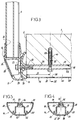
La figure 1 montre, en coupe transversale, une
dalle de balcon 1 dont le bord avant 2 forme le "nez de
dalle". La dalle de balcon 1 reçoit un garde-corps,
désigné dans son ensemble par le repère 3, qui comprend
des barreaux-supports rectilignes 4 disposés à
intervalles, dont les sommets supportent une main-courante
5. Le garde-corps 3 comprend encore un remplissage 6,
monté entre une lisse supérieure 7 et une lisse inférieure
8 qui sont, l'une et l'autre, fixées aux barreaux-supports
4 par des pièces de liaison appropriées, respectivement 9
et 10. De manière bien connue, les barreaux-supports 4, la
main-courante 5 et les lisses 7 et 8 sont constitués par
des profilés en alliage d'aluminium. Dans le cas
particulier de la figure 1, les barreaux-supports 4 sont
fixés verticalement, et situés juste en avant du
remplissage 6, lui-même placé dans le plan vertical
passant par le nez de dalle 2. Chaque barreau-support 4
est fixé sous la dalle 1, au moyen d'un dispositif de
fixation sous dalle désigné dans son ensemble par 11 et
décrit en détail ci-après, la base de ce barreau-support 4
se situant ainsi juste devant le nez de dalle 2.Figure 1 shows, in cross section, a
Comme l'illustre la figure 2, le même dispositif
de fixation sous dalle 11 s'applique aussi à un barreau-support
4 légèrement incliné sur la verticale, la base du
barreau-support 4 étant déportée vers l'avant de manière à
permettre la fixation d'une gouttière 12 contre le nez de
dalle 2. Dans ce dernier cas, le remplissage 6 du garde-corps
reste situé dans un plan vertical passant par le nez
de dalle 2, la lisse inférieure 8 de ce remplissage 6
étant raccordée à chaque barreau-support 4 par une tige de
liaison 13 sensiblement horizontale.As illustrated in Figure 2, the same device
for fixing under
En se référant aux figures 3 et suivantes, on
décrit maintenant le détail du dispositif de fixation sous
dalle 11. Le dispositif 11 se compose principalement d'un
profilé de fixation sous dalle 14, d'une pièce terminale
15 montée à l'avant du profilé 14 et d'un sabot 16 fixé
contre la pièce terminale 15 et recevant la base du
barreau-support 4.Referring to Figures 3 and following, we
now describes the detail of the fixing device under
Le profilé de fixation sous dalle 14 est un
profilé tubulaire, de section symétrique ayant une forme
générale semi-circulaire, sa grande face plane 17 étant
appliquée sous la face inférieure 18 de la dalle 1. Ce
profilé 14 possède des cloisons longitudinales intérieures
19, le divisant intérieurement en deux chambres latérales
20 et 21, et une chambre intermédiaire 22, cette dernière
présentant une section sensiblement carrée - voir figures
4 et 5. Le profilé 14 comporte encore une partie interne
23 relativement massive, percée longitudinalement d'un
canal 24 de section circulaire.The fixing profile under
Le profilé 14 est fixé sous la dalle 1 au moyen
d'une vis verticale 25, située à une distance
prédéterminée D du nez de dalle 2. A l'emplacement de la
vis de fixation 25, la partie massive 23 du profilé 14 est
percée perpendiculairement au canal 24, comme indiqué en
26 (voir figures 3 et 4), de manière à ménager un passage
vertical pour la vis 25. En outre, pour accéder à
l'emplacement de cette vis 25, la région inférieure de la
paroi sensiblement semi-cylindrique 27 du profilé 14 est
découpée localement, comme indiqué en 28, en formant une
"fenêtre" par laquelle la chambre intermédiaire 22 du
profilé 14 s'ouvre vers l'extérieur.The
La pièce terminale 15 possède une surface
extérieure 29 convexe, notamment en calotte sphérique.
Cette pièce terminale 15 s'étend perpendiculairement à la
détection longitudinale du profilé 14. Elle est fixée
contre l'extrémité avant de ce profilé 14.The
Le sabot 16, bien visible aux figures 3 et 6,
possède une embase 30 concave, notamment en couronne
sphérique, complémentaire de la surface extérieure 29 de
la pièce terminale 15. La partie supérieure du sabot 16
forme un logement 31 ouvert vers le haut, recevant la base
du barreau-support 4 qui s'y trouve immobilisée au moyen
d'un dispositif à coin de blocage connu en soi (non
représenté).
L'embase concave 30 du sabot 16 présente, en son
milieu, une ouverture en boutonnière 32 prévue pour être
traversée par une vis de fixation 33, qui traverse aussi
la pièce terminale 15 et qui est introduite et serrée dans
le canal 24 du profilé 14. Dans sa partie antérieure,
l'embase 30 du sabot 16 comporte une ouverture
rectangulaire 34, permettant l'accès à la tête de la vis
de fixation 33.The
Le montage et le réglage du dispositif de fixation
sous dalle 11, précédemment décrit, s'effectuent comme
suit :Installation and adjustment of the fixing device
under
Le profilé 14 est fixé sous la dalle 1 au moyen de
la vis 25. Dans le cas d'un barreau-support 4 vertical
(figures 1 et 3), l'extrémité avant du profilé de fixation
sous dalle 14 est positionnée pratiquement au droit du nez
de dalle 2. Dans le cas d'un barreau-support 4 incliné
(figure 2), l'extrémité avant du profilé 14 est, au
contraire, positionnée en avant du nez de dalle 2. Cette
extrémité avant du profilé 14 reçoit dans tous les cas la
pièce terminale 15, qui y est fixée au moyen de vis (non
représentées) introduites et serrées dans deux rainures
internes 35 et 36 du profilé 14 - voir figures 4 et 5.The
Le sabot 16 est appliqué, par son embase concave
30, contre la surface extérieure convexe 29 de la pièce
terminale 15. Le serrage de la vis 33 fixe le sabot 16
contre la pièce terminale 15 dans la position relative
désirée, en permettant un réglage selon toutes les
directions de l'espace. En particulier, le sabot 16 peut
ainsi être positionné et immobilisé dans une position
plaçant le barreau-support 4 en position verticale
(figures 1 et 3), ou dans une position plaçant le barreau-support
4 en position inclinée (figure 2).
On notera que, la vis de fixation 33 étant posée à
l'avance, sans être serrée à fond, le sabot 16 est engagé
par son ouverture en boutonnière 32 sur cette vis 33 déjà
en place, ce qui facilite sa mise en place ainsi que le
serrage ultérieur de ladite vis 33. Les opérations de
montage et de réglage du sabot 16 sont ainsi commodément
effectuées par une personne prenant place sur la dalle 1.It will be noted that, the fixing
Le montage et le réglage peuvent être suivis par
la mise en place de caches 37,38 et 39, qui obturent
respectivement la fenêtre 28 du profilé de fixation sous
dalle 14, l'ouverture d'accès 34 du sabot 16 et
l'extrémité postérieure du profilé 14. Les deux vis de
fixation 25 et 33 sont ainsi rendues invisibles, aussi
bien par souci de sécurité que dans un but de protection
contre l'humidité, tout en contribuant à l'esthétique du
dispositif de fixation sous dalle 11.Assembly and adjustment can be followed by
the installation of
Comme le montrent les figures 1 et 2, le profilé
de fixation sous dalle 14 possède, entre la vis de
fixation 25 à la dalle 1 et son extrémité postérieure
obturée par le cache 39, une longueur L qui peut être
relativement importante. La longueur L est déterminée en
fonction des exigences prescrites par les normes en
vigueur dans le pays concerné, et par les contraintes de
résistance du dispositif de fixation, notamment les
caractéristiques de la cheville 40, noyée dans la dalle 1,
qui reçoit la vis de fixation 25. En particulier, un
allongement de la longueur L, donc de la distance entre la
vis 25 et l'extrémité postérieure du profilé 14, permet de
réduire, par un effet de bras de levier facilement
compréhensible, les efforts s'exerçant sur la vis 25 et/ou
sur la cheville 40, sous l'action du poids du garde-corps
3 et des forces extérieures transmises par ce garde-corps.As shown in Figures 1 and 2, the profile
fixing under
Ce dispositif de fixation sous dalle 11 est
applicable à des constructions nouvelles et à des travaux
de rénovation. Il concerne non seulement les dalles de
balcons, sensiblement horizontales, mais aussi les montées
d'escalier avec fixation sous une surface inclinée, la
configuration sphérique de la pièce terminale 15 et du
sabot 16 permettant, dans tous les cas d'application, de
fixer le barreau-support 4 en position verticale ou
sensiblement verticale. Bien entendu, ce dispositif de
fixation sous dalle 11 est applicable, sans modification,
non seulement à un garde-corps à remplissage 6 tel que
décrit mais aussi à un garde-corps à barreaudage. De plus,
l'on ne s'éloignerait pas du cadre de l'invention en
prévoyant, dans les cas où cela s'avèrerait nécessaire,
deux vis de fixation du profilé sous la dalle, au lieu
d'une seule vis, ou en remplaçant cette vis de fixation
par tout moyen équivalent, telle qu'une tige filetée
traversant la dalle de part en part, sur toute son
épaisseur.This fixing device under
Claims (12)
- Device for fixing under a slab (1) for a guardrail support stanchion (4), notably for a balcony guardrail, the said device comprising:a substantially horizontal under-slab fixing profiled member (14), the top part (17) of which is intended to be applied underneath the bottom face (18) of the slab (1) and to be fixed thereto by means of at least one screw (25) or the like, the front end of the profiled member (14) being intended to be situated substantially level with the slab nose (2),an end piece (15) mounted at the front end of the under-slab fixing profile member (14), the end piece (15) having a convex, notably spherical, external surface (29),a shoe (16) having a concave base (30), complementary to the convex surface (29) of the aforementioned end piece (15), and a top part (31) provided for the nesting and fixing of the base of the support stanchion (4), andmeans (32, 33) for fixing the shoe (16), by its concave base (30), against the convex external surface (29) of the said end piece (15), in a relative position corresponding to the required position of the support stanchion (4).
- Device according to Claim 1, characterised in that, in the case of a support stanchion (4) to be fixed vertically, the under-slab fixing profiled member (14) can be positioned so that its front end, and consequently the end piece (15) with a convex surface (29), are situated practically in line with the slab nose (2).
- Device according to Claim 1, characterised in that, in the case of a support stanchion (4) to be fixed in an inclined position, when a gutter (12) is to be positioned in front of the slab nose (2), the under-slab fixing profiled member (14) can be positioned so that its front end, and consequently the end piece (15) with a convex surface (29), are situated in front of the slab nose (2) in order to provide the space required for the gutter (12).
- Device according to any one of Claims I to 3, characterised in that the under-slab fixing profiled member (14) has, between its screw (25) for fixing to the slab (1) and its rear end (39), a length (L) which can be relatively great, adapted to the requirements of the screw fixing (25, 40).
- Device according to any one of Claims 1 to 4, characterised in that the under-slab fixing profiled member (14) has a flat top face (17) intended to be applied against the bottom face (18) of the slab (1).
- Device intended to be applied according to Claim 5, characterised in that the under-slab fixing profiled member (14) is a tubular profiled member having a cross section with a semicircular shape overall.
- Device according to Claim 5 or 6, characterised in that the under-slab fixing profiled member (14) has a relatively solid internal part (23), designed to be perforated vertically (at 26) at the location of the screw or screws (25) for fixing to the slab (1).
- Device according to Claim 7, characterised in that the under-slab fixing profiled member (14) has, in the lower region of its external wall (27), a cutout (28) produced in correspondence with the location of the fixing screw (25), this cutout (28) being able to be closed off by fitting a cover (37).
- Device according to Claim 7 or 8, characterised in that the means of fixing the shoe (16) against the end piece (15) consist of a single fixing screw (33), passing through the said end piece (15) and tightened in a longitudinal channel (24) in the under-slab fixing profile member (14) provided in the relatively solid internal part (23) of this profiled member (14).
- Device according to Claim 9, characterised in that the concave base (30) of the shoe (16) has, at its middle, a slot-shaped opening (32) for fitting the shoe (16) on the fixing screw (33).
- Device according to Claim 9 or 10, characterised in that the base (30) of the shoe (16) has, in its front part, an opening (34) affording access to the fixing screw (33), the opening (34) being able to be closed off by fitting a cover (38).
- Device according to any one of Claims 1 to 11, characterised in that the top part of the shoe (16) has a housing (31) open upwards, intended to receive the base of the support stanchion (4).
Applications Claiming Priority (2)
| Application Number | Priority Date | Filing Date | Title |
|---|---|---|---|
| FR9503160 | 1995-03-10 | ||
| FR9503160A FR2731454B1 (en) | 1995-03-10 | 1995-03-10 | SLAB FIXING DEVICE FOR GUARDRAIL SUPPORT BAR |
Publications (2)
| Publication Number | Publication Date |
|---|---|
| EP0731236A1 EP0731236A1 (en) | 1996-09-11 |
| EP0731236B1 true EP0731236B1 (en) | 1999-08-04 |
Family
ID=9477161
Family Applications (1)
| Application Number | Title | Priority Date | Filing Date |
|---|---|---|---|
| EP96420058A Expired - Lifetime EP0731236B1 (en) | 1995-03-10 | 1996-02-22 | Fastening device under floors for the supporting post of balustrades |
Country Status (4)
| Country | Link |
|---|---|
| EP (1) | EP0731236B1 (en) |
| AT (1) | ATE182947T1 (en) |
| DE (1) | DE69603523T2 (en) |
| FR (1) | FR2731454B1 (en) |
Cited By (1)
| Publication number | Priority date | Publication date | Assignee | Title |
|---|---|---|---|---|
| EP3056632A1 (en) | 2015-02-14 | 2016-08-17 | Klaus Peter Abel | Edging for balcony and terrace floors |
Families Citing this family (3)
| Publication number | Priority date | Publication date | Assignee | Title |
|---|---|---|---|---|
| GB9705307D0 (en) * | 1997-03-14 | 1997-04-30 | Ultraframe Plc | Coservatory roofs |
| DE102004014071A1 (en) * | 2004-03-23 | 2005-10-20 | Manfred Richard Dachbau Gmbh | Edging device for fitting on balconies has single retaining elements and sheet metal guttering running crosswise to the longitudinal axes of the retaining elements |
| EP3812531B1 (en) | 2019-10-22 | 2024-05-01 | Hertkorn, Regina | Profile system for holding a flat element |
Family Cites Families (6)
| Publication number | Priority date | Publication date | Assignee | Title |
|---|---|---|---|---|
| DE1936522A1 (en) * | 1968-09-12 | 1970-08-27 | Andersson Sven Lennart | Device for attaching a railing post |
| FR2316410A1 (en) * | 1975-06-30 | 1977-01-28 | Lelorieux Michel | Adjustable equipment support plinth - has flat base and hollow concave walled casing containing convex plates clamping support member by bolt traversing hole in casing |
| DE3702128C2 (en) * | 1987-01-24 | 1996-10-17 | Sks Stakusit Kunststoff Gmbh | Bracket for alignable fastening of the posts of a balcony railing |
| DE4304737A1 (en) * | 1993-02-12 | 1994-08-18 | Mark Tainer Maerkische Stahl U | Fastening element for a railing structure |
| DE4324602A1 (en) * | 1993-07-22 | 1995-01-26 | Werzalit Ag & Co | Post-retaining means for front-attachment balcony railings |
| DE9419270U1 (en) * | 1994-01-17 | 1995-01-26 | Koemmerling Kunststoff | Fastening device for balcony railings |
-
1995
- 1995-03-10 FR FR9503160A patent/FR2731454B1/en not_active Expired - Fee Related
-
1996
- 1996-02-22 EP EP96420058A patent/EP0731236B1/en not_active Expired - Lifetime
- 1996-02-22 AT AT96420058T patent/ATE182947T1/en not_active IP Right Cessation
- 1996-02-22 DE DE69603523T patent/DE69603523T2/en not_active Expired - Fee Related
Cited By (3)
| Publication number | Priority date | Publication date | Assignee | Title |
|---|---|---|---|---|
| EP3056632A1 (en) | 2015-02-14 | 2016-08-17 | Klaus Peter Abel | Edging for balcony and terrace floors |
| DE102015001891A1 (en) | 2015-02-14 | 2016-08-18 | Klaus Peter Abel | Edging for balcony and terrace floors |
| DE102015001891B4 (en) * | 2015-02-14 | 2016-09-15 | Klaus Peter Abel | Edging for balcony and terrace floors |
Also Published As
| Publication number | Publication date |
|---|---|
| ATE182947T1 (en) | 1999-08-15 |
| DE69603523T2 (en) | 1999-11-25 |
| FR2731454A1 (en) | 1996-09-13 |
| FR2731454B1 (en) | 1997-04-25 |
| EP0731236A1 (en) | 1996-09-11 |
| DE69603523D1 (en) | 1999-09-09 |
Similar Documents
| Publication | Publication Date | Title |
|---|---|---|
| FR2694952A1 (en) | System for fixing a curtain wall stiffener on a building element. | |
| EP0170597A1 (en) | Cornice for bridges | |
| EP0731236B1 (en) | Fastening device under floors for the supporting post of balustrades | |
| EP1561864A1 (en) | Assembly device for two modules of precast concrete road barriers | |
| EP0651112B1 (en) | Modular railing with horizontal or inclined rails | |
| EP0651110B1 (en) | Immobilization device of a vertical stiffener of railings opposing a floor support | |
| EP1052344B1 (en) | Kit for mounting a straight stairway and mounting method using it | |
| EP0651097B1 (en) | Balustrade bars and balustrade rail assembly | |
| FR2633319A2 (en) | Improved crash barrier | |
| FR2895003A1 (en) | Balustrade stud for e.g. scaffolding floor of building, has bracket arranged to receive, support and retain corresponding part of sill in bracket so that each sill occupies horizontal position of stud with respect to another sill | |
| FR2947851A1 (en) | Safety balustrade forming device for terraced roof of building, has rail fixed at upper ends of bent parts of posts, and studs for allowing fixation of panels, where panels are inclined with respect to horizontal in fixation position | |
| FR2833630A1 (en) | Wooden crash barrier comprises log with square mortise receiving rigidifying support element which receives connecting sleeve at each end engaging element of another log | |
| FR2717196A1 (en) | Wooden crash barrier for roads | |
| FR2781510A1 (en) | Support for acoustic road screen has parallel uprights with threaded clamping rods | |
| FR2887271A1 (en) | Balustrade installation device for use in e.g. curb, has hollow anchoring part, square in shape, with reinforcement in thickness of connecting zone of branches, which are orthogonal, where one branch carries gripping unit | |
| FR2960576A1 (en) | Staircase i.e. single string-board staircase, has stair stringer comprising slit that is provided with invisible fittings arranged to assure support and fixation of step, where slit is arranged on entire or part of height of stringer | |
| FR2819861A1 (en) | Fastening assembly for bar end to support e.g. for safety railing post comprises sole plate and shoe with adjustable fixings | |
| FR2651811A1 (en) | Metal barrier with vertical railings | |
| EP2492414B1 (en) | Modular guardrail with adjustment device | |
| WO2004102501A1 (en) | Protective device which is designed to enclose a structure such as a swimming pool | |
| FR2852987A1 (en) | Railing, has two posts, each constituting two wing shaped corners that are spaced apart and fix fillers e.g. top rail, in plane between posts | |
| FR2637635A1 (en) | Improved guardrail and device allowing it to be secured in the ground | |
| FR2861776A1 (en) | Support bar for balustrade, has profile including grooves that allow fixation of filling units between successive support-bars, and base mounted on clamp shoe for fixation at balcony pave | |
| FR2718773A1 (en) | Assembly of decorative bars on guard hand rails | |
| FR2877682A1 (en) | Adjusting device for e.g. door, has movable lift-off hinge with end comprising notched convex cylindrical side clamped against notched concave cylindrical sides of lateral edge of door leaf |
Legal Events
| Date | Code | Title | Description |
|---|---|---|---|
| PUAI | Public reference made under article 153(3) epc to a published international application that has entered the european phase |
Free format text: ORIGINAL CODE: 0009012 |
|
| AK | Designated contracting states |
Kind code of ref document: A1 Designated state(s): AT BE CH DE DK ES GB GR IT LI NL SE |
|
| 17P | Request for examination filed |
Effective date: 19961015 |
|
| GRAG | Despatch of communication of intention to grant |
Free format text: ORIGINAL CODE: EPIDOS AGRA |
|
| GRAG | Despatch of communication of intention to grant |
Free format text: ORIGINAL CODE: EPIDOS AGRA |
|
| GRAH | Despatch of communication of intention to grant a patent |
Free format text: ORIGINAL CODE: EPIDOS IGRA |
|
| 17Q | First examination report despatched |
Effective date: 19981222 |
|
| GRAH | Despatch of communication of intention to grant a patent |
Free format text: ORIGINAL CODE: EPIDOS IGRA |
|
| GRAA | (expected) grant |
Free format text: ORIGINAL CODE: 0009210 |
|
| AK | Designated contracting states |
Kind code of ref document: B1 Designated state(s): AT BE CH DE DK ES GB GR IT LI NL SE |
|
| PG25 | Lapsed in a contracting state [announced via postgrant information from national office to epo] |
Ref country code: SE Free format text: THE PATENT HAS BEEN ANNULLED BY A DECISION OF A NATIONAL AUTHORITY Effective date: 19990804 Ref country code: NL Free format text: LAPSE BECAUSE OF FAILURE TO SUBMIT A TRANSLATION OF THE DESCRIPTION OR TO PAY THE FEE WITHIN THE PRESCRIBED TIME-LIMIT Effective date: 19990804 Ref country code: IT Free format text: LAPSE BECAUSE OF FAILURE TO SUBMIT A TRANSLATION OF THE DESCRIPTION OR TO PAY THE FEE WITHIN THE PRESCRIBED TIME-LIMIT;WARNING: LAPSES OF ITALIAN PATENTS WITH EFFECTIVE DATE BEFORE 2007 MAY HAVE OCCURRED AT ANY TIME BEFORE 2007. THE CORRECT EFFECTIVE DATE MAY BE DIFFERENT FROM THE ONE RECORDED. Effective date: 19990804 Ref country code: GR Free format text: LAPSE BECAUSE OF NON-PAYMENT OF DUE FEES Effective date: 19990804 Ref country code: GB Free format text: LAPSE BECAUSE OF FAILURE TO SUBMIT A TRANSLATION OF THE DESCRIPTION OR TO PAY THE FEE WITHIN THE PRESCRIBED TIME-LIMIT Effective date: 19990804 Ref country code: ES Free format text: THE PATENT HAS BEEN ANNULLED BY A DECISION OF A NATIONAL AUTHORITY Effective date: 19990804 Ref country code: AT Free format text: LAPSE BECAUSE OF FAILURE TO SUBMIT A TRANSLATION OF THE DESCRIPTION OR TO PAY THE FEE WITHIN THE PRESCRIBED TIME-LIMIT Effective date: 19990804 |
|
| REF | Corresponds to: |
Ref document number: 182947 Country of ref document: AT Date of ref document: 19990815 Kind code of ref document: T |
|
| REG | Reference to a national code |
Ref country code: CH Ref legal event code: EP |
|
| REF | Corresponds to: |
Ref document number: 69603523 Country of ref document: DE Date of ref document: 19990909 |
|
| PG25 | Lapsed in a contracting state [announced via postgrant information from national office to epo] |
Ref country code: DK Free format text: LAPSE BECAUSE OF FAILURE TO SUBMIT A TRANSLATION OF THE DESCRIPTION OR TO PAY THE FEE WITHIN THE PRESCRIBED TIME-LIMIT Effective date: 19991104 |
|
| NLV1 | Nl: lapsed or annulled due to failure to fulfill the requirements of art. 29p and 29m of the patents act | ||
| GBV | Gb: ep patent (uk) treated as always having been void in accordance with gb section 77(7)/1977 [no translation filed] |
Effective date: 19990804 |
|
| PG25 | Lapsed in a contracting state [announced via postgrant information from national office to epo] |
Ref country code: BE Free format text: LAPSE BECAUSE OF NON-PAYMENT OF DUE FEES Effective date: 20000228 |
|
| PG25 | Lapsed in a contracting state [announced via postgrant information from national office to epo] |
Ref country code: LI Free format text: LAPSE BECAUSE OF NON-PAYMENT OF DUE FEES Effective date: 20000229 Ref country code: CH Free format text: LAPSE BECAUSE OF NON-PAYMENT OF DUE FEES Effective date: 20000229 |
|
| PLBE | No opposition filed within time limit |
Free format text: ORIGINAL CODE: 0009261 |
|
| STAA | Information on the status of an ep patent application or granted ep patent |
Free format text: STATUS: NO OPPOSITION FILED WITHIN TIME LIMIT |
|
| 26N | No opposition filed | ||
| BERE | Be: lapsed |
Owner name: HORIZAL Effective date: 20000228 |
|
| REG | Reference to a national code |
Ref country code: CH Ref legal event code: PL |
|
| PGFP | Annual fee paid to national office [announced via postgrant information from national office to epo] |
Ref country code: DE Payment date: 20050208 Year of fee payment: 10 |
|
| PG25 | Lapsed in a contracting state [announced via postgrant information from national office to epo] |
Ref country code: DE Free format text: LAPSE BECAUSE OF NON-PAYMENT OF DUE FEES Effective date: 20060901 |