EP2492414B1 - Modular guardrail with adjustment device - Google Patents
Modular guardrail with adjustment device Download PDFInfo
- Publication number
- EP2492414B1 EP2492414B1 EP12156201.1A EP12156201A EP2492414B1 EP 2492414 B1 EP2492414 B1 EP 2492414B1 EP 12156201 A EP12156201 A EP 12156201A EP 2492414 B1 EP2492414 B1 EP 2492414B1
- Authority
- EP
- European Patent Office
- Prior art keywords
- handrail
- bars
- vertical
- strip
- support bar
- Prior art date
- Legal status (The legal status is an assumption and is not a legal conclusion. Google has not performed a legal analysis and makes no representation as to the accuracy of the status listed.)
- Active
Links
- 230000000295 complement effect Effects 0.000 claims description 3
- 230000000903 blocking effect Effects 0.000 claims 3
- 208000031968 Cadaver Diseases 0.000 description 4
- 238000009434 installation Methods 0.000 description 4
- 238000012986 modification Methods 0.000 description 4
- 230000004048 modification Effects 0.000 description 4
- 230000007547 defect Effects 0.000 description 3
- 230000001681 protective effect Effects 0.000 description 2
- 240000008042 Zea mays Species 0.000 description 1
- 230000004888 barrier function Effects 0.000 description 1
- 239000000470 constituent Substances 0.000 description 1
- 238000010276 construction Methods 0.000 description 1
- 230000005484 gravity Effects 0.000 description 1
- 210000000003 hoof Anatomy 0.000 description 1
- 230000003100 immobilizing effect Effects 0.000 description 1
- 239000005340 laminated glass Substances 0.000 description 1
- 239000002650 laminated plastic Substances 0.000 description 1
- 239000002184 metal Substances 0.000 description 1
- 238000000034 method Methods 0.000 description 1
- 230000000007 visual effect Effects 0.000 description 1
- XLYOFNOQVPJJNP-UHFFFAOYSA-N water Substances O XLYOFNOQVPJJNP-UHFFFAOYSA-N 0.000 description 1
Images


Classifications
-
- E—FIXED CONSTRUCTIONS
- E04—BUILDING
- E04F—FINISHING WORK ON BUILDINGS, e.g. STAIRS, FLOORS
- E04F11/00—Stairways, ramps, or like structures; Balustrades; Handrails
- E04F11/18—Balustrades; Handrails
- E04F11/181—Balustrades
- E04F11/1836—Handrails of balustrades; Connections between handrail members
-
- E—FIXED CONSTRUCTIONS
- E04—BUILDING
- E04F—FINISHING WORK ON BUILDINGS, e.g. STAIRS, FLOORS
- E04F11/00—Stairways, ramps, or like structures; Balustrades; Handrails
- E04F11/18—Balustrades; Handrails
- E04F11/181—Balustrades
- E04F11/1812—Details of anchoring to the wall or floor
-
- E—FIXED CONSTRUCTIONS
- E04—BUILDING
- E04F—FINISHING WORK ON BUILDINGS, e.g. STAIRS, FLOORS
- E04F11/00—Stairways, ramps, or like structures; Balustrades; Handrails
- E04F11/18—Balustrades; Handrails
- E04F11/181—Balustrades
- E04F11/1812—Details of anchoring to the wall or floor
- E04F11/1814—Covers for the base portions of the balustrade posts
-
- E—FIXED CONSTRUCTIONS
- E04—BUILDING
- E04F—FINISHING WORK ON BUILDINGS, e.g. STAIRS, FLOORS
- E04F11/00—Stairways, ramps, or like structures; Balustrades; Handrails
- E04F11/18—Balustrades; Handrails
- E04F11/181—Balustrades
- E04F11/1817—Connections therefor
-
- E—FIXED CONSTRUCTIONS
- E04—BUILDING
- E04F—FINISHING WORK ON BUILDINGS, e.g. STAIRS, FLOORS
- E04F11/00—Stairways, ramps, or like structures; Balustrades; Handrails
- E04F11/18—Balustrades; Handrails
- E04F11/181—Balustrades
- E04F11/1851—Filling panels, e.g. concrete, sheet metal panels
- E04F11/1853—Glass panels
-
- E—FIXED CONSTRUCTIONS
- E04—BUILDING
- E04F—FINISHING WORK ON BUILDINGS, e.g. STAIRS, FLOORS
- E04F11/00—Stairways, ramps, or like structures; Balustrades; Handrails
- E04F11/18—Balustrades; Handrails
- E04F11/181—Balustrades
- E04F11/1817—Connections therefor
- E04F2011/1819—Connections therefor between balustrade posts and horizontal or sloping balustrade members
- E04F2011/1821—Connections therefor between balustrade posts and horizontal or sloping balustrade members between balustrade posts and handrails
-
- E—FIXED CONSTRUCTIONS
- E04—BUILDING
- E04F—FINISHING WORK ON BUILDINGS, e.g. STAIRS, FLOORS
- E04F11/00—Stairways, ramps, or like structures; Balustrades; Handrails
- E04F11/18—Balustrades; Handrails
- E04F11/181—Balustrades
- E04F11/1817—Connections therefor
- E04F2011/1831—Connections therefor between balustrade filling members, e.g. panels, and balustrade posts
-
- E—FIXED CONSTRUCTIONS
- E04—BUILDING
- E04F—FINISHING WORK ON BUILDINGS, e.g. STAIRS, FLOORS
- E04F11/00—Stairways, ramps, or like structures; Balustrades; Handrails
- E04F11/18—Balustrades; Handrails
- E04F2011/1868—Miscellaneous features of handrails not otherwise provided for
- E04F2011/187—Miscellaneous features of handrails not otherwise provided for lengthwise adjustable, e.g. telescopic
Definitions
- the present invention relates, in a general manner, to the technical field of guardrails intended, in the building sector, to be installed at the edge of slabs of balconies or terraces. More particularly, this invention is concerned with a railing of modular structure, provided with an adjusting device.
- the railings of balconies or terraces are, usually, made with support bars at more or less important intervals, the tops of the support bars being interconnected by a horizontal handrail, while at intermediate heights these support bars are also interconnected by one or more horizontal rails.
- the smooth can be sufficiently close together to constitute by themselves a protective barrier.
- These rails may also remain relatively spaced, in which case they receive between them full or perforated filling elements such as panels of metal or laminated glass or plastic, or they are interconnected by a series of vertical bars sufficiently closer together.
- the bases of the support bars are fixed at ground level, for example near the edge of a balcony slab, by means of hooves.
- Each shoe is itself fixed on the slab by means of a screw, advantageously with the interposition of a wedge allowing adjustment of inclination of the support bar.
- the railings do not include any other height adjustment device.
- irregularities or inclinations of the edge of the slab echo to the top of the support bars, creating a lack of horizontality smooth and especially the handrail.
- This problem is posed not only in case of a construction defect on the front edge of the slab, but also in case of desired inclination of a side edge of the slab to facilitate the flow and evacuation of water rain by gravity.
- Guardrails have already been designed with independent adjustment means for the rails and the handrail. This should theoretically allow a horizontal setting of the rails and the handrail.
- Such a solution requires manual interventions at multiple points, at the time of installation of the railing, without guarantee the horizontality and parallelism of the rails and the handrail. This can result in a visual defect of the guardrail, or even a difficulty of setting up a filling panel between two smooth.
- each support bar has at its base a shoe, on which are guided and immobilized two vertical sections to which are fixed the rails and the handrail. It is thus possible to vertically adjust the position of the rails and the handrail, maintaining their spacing and their parallelism, before immobilizing the assembly by means of a locking flange screwed on the shoe and simultaneously tightened against the bases of the two vertical profiles.
- such a railing embodiment does not allow an easy height adjustment and independent of the two sections, since it provides a common locking flange to these two sections.
- the embodiment according to the aforementioned document eliminates any fixed and rigid support bar extending over the height of the railing, replacing such a support bar by two profiles to be fixed on the same low height shoe. This results in a mechanical weakness of the assembly, due to the fact that the guiding of the sections relative to the shoe is made over a very small length, and also to a risk of insufficient tightening of the locking flange against these profiles.
- the handrail is composed of successive elements, of length equal to that of a module.
- the present invention aims to overcome the disadvantages described above, and therefore aims to provide a railing with improved adjustment device, which allows a vertical as well as longitudinal adjustment, maintaining the spacing and parallelism of smooth and handrail, while avoiding to weaken the parts that participate in the mechanical strength of the railing and that undergo and transmit the efforts.
- the invention relates to a modular railing with adjusting device, according to claim 1.
- the two support bars of each module each comprise a lateral vertical groove into which a complementary part belonging to the associated bar is introduced and guided.
- each bar in the set vertical position, comprise at least one locking screw, screwed into a corresponding threaded hole of the bar and adapted to be clamped against the bottom of the groove of the support bar.
- the fastening means of the handrail consist of a connecting piece mounted at the top of each bar, the connecting piece covering the top of the associated support bar in the entire vertical adjustment range of the bar relative to the bar -support.
- a railing formed modules in which the rails and the handrail are integral, these modules giving the possibility of adjusting the horizontality of the handrail by lifting more or less each bar.
- the rails being fixed between the bars, the vertical adjustment thus carried out preserves the spacing and the parallelism between the rails and the handrail.
- the constitution of the railing in initially independent modules, nevertheless interconnected by a common handrail to these modules allows easy longitudinal adjustment at the time of installation of the railing, spacing more or less two adjacent support bars belonging to two consecutive modules, with a large adjustment range which, however, shall not exceed the maximum deviation set by the applicable standards or other safety requirements.
- the guardrail design object of the invention, retains an important and rigid fixed structure constituted by the support bars fixed on the slab by means of the shoes, and it provides a "long" guide of the bars by the grooves extending over the entire height of the support bars, which provides significant mechanical strength, the support bars can absorb and transmit significant effort.
- each single-bar support bar allows vertical adjustment and individual tightening of all the bars, facilitating the installation of the railing, possibly with the use of appropriate shims to temporarily maintain a set position.
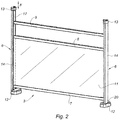
- the guardrail installed on a balcony slab 2 is made from independent modules 3, in the illustrated example several modules 3 placed one after another the along the front edge 4 of the slab 2, and another module 3 placed on a lateral edge 5 of this slab 2.
- the railing comprises vertical support bars 6, horizontal rails 7, 8 and 9 which interconnect the support bars 6 at intermediate heights, and a handrail 10 interconnecting them the vertices of these support bars 6.
- three rails 7, 8 and 9 are provided, with a lower rail 7, an intermediate rail 8, and a top rail 9.
- Filling panels 11 of shape rectangular are mounted between the lower rail 7 and the intermediate rail 8, while the upper rail 9 forms a simple protective bar.
- the bases of the support bars 6 are fixed on the slab 2 by means of shoes 12.
- a module 3 as represented on the figure 2 , comprises two support bars 6 with their respective fixing shoes 12, the three rails 7, 8 and 9 connecting these two support bars 6, and the filling panel 11 which is mounted between the two rails 7 and 8.
- the bars -supports 2 are provided at their vertex respective connecting pieces 13, provided for the attachment of the handrail 10 which is common to all of the modules 3 and therefore does not belong to a particular module.
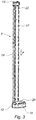
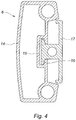
- each support bar 6 comprises a main section 14 which constitutes the body of this support bar, the main section 14 comprising a single vertical lateral groove 15.
- a complementary "T" part 16 belonging to a vertical secondary profile, designated as a bar 17.
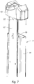
- each support bar 6 At the base of each support bar 6, and as shown in detail in the figure 5 , the lower end of the main section 14 is secured to the fixing shoe 12.
- the latter is intended to be clamped on the slab 2, with the interposition of a setting pad 18 with a toric surface, by means of a screw fixation 19.
- a cover 20 covers the fixing shoe 12, in particular to conceal and protect the fixing screw 19 (the cover 20 having been shown spaced from the shoe 12 for clarity of the drawing).
- the different rails 7, 8 and 9 are all connected, by their ends, to the two bars 17 of a module 3, these two bars 17 being located vis-à-vis.
- the connection between the rails 7, 8, 9 and the bars 17 is made by means of screws (not shown), according to a technique known per se.
- the connecting pieces 13 provided for fixing the handrail 10 are mounted at the top of the bars 17.
- the figure 7 represents the connecting piece 13 spaced from the top of the main profile 14 of the support bar 6, it being understood that in final configuration this connecting piece 13 covers the top of the main section 14.
- the two bars 17 of a module 3 are slid into the grooves 15 of the main profiles 14 of the two support bars 6, and these bars 17 come to a low abutment on the fixing shoes 12 of the support bars 6.
- Each module 3 thus prepared is placed on the slab 2, and is fixed thereto by tightening the fixing screws 19.
- the modules 3 are thus fixed one after the other, the support bar 6 right of a module 3 being located near the support bar 6 left of the next module 3.
- the spacing e between the vertical axis of the right-hand support bar 6 of a module 3 and the vertical axis of the left-hand support bar 6 of the next module 3 is adjustable by the simple choice of the position of installation and fixing of the respective shoes 12 of these two support bars 6.
- the railing is thus adaptable to the length of the slab 2, to compensate for inaccuracies in the length of this slab.
- the connecting pieces 13 are mounted at the top of the bars 17 (unless they have already been previously), and the handrail 10 is itself fixed on these 13.
- the horizontality of the handrail 10 above each module 3, by raising more or less strongly each bar 17 relative to the fixing shoe 12 by sliding of this bar 17 in the vertical groove 15 of the associated main section 14.
- the locking screw 21 is screwed into a corresponding threaded hole 22 of the bar 17, and tightly against the bottom of the groove 15.
- This height adjustment operation makes it possible in particular to compensate for the defects in horizontality or other irregularities of the front edge 4 of the slab 2, but also to compensate for a slight intentional inclination of this slab 2 and its lateral edge 4, inclination to favor the flow and evacuation of rainwater.
Landscapes
- Engineering & Computer Science (AREA)
- Architecture (AREA)
- Civil Engineering (AREA)
- Structural Engineering (AREA)
- Steps, Ramps, And Handrails (AREA)
Description
La présente invention concerne, d'une manière générale, le domaine technique des garde-corps destinés, dans le secteur du bâtiment, à être installés en bordure de dalles de balcons ou de terrasses. Plus particulièrement, cette invention s'intéresse à un garde-corps de structure modulaire, pourvu d'un dispositif de réglage.The present invention relates, in a general manner, to the technical field of guardrails intended, in the building sector, to be installed at the edge of slabs of balconies or terraces. More particularly, this invention is concerned with a railing of modular structure, provided with an adjusting device.
Les garde-corps de balcons ou de terrasses sont, de façon habituelle, réalisés avec des barreaux-supports situés à des intervalles plus ou moins importants, les sommets des barreaux-supports étant reliés entre eux par une main-courante horizontale, tandis qu'à des hauteurs intermédiaires ces barreaux-supports sont aussi reliés entre eux par une ou plusieurs lisses horizontales. Les lisses peuvent être suffisamment rapprochées pour constituer par elles-mêmes une barrière protectrice. Ces lisses peuvent aussi rester relativement écartées, auquel cas elles reçoivent entre elles des éléments de remplissage pleins ou ajourés tels que panneaux en métal ou en verre feuilleté ou en matière synthétique, ou bien encore elles sont reliées entre elles par une série de barreaux verticaux suffisamment rapprochés les uns des autres.The railings of balconies or terraces are, usually, made with support bars at more or less important intervals, the tops of the support bars being interconnected by a horizontal handrail, while at intermediate heights these support bars are also interconnected by one or more horizontal rails. The smooth can be sufficiently close together to constitute by themselves a protective barrier. These rails may also remain relatively spaced, in which case they receive between them full or perforated filling elements such as panels of metal or laminated glass or plastic, or they are interconnected by a series of vertical bars sufficiently closer together.
Les bases des barreaux-supports sont fixées à hauteur du sol, par exemple près du bord d'une dalle de balcon, au moyen de sabots. Chaque sabot est lui-même fixé sur la dalle au moyen d'une vis, avantageusement avec interposition d'une cale permettant un réglage d'inclinaison du barreau-support.The bases of the support bars are fixed at ground level, for example near the edge of a balcony slab, by means of hooves. Each shoe is itself fixed on the slab by means of a screw, advantageously with the interposition of a wedge allowing adjustment of inclination of the support bar.
Dans les réalisations les plus simples, les garde-corps ne comportent aucun autre dispositif de réglage en hauteur. Dans ce cas, des irrégularités ou des inclinaisons du bord de la dalle se répercutent jusqu'au sommet des barreaux-supports, en créant un défaut d'horizontalité des lisses et surtout de la main-courante. Ce problème est posé non seulement en cas de défaut de construction sur le bord avant de la dalle, mais aussi en cas d'inclinaison voulue d'un bord latéral de la dalle afin de faciliter l'écoulement et l'évacuation de l'eau de pluie par gravité.In the simplest embodiments, the railings do not include any other height adjustment device. In this case, irregularities or inclinations of the edge of the slab echo to the top of the support bars, creating a lack of horizontality smooth and especially the handrail. This problem is posed not only in case of a construction defect on the front edge of the slab, but also in case of desired inclination of a side edge of the slab to facilitate the flow and evacuation of water rain by gravity.
On a déjà conçu des garde-corps pourvus de moyens de réglage indépendants pour les lisses et pour la main-courante. Ceci devrait théoriquement permettre une mise à l'horizontale des lisses et de la main-courante. Toutefois, une telle solution nécessite des interventions manuelles en des points multiples, au moment de l'installation du garde-corps, sans garantir l'horizontalité et le parallélisme des lisses et de la main-courante. Il peut en résulter un défaut d'aspect visuel du garde-corps, ou même une difficulté de mise en place d'un panneau de remplissage entre deux lisses.Guardrails have already been designed with independent adjustment means for the rails and the handrail. This should theoretically allow a horizontal setting of the rails and the handrail. However, such a solution requires manual interventions at multiple points, at the time of installation of the railing, without guarantee the horizontality and parallelism of the rails and the handrail. This can result in a visual defect of the guardrail, or even a difficulty of setting up a filling panel between two smooth.
Dans une réalisation de garde-corps particulière, décrite par le brevet
Comme on le conçoit, une telle réalisation de garde-corps ne permet pas un réglage en hauteur aisé et indépendant des deux profilés, puisqu'elle prévoit une bride de blocage commune à ces deux profilés.As conceived, such a railing embodiment does not allow an easy height adjustment and independent of the two sections, since it provides a common locking flange to these two sections.
De plus, la réalisation selon le document précité supprime tout barreau-support fixe et rigide s'étendant sur la hauteur du garde-corps, en remplaçant un tel barreau-support par deux profilés à fixer sur un même sabot de faible hauteur. Il en résulte une faiblesse mécanique de l'ensemble, due au fait que le guidage des profilés relativement au sabot se fait sur une longueur très faible, et aussi à un risque de serrage insuffisant de la bride de blocage contre ces profilés.In addition, the embodiment according to the aforementioned document eliminates any fixed and rigid support bar extending over the height of the railing, replacing such a support bar by two profiles to be fixed on the same low height shoe. This results in a mechanical weakness of the assembly, due to the fact that the guiding of the sections relative to the shoe is made over a very small length, and also to a risk of insufficient tightening of the locking flange against these profiles.
Par ailleurs, même si elle permet un certain ajustement en hauteur, la solution ici évoquée rend impossible tout réglage longitudinal, les deux profilés possédant un écart horizontal fixe du fait qu'ils sont guidés sur un sabot commun. Or il est important, lors de l'installation d'un garde-corps, de pouvoir ajuster celui-ci à la longueur effective de la dalle de balcon et/ou de pouvoir compenser des écarts ou erreurs de dimensions horizontales.Moreover, even if it allows a certain adjustment in height, the solution mentioned here makes impossible any longitudinal adjustment, the two sections having a fixed horizontal gap because they are guided on a common shoe. However, it is important, when installing a railing, to be able to adjust it to the effective length of the balcony slab and / or to be able to compensate for differences or errors in horizontal dimensions.
Un système de garde-corps modulaire assez similaire au précédent est décrit dans le document de
De plus, dans ce dernier document, la main-courante est composée d'éléments successifs, de longueur égale à celle d'un module.Moreover, in this last document, the handrail is composed of successive elements, of length equal to that of a module.
La présente invention vise à remédier aux inconvénients ci-dessus exposés, et elle a donc pour but de fournir un garde-corps avec dispositif de réglage perfectionné, qui permette un ajustement aussi bien vertical que longitudinal, en conservant l'espacement et le parallélisme des lisses et de la main-courante, tout en évitant d'affaiblir les parties qui participent à la résistance mécanique du garde-corps et qui subissent et transmettent les efforts.The present invention aims to overcome the disadvantages described above, and therefore aims to provide a railing with improved adjustment device, which allows a vertical as well as longitudinal adjustment, maintaining the spacing and parallelism of smooth and handrail, while avoiding to weaken the parts that participate in the mechanical strength of the railing and that undergo and transmit the efforts.
A cet effet, l'invention a pour objet un garde-corps modulaire avec dispositif de réglage, selon la revendication 1.For this purpose, the invention relates to a modular railing with adjusting device, according to claim 1.
Dans une forme de réalisation préférée, les deux barreaux-supports de chaque module comportent, chacun, une rainure verticale latérale, dans laquelle est introduite et guidée une partie complémentaire appartenant à la barrette associée.In a preferred embodiment, the two support bars of each module each comprise a lateral vertical groove into which a complementary part belonging to the associated bar is introduced and guided.
Les moyens de blocage de chaque barrette, dans la position verticale réglée, comprennent au moins une vis de blocage, vissée dans un trou taraudé correspondant de la barrette et prévue pour être serrée contre le fond de la rainure du barreau-support.The locking means of each bar, in the set vertical position, comprise at least one locking screw, screwed into a corresponding threaded hole of the bar and adapted to be clamped against the bottom of the groove of the support bar.
Avantageusement, les moyens de fixation de la main-courante sont constitués par une pièce de liaison montée au sommet de chaque barrette, la pièce de liaison coiffant le sommet du barreau-support associé dans toute la plage de réglage vertical de la barrette relativement au barreau-support.Advantageously, the fastening means of the handrail consist of a connecting piece mounted at the top of each bar, the connecting piece covering the top of the associated support bar in the entire vertical adjustment range of the bar relative to the bar -support.
Ainsi, il est réalisé un garde-corps formé de modules, dans lesquels les lisses et la main-courante sont solidaires, ces modules donnant la possibilité de régler l'horizontalité de la main-courante en soulevant plus ou moins chaque barrette. Les lisses étant fixées entre les barrettes, le réglage vertical ainsi effectué préserve l'espacement et le parallélisme entre les lisses et la main-courante. De plus, la constitution du garde-corps en modules initialement indépendants, néanmoins reliés entre eux par une main-courante commune à ces modules, permet un réglage longitudinal aisé au moment de l'installation du garde-corps, en espaçant plus ou moins deux barreaux-supports adjacents appartenant à deux modules consécutifs, avec une amplitude de réglage importante qui toutefois ne doit pas excéder l'écart maximum fixé par les normes ou autres prescriptions de sécurité applicables.Thus, it is made a railing formed modules, in which the rails and the handrail are integral, these modules giving the possibility of adjusting the horizontality of the handrail by lifting more or less each bar. The rails being fixed between the bars, the vertical adjustment thus carried out preserves the spacing and the parallelism between the rails and the handrail. In addition, the constitution of the railing in initially independent modules, nevertheless interconnected by a common handrail to these modules, allows easy longitudinal adjustment at the time of installation of the railing, spacing more or less two adjacent support bars belonging to two consecutive modules, with a large adjustment range which, however, shall not exceed the maximum deviation set by the applicable standards or other safety requirements.
La conception de garde-corps, objet de l'invention, conserve une structure fixe importante et rigide, constituée par les barreaux-supports fixés sur la dalle par l'intermédiaire des sabots, et elle prévoit un guidage « long » des barrettes par les rainures s'étendant sur toute la hauteur des barreaux-supports, ce qui offre une résistance mécanique importante, les barreaux-supports pouvant absorber et transmettre des efforts conséquents.The guardrail design, object of the invention, retains an important and rigid fixed structure constituted by the support bars fixed on the slab by means of the shoes, and it provides a "long" guide of the bars by the grooves extending over the entire height of the support bars, which provides significant mechanical strength, the support bars can absorb and transmit significant effort.
L'association de chaque barreau-support à une seule barrette permet un réglage vertical et un serrage individuels de toutes les barrettes, facilitant les opérations d'installation du garde-corps, éventuellement avec utilisation de cales appropriées pour maintenir provisoirement une position réglée.The combination of each single-bar support bar allows vertical adjustment and individual tightening of all the bars, facilitating the installation of the railing, possibly with the use of appropriate shims to temporarily maintain a set position.
Un module constitutif d'un garde-corps modulaire tel que précédemment défini, est composé de :
- deux barreaux-supports verticaux espacés, pourvus chacun à sa base d'un sabot de fixation,
- deux barrettes verticales respectivement guidées verticalement sur les deux barreaux-supports, les deux barrettes étant situées en vis-à-vis,
- au moins deux lisses horizontales reliant les deux barrettes,
- de préférence, un élément de remplissage ou une série de barreaux présents entre les lisses,
- des moyens de fixation d'une main-courante, portés par les sommets respectifs des deux barrettes, et
- des moyens de blocage de chaque barrette, relativement au barreau-support associé, dans une position verticale voulue.
- two spaced vertical support bars, each provided at its base with a fixing shoe,
- two vertical bars respectively guided vertically on the two support bars, the two bars being located vis-à-vis,
- at least two horizontal rails connecting the two bars,
- preferably, a filling element or a series of bars present between the rails,
- fastening means of a handrail, carried by the respective vertices of the two bars, and
- locking means of each bar relative to the associated support bar, in a desired vertical position.
L'invention sera mieux comprise à l'aide de la description qui suit, en référence au dessin schématique annexé représentant, à titre d'exemple, une forme de réalisation de ce garde-corps modulaire avec dispositif de réglage :
-
Figure 1 est une vue d'ensemble, en perspective, d'un garde-corps modulaire conforme à la présente invention ; -
Figure 2 représente, en perspective, un module du garde-corps de lafigure 1 ; -
Figure 3 est une vue en perspective d'un barreau-support de ce garde-corps ; -
Figure 4 est une section horizontale du barreau-support de lafigure 3 ; -
Figure 5 montre le détail de la base du barreau-support, avec son sabot de fixation ; -
Figure 6 montre un autre détail, dans la zone de liaison des lisses avec les barrettes ; -
Figure 7 montre le détail du sommet d'un barreau-support, avec la pièce de liaison prévue pour recevoir la main-courante.
-
Figure 1 is an overview, in perspective, of a modular railing according to the present invention; -
Figure 2 represents, in perspective, a module of the railing of thefigure 1 ; -
Figure 3 is a perspective view of a support bar of this railing; -
Figure 4 is a horizontal section of the support bar of thefigure 3 ; -
Figure 5 shows the detail of the base of the support bar, with its fixing shoe; -
Figure 6 shows another detail, in the zone of connection of the smooth with the bars; -
Figure 7 shows the detail of the top of a support bar, with the connecting piece provided to receive the handrail.
En se référant aux
D'une manière généralement connue, le garde-corps comprend des barreaux-supports 6 verticaux, des lisses horizontales 7, 8 et 9 qui relient entre eux les barreaux-supports 6 à des hauteurs intermédiaires, et une main-courante 10 reliant entre eux les sommets de ces barreaux-supports 6. Dans l'exemple ici illustré, sont prévues trois lisses 7, 8 et 9, avec une lisse inférieure 7, une lisse intermédiaire 8, et une lisse supérieure 9. Des panneaux de remplissage 11 de forme rectangulaire sont montés entre la lisse inférieure 7 et la lisse intermédiaire 8, tandis que la lisse supérieure 9 forme une simple barre de protection. Les bases des barreaux-supports 6 sont fixées sur la dalle 2 au moyen de sabots 12.In a generally known manner, the railing comprises
Un module 3, tel que représenté sur la
Dans le détail, comme le montrent les
A la base de chaque barreau-support 6, et comme le montre en détail la
Comme le montre la
En se référant enfin à la
Au moment du montage du garde-corps, les deux barrettes 17 d'un module 3 sont glissées dans les rainures 15 des profilés principaux 14 des deux barreaux-supports 6, et ces barrettes 17 viennent en butée basse sur les sabots de fixation 12 des barreaux-supports 6.At the time of mounting the railing, the two
Chaque module 3 ainsi préparé est posé sur la dalle 2, et est fixé à celle-ci par serrage des vis de fixation 19. Les modules 3 sont ainsi fixés les uns à la suite des autres, le barreau-support 6 droit d'un module 3 étant situé à proximité du barreau-support 6 gauche du module 3 suivant. L'espacement e entre l'axe vertical du barreau-support 6 droit d'un module 3 et l'axe vertical du barreau-support 6 gauche du module 3 suivant est ajustable par le simple choix de la position de pose et de fixation des sabots 12 respectifs de ces deux barreaux-supports 6. Le garde-corps est ainsi adaptable à la longueur de la dalle 2, pour compenser des imprécisions de longueur de cette dalle.Each
Après une telle mise en place des modules 3, les pièces de liaison 13 sont montées au sommet des barrettes 17 (à moins qu'elles ne l'aient déjà été précédemment), et la main-courante 10 est elle-même fixée sur ces pièces de liaison 13. A ce moment, comme le symbolise la flèche F, il est possible de régler l'horizontalité de la main-courante 10, au-dessus de chaque module 3, en soulevant plus ou moins fortement chaque barrette 17 relativement au sabot de fixation 12 par coulissement de cette barrette 17 dans la rainure verticale 15 du profilé principal 14 associé. Après ajustement de la hauteur de la barrette 17, celle-ci est immobilisée relativement au profilé principal 14 associé, au moyen d'au moins une vis de blocage 21. La vis de blocage 21 est vissée dans un trou taraudé 22 correspondant de la barrette 17, et serrée fortement contre le fond de la rainure 15.After such introduction of the
Les lisses 7, 8, 9 et la main-courante 10 étant solidarisées avec les mêmes barrettes 17, on comprend que lors d'une telle opération de réglage, l'espacement et le parallélisme de toutes les lisses 7, 8, 9 et de la main-courante 10 se trouve préservé.The
Cette opération de réglage en hauteur permet notamment de compenser les défauts d'horizontalité ou autres irrégularités du bord avant 4 de la dalle 2, mais aussi de compenser une légère inclinaison intentionnelle de cette dalle 2 et de son bord latéral 4, inclinaison visant à favoriser l'écoulement et l'évacuation de l'eau de pluie.This height adjustment operation makes it possible in particular to compensate for the defects in horizontality or other irregularities of the front edge 4 of the
On ne s'éloignerait pas du cadre de l'invention, telle que définie dans les revendications annexées :
- par des modifications de détails, concernant par exemple les sections des profilés ou les formes des sabots de fixation et des pièces de liaison avec la main-courante ;
- par une modification du nombre des lisses horizontales ;
- en remplaçant les éléments de remplissage, placés entre ces lisses, par une série de barreaux ;
- en destinant un tel garde-corps non seulement à des balcons, mais aussi à des terrasses, des passerelles, etc.
- by modifications of details, for example concerning the sections of the profiles or the shapes of the fixing shoes and the connecting pieces with the handrail;
- by a modification of the number of horizontal rails;
- replacing the filling elements, placed between these smooth, by a series of bars;
- by appointing such a railing not only to balconies, but also to terraces, footbridges, etc.
Claims (4)
- A modular railing with an adjusting device, comprising support bars (6) disposed at intervals, whose tops are linked to each other by a handrail (10) and which are also linked to each other, at intermediate heights, by horizontal rails (7, 8, 9) capable of receiving therebetween filling elements (11) or a series of vertical bars, characterized in that the railing is constituted by initially independent modules (3), nevertheless linked to each other by the handrail (10), each composed of:- two spaced vertical support bars (6, 14) each provided at its base with a fastening shoe (12),- two vertical strips (17) respectively guided vertically on the two support bars (6, 14), the two strips (17) being located opposite to each other,- at least two horizontal rails (7, 8, 9) linking the two strips (17),- means for fastening (13) the handrail (10), carried by the respective tops of the two strips (17), and- blocking means (21, 22) of each strip (17), relative to the associated support bar (6, 14) in a desired vertical position,the handrail (10) being common to an assembly of modules (3) and not belonging to a particular module.
- The modular railing according to claim 1, characterized in that the two support bars (6, 14) of each module (3) each include a lateral vertical groove (15), in which a complementary portion (16) belonging to the associated strip (17) is introduced and guided.
- The modular railing according to claim 2, characterized in that the blocking means of each strip (17) in the adjusted vertical position comprise at least one blocking screw (21) screwed into a corresponding threaded hole (22) of the strip (17) and intended to be clamped against the bottom of the groove (15) of the support bar (6, 14).
- The modular railing according to any of claims 1 to 3, characterized in that the means for fastening the handrail (10) are constituted by a link part (13) mounted on the top of each strip (17), the link part (13) enclosing the top of the associated support bar (6, 14) in the whole vertical adjusting range of the strip (17) relative to the support bar (6, 14).
Applications Claiming Priority (1)
| Application Number | Priority Date | Filing Date | Title |
|---|---|---|---|
| FR1151418A FR2971805B1 (en) | 2011-02-22 | 2011-02-22 | MODULAR GUARD RAIL WITH ADJUSTING DEVICE, AND MODULE COMPRISING SUCH A GUARD RAIL |
Publications (2)
| Publication Number | Publication Date |
|---|---|
| EP2492414A1 EP2492414A1 (en) | 2012-08-29 |
| EP2492414B1 true EP2492414B1 (en) | 2017-04-19 |
Family
ID=45581795
Family Applications (1)
| Application Number | Title | Priority Date | Filing Date |
|---|---|---|---|
| EP12156201.1A Active EP2492414B1 (en) | 2011-02-22 | 2012-02-20 | Modular guardrail with adjustment device |
Country Status (2)
| Country | Link |
|---|---|
| EP (1) | EP2492414B1 (en) |
| FR (1) | FR2971805B1 (en) |
Families Citing this family (1)
| Publication number | Priority date | Publication date | Assignee | Title |
|---|---|---|---|---|
| CN108222388B (en) * | 2018-02-01 | 2019-11-12 | 温州市旭阳艺术装饰工程有限公司 | A kind of decoration guardrail being easily installed |
Family Cites Families (3)
| Publication number | Priority date | Publication date | Assignee | Title |
|---|---|---|---|---|
| FR2741903B1 (en) * | 1995-12-01 | 1998-02-20 | Mollard Pierre | PORTION OF FENCE AND FENCE INCLUDING AT LEAST TWO OF SUCH PORTIONS |
| NL1007638C2 (en) * | 1997-11-27 | 1999-06-09 | Straatman Bv | Fencing. |
| FR2857395B1 (en) | 2003-07-08 | 2005-09-02 | Technal | SUPPORT PIETEMENT FOR A VERTICAL GARDEN BODY POST |
-
2011
- 2011-02-22 FR FR1151418A patent/FR2971805B1/en not_active Expired - Fee Related
-
2012
- 2012-02-20 EP EP12156201.1A patent/EP2492414B1/en active Active
Also Published As
| Publication number | Publication date |
|---|---|
| FR2971805B1 (en) | 2016-07-01 |
| EP2492414A1 (en) | 2012-08-29 |
| FR2971805A1 (en) | 2012-08-24 |
Similar Documents
| Publication | Publication Date | Title |
|---|---|---|
| EP0170597B1 (en) | Cornice for bridges | |
| EP3492675B1 (en) | Device for attaching slats with rigid mesh panel, kit for attaching slats with rigid mesh panel and concealing fence provided with such a kit | |
| FR3047260B1 (en) | BODY WELDER | |
| EP0651112B1 (en) | Modular railing with horizontal or inclined rails | |
| EP2492414B1 (en) | Modular guardrail with adjustment device | |
| FR2800768A1 (en) | Building facade cantilever bracket assembly and fixing system esp for curtain walling uses solid plates sliding in metal framework members | |
| EP0774032A1 (en) | Adjustable staircase | |
| FR2937353A1 (en) | Photovoltaic covering element i.e. photovoltaic panel, installing device for flat roof, has connection devices that are detachable from one of sides of panels such that panels occupy horizontal usage position and vertical raised position | |
| FR2935406A1 (en) | Telescopic shelter for swimming pool, has sections sliding one in other along sliding direction in successive interlocking relation, and guiding device placed in upper part of each section and constituted of guiding beam and guiding unit | |
| FR3002253A1 (en) | Roof for modular building, has sealing filling plaster provided for one of set of sections, where plaster is arranged with set of sections and tray so as to ensure sealing of water between longitudinal unit and tray | |
| EP2299027B1 (en) | Scaffolding structure, in particular for façade scaffolding | |
| FR3116291A1 (en) | Railing comprising a device for closing off a free space | |
| EP1640529A1 (en) | Security guard rail | |
| EP0731236B1 (en) | Fastening device under floors for the supporting post of balustrades | |
| EP1561864A1 (en) | Assembly device for two modules of precast concrete road barriers | |
| EP0158755B1 (en) | Modular safety walk, especially for servicing cable bearing rocker bogies of rope railway systems | |
| FR2738862A1 (en) | Sectional frame for barrier | |
| FR2637635A1 (en) | Improved guardrail and device allowing it to be secured in the ground | |
| FR2516142A1 (en) | Corner section for scaffolding - has single vertical support leg with angled bearing heel abutting against building | |
| EP2149649A2 (en) | Device for fixing a railing post to a structure | |
| FR2844537A1 (en) | Connection arrangement for interconnecting steps to uprights for forming stairs or footbridge, includes slides accommodated in uprights and having threaded holes that receive screws to fix step reinforcement to upright | |
| FR2934001A1 (en) | Stake i.e. vertical stake, for safety guardrail, has arm including screw for tightening press with acroterion, where screw is provided with shroud at its end arranged between arms, and guard block made of elastomer is integrated to shroud | |
| FR2970018A1 (en) | Railing for use on staircases to prevent accidental fall of users of circulation area/stroll along gap, has cradles securing screws acting on lower edges of modules to place and maintain module in alignment and fix modules to post | |
| FR2671574A1 (en) | Suspended scaffolding cradle-iron (stirrup) and scaffolding module including the said cradle-iron | |
| EP1647648B1 (en) | Connecting device between a corner post and two filler panels for a railing |
Legal Events
| Date | Code | Title | Description |
|---|---|---|---|
| PUAI | Public reference made under article 153(3) epc to a published international application that has entered the european phase |
Free format text: ORIGINAL CODE: 0009012 |
|
| AK | Designated contracting states |
Kind code of ref document: A1 Designated state(s): AL AT BE BG CH CY CZ DE DK EE ES FI FR GB GR HR HU IE IS IT LI LT LU LV MC MK MT NL NO PL PT RO RS SE SI SK SM TR |
|
| AX | Request for extension of the european patent |
Extension state: BA ME |
|
| 17P | Request for examination filed |
Effective date: 20130218 |
|
| 17Q | First examination report despatched |
Effective date: 20160406 |
|
| GRAP | Despatch of communication of intention to grant a patent |
Free format text: ORIGINAL CODE: EPIDOSNIGR1 |
|
| INTG | Intention to grant announced |
Effective date: 20161123 |
|
| GRAS | Grant fee paid |
Free format text: ORIGINAL CODE: EPIDOSNIGR3 |
|
| GRAA | (expected) grant |
Free format text: ORIGINAL CODE: 0009210 |
|
| AK | Designated contracting states |
Kind code of ref document: B1 Designated state(s): AL AT BE BG CH CY CZ DE DK EE ES FI FR GB GR HR HU IE IS IT LI LT LU LV MC MK MT NL NO PL PT RO RS SE SI SK SM TR |
|
| REG | Reference to a national code |
Ref country code: GB Ref legal event code: FG4D Free format text: NOT ENGLISH |
|
| REG | Reference to a national code |
Ref country code: CH Ref legal event code: EP |
|
| REG | Reference to a national code |
Ref country code: AT Ref legal event code: REF Ref document number: 886119 Country of ref document: AT Kind code of ref document: T Effective date: 20170515 |
|
| REG | Reference to a national code |
Ref country code: IE Ref legal event code: FG4D Free format text: LANGUAGE OF EP DOCUMENT: FRENCH |
|
| REG | Reference to a national code |
Ref country code: DE Ref legal event code: R096 Ref document number: 602012031230 Country of ref document: DE |
|
| REG | Reference to a national code |
Ref country code: NL Ref legal event code: MP Effective date: 20170419 |
|
| REG | Reference to a national code |
Ref country code: LT Ref legal event code: MG4D |
|
| REG | Reference to a national code |
Ref country code: AT Ref legal event code: MK05 Ref document number: 886119 Country of ref document: AT Kind code of ref document: T Effective date: 20170419 |
|
| PG25 | Lapsed in a contracting state [announced via postgrant information from national office to epo] |
Ref country code: NL Free format text: LAPSE BECAUSE OF FAILURE TO SUBMIT A TRANSLATION OF THE DESCRIPTION OR TO PAY THE FEE WITHIN THE PRESCRIBED TIME-LIMIT Effective date: 20170419 |
|
| PG25 | Lapsed in a contracting state [announced via postgrant information from national office to epo] |
Ref country code: HR Free format text: LAPSE BECAUSE OF FAILURE TO SUBMIT A TRANSLATION OF THE DESCRIPTION OR TO PAY THE FEE WITHIN THE PRESCRIBED TIME-LIMIT Effective date: 20170419 Ref country code: ES Free format text: LAPSE BECAUSE OF FAILURE TO SUBMIT A TRANSLATION OF THE DESCRIPTION OR TO PAY THE FEE WITHIN THE PRESCRIBED TIME-LIMIT Effective date: 20170419 Ref country code: NO Free format text: LAPSE BECAUSE OF FAILURE TO SUBMIT A TRANSLATION OF THE DESCRIPTION OR TO PAY THE FEE WITHIN THE PRESCRIBED TIME-LIMIT Effective date: 20170719 Ref country code: FI Free format text: LAPSE BECAUSE OF FAILURE TO SUBMIT A TRANSLATION OF THE DESCRIPTION OR TO PAY THE FEE WITHIN THE PRESCRIBED TIME-LIMIT Effective date: 20170419 Ref country code: LT Free format text: LAPSE BECAUSE OF FAILURE TO SUBMIT A TRANSLATION OF THE DESCRIPTION OR TO PAY THE FEE WITHIN THE PRESCRIBED TIME-LIMIT Effective date: 20170419 Ref country code: AT Free format text: LAPSE BECAUSE OF FAILURE TO SUBMIT A TRANSLATION OF THE DESCRIPTION OR TO PAY THE FEE WITHIN THE PRESCRIBED TIME-LIMIT Effective date: 20170419 Ref country code: GR Free format text: LAPSE BECAUSE OF FAILURE TO SUBMIT A TRANSLATION OF THE DESCRIPTION OR TO PAY THE FEE WITHIN THE PRESCRIBED TIME-LIMIT Effective date: 20170720 |
|
| PG25 | Lapsed in a contracting state [announced via postgrant information from national office to epo] |
Ref country code: PL Free format text: LAPSE BECAUSE OF FAILURE TO SUBMIT A TRANSLATION OF THE DESCRIPTION OR TO PAY THE FEE WITHIN THE PRESCRIBED TIME-LIMIT Effective date: 20170419 Ref country code: SE Free format text: LAPSE BECAUSE OF FAILURE TO SUBMIT A TRANSLATION OF THE DESCRIPTION OR TO PAY THE FEE WITHIN THE PRESCRIBED TIME-LIMIT Effective date: 20170419 Ref country code: BG Free format text: LAPSE BECAUSE OF FAILURE TO SUBMIT A TRANSLATION OF THE DESCRIPTION OR TO PAY THE FEE WITHIN THE PRESCRIBED TIME-LIMIT Effective date: 20170719 Ref country code: LV Free format text: LAPSE BECAUSE OF FAILURE TO SUBMIT A TRANSLATION OF THE DESCRIPTION OR TO PAY THE FEE WITHIN THE PRESCRIBED TIME-LIMIT Effective date: 20170419 Ref country code: RS Free format text: LAPSE BECAUSE OF FAILURE TO SUBMIT A TRANSLATION OF THE DESCRIPTION OR TO PAY THE FEE WITHIN THE PRESCRIBED TIME-LIMIT Effective date: 20170419 Ref country code: IS Free format text: LAPSE BECAUSE OF FAILURE TO SUBMIT A TRANSLATION OF THE DESCRIPTION OR TO PAY THE FEE WITHIN THE PRESCRIBED TIME-LIMIT Effective date: 20170819 |
|
| REG | Reference to a national code |
Ref country code: FR Ref legal event code: PLFP Year of fee payment: 7 |
|
| REG | Reference to a national code |
Ref country code: DE Ref legal event code: R097 Ref document number: 602012031230 Country of ref document: DE |
|
| PG25 | Lapsed in a contracting state [announced via postgrant information from national office to epo] |
Ref country code: EE Free format text: LAPSE BECAUSE OF FAILURE TO SUBMIT A TRANSLATION OF THE DESCRIPTION OR TO PAY THE FEE WITHIN THE PRESCRIBED TIME-LIMIT Effective date: 20170419 Ref country code: DK Free format text: LAPSE BECAUSE OF FAILURE TO SUBMIT A TRANSLATION OF THE DESCRIPTION OR TO PAY THE FEE WITHIN THE PRESCRIBED TIME-LIMIT Effective date: 20170419 Ref country code: RO Free format text: LAPSE BECAUSE OF FAILURE TO SUBMIT A TRANSLATION OF THE DESCRIPTION OR TO PAY THE FEE WITHIN THE PRESCRIBED TIME-LIMIT Effective date: 20170419 Ref country code: SK Free format text: LAPSE BECAUSE OF FAILURE TO SUBMIT A TRANSLATION OF THE DESCRIPTION OR TO PAY THE FEE WITHIN THE PRESCRIBED TIME-LIMIT Effective date: 20170419 Ref country code: CZ Free format text: LAPSE BECAUSE OF FAILURE TO SUBMIT A TRANSLATION OF THE DESCRIPTION OR TO PAY THE FEE WITHIN THE PRESCRIBED TIME-LIMIT Effective date: 20170419 |
|
| PLBE | No opposition filed within time limit |
Free format text: ORIGINAL CODE: 0009261 |
|
| STAA | Information on the status of an ep patent application or granted ep patent |
Free format text: STATUS: NO OPPOSITION FILED WITHIN TIME LIMIT |
|
| PG25 | Lapsed in a contracting state [announced via postgrant information from national office to epo] |
Ref country code: IT Free format text: LAPSE BECAUSE OF FAILURE TO SUBMIT A TRANSLATION OF THE DESCRIPTION OR TO PAY THE FEE WITHIN THE PRESCRIBED TIME-LIMIT Effective date: 20170419 Ref country code: SM Free format text: LAPSE BECAUSE OF FAILURE TO SUBMIT A TRANSLATION OF THE DESCRIPTION OR TO PAY THE FEE WITHIN THE PRESCRIBED TIME-LIMIT Effective date: 20170419 |
|
| 26N | No opposition filed |
Effective date: 20180122 |
|
| PGFP | Annual fee paid to national office [announced via postgrant information from national office to epo] |
Ref country code: DE Payment date: 20171229 Year of fee payment: 7 |
|
| PG25 | Lapsed in a contracting state [announced via postgrant information from national office to epo] |
Ref country code: SI Free format text: LAPSE BECAUSE OF FAILURE TO SUBMIT A TRANSLATION OF THE DESCRIPTION OR TO PAY THE FEE WITHIN THE PRESCRIBED TIME-LIMIT Effective date: 20170419 |
|
| REG | Reference to a national code |
Ref country code: CH Ref legal event code: PL |
|
| PG25 | Lapsed in a contracting state [announced via postgrant information from national office to epo] |
Ref country code: MC Free format text: LAPSE BECAUSE OF FAILURE TO SUBMIT A TRANSLATION OF THE DESCRIPTION OR TO PAY THE FEE WITHIN THE PRESCRIBED TIME-LIMIT Effective date: 20170419 Ref country code: MT Free format text: LAPSE BECAUSE OF FAILURE TO SUBMIT A TRANSLATION OF THE DESCRIPTION OR TO PAY THE FEE WITHIN THE PRESCRIBED TIME-LIMIT Effective date: 20170419 |
|
| GBPC | Gb: european patent ceased through non-payment of renewal fee |
Effective date: 20180220 |
|
| REG | Reference to a national code |
Ref country code: IE Ref legal event code: MM4A |
|
| REG | Reference to a national code |
Ref country code: BE Ref legal event code: MM Effective date: 20180228 |
|
| PG25 | Lapsed in a contracting state [announced via postgrant information from national office to epo] |
Ref country code: LI Free format text: LAPSE BECAUSE OF NON-PAYMENT OF DUE FEES Effective date: 20180228 Ref country code: CH Free format text: LAPSE BECAUSE OF NON-PAYMENT OF DUE FEES Effective date: 20180228 Ref country code: LU Free format text: LAPSE BECAUSE OF NON-PAYMENT OF DUE FEES Effective date: 20180220 |
|
| PG25 | Lapsed in a contracting state [announced via postgrant information from national office to epo] |
Ref country code: IE Free format text: LAPSE BECAUSE OF NON-PAYMENT OF DUE FEES Effective date: 20180220 |
|
| PG25 | Lapsed in a contracting state [announced via postgrant information from national office to epo] |
Ref country code: BE Free format text: LAPSE BECAUSE OF NON-PAYMENT OF DUE FEES Effective date: 20180228 Ref country code: GB Free format text: LAPSE BECAUSE OF NON-PAYMENT OF DUE FEES Effective date: 20180220 |
|
| REG | Reference to a national code |
Ref country code: DE Ref legal event code: R119 Ref document number: 602012031230 Country of ref document: DE |
|
| PG25 | Lapsed in a contracting state [announced via postgrant information from national office to epo] |
Ref country code: DE Free format text: LAPSE BECAUSE OF NON-PAYMENT OF DUE FEES Effective date: 20190903 |
|
| PG25 | Lapsed in a contracting state [announced via postgrant information from national office to epo] |
Ref country code: TR Free format text: LAPSE BECAUSE OF FAILURE TO SUBMIT A TRANSLATION OF THE DESCRIPTION OR TO PAY THE FEE WITHIN THE PRESCRIBED TIME-LIMIT Effective date: 20170419 |
|
| PG25 | Lapsed in a contracting state [announced via postgrant information from national office to epo] |
Ref country code: HU Free format text: LAPSE BECAUSE OF FAILURE TO SUBMIT A TRANSLATION OF THE DESCRIPTION OR TO PAY THE FEE WITHIN THE PRESCRIBED TIME-LIMIT; INVALID AB INITIO Effective date: 20120220 Ref country code: PT Free format text: LAPSE BECAUSE OF FAILURE TO SUBMIT A TRANSLATION OF THE DESCRIPTION OR TO PAY THE FEE WITHIN THE PRESCRIBED TIME-LIMIT Effective date: 20170419 |
|
| PG25 | Lapsed in a contracting state [announced via postgrant information from national office to epo] |
Ref country code: MK Free format text: LAPSE BECAUSE OF NON-PAYMENT OF DUE FEES Effective date: 20170419 Ref country code: CY Free format text: LAPSE BECAUSE OF FAILURE TO SUBMIT A TRANSLATION OF THE DESCRIPTION OR TO PAY THE FEE WITHIN THE PRESCRIBED TIME-LIMIT Effective date: 20170419 |
|
| PG25 | Lapsed in a contracting state [announced via postgrant information from national office to epo] |
Ref country code: AL Free format text: LAPSE BECAUSE OF FAILURE TO SUBMIT A TRANSLATION OF THE DESCRIPTION OR TO PAY THE FEE WITHIN THE PRESCRIBED TIME-LIMIT Effective date: 20170419 |
|
| PGFP | Annual fee paid to national office [announced via postgrant information from national office to epo] |
Ref country code: FR Payment date: 20250131 Year of fee payment: 14 |