EP0731051B1 - Einrichtung und Verfahren zur Schwingungsdämpfung an einer Aufzugskabine - Google Patents
Einrichtung und Verfahren zur Schwingungsdämpfung an einer Aufzugskabine Download PDFInfo
- Publication number
- EP0731051B1 EP0731051B1 EP96103184A EP96103184A EP0731051B1 EP 0731051 B1 EP0731051 B1 EP 0731051B1 EP 96103184 A EP96103184 A EP 96103184A EP 96103184 A EP96103184 A EP 96103184A EP 0731051 B1 EP0731051 B1 EP 0731051B1
- Authority
- EP
- European Patent Office
- Prior art keywords
- oscillations
- cage
- guide elements
- motor part
- cabin
- Prior art date
- Legal status (The legal status is an assumption and is not a legal conclusion. Google has not performed a legal analysis and makes no representation as to the accuracy of the status listed.)
- Expired - Lifetime
Links
- 238000000034 method Methods 0.000 title claims description 13
- 238000013016 damping Methods 0.000 title description 11
- 238000007906 compression Methods 0.000 claims abstract 3
- 230000001133 acceleration Effects 0.000 claims description 15
- 230000001105 regulatory effect Effects 0.000 claims description 10
- 230000033228 biological regulation Effects 0.000 claims description 9
- 230000033001 locomotion Effects 0.000 claims description 9
- 230000010355 oscillation Effects 0.000 claims 14
- 108010066057 cabin-1 Proteins 0.000 description 21
- 230000009466 transformation Effects 0.000 description 21
- 238000005259 measurement Methods 0.000 description 14
- 238000013461 design Methods 0.000 description 6
- 238000006073 displacement reaction Methods 0.000 description 5
- 238000012545 processing Methods 0.000 description 5
- 238000013519 translation Methods 0.000 description 4
- 230000008901 benefit Effects 0.000 description 3
- 230000001419 dependent effect Effects 0.000 description 3
- 230000005484 gravity Effects 0.000 description 3
- 230000001629 suppression Effects 0.000 description 3
- 238000000844 transformation Methods 0.000 description 3
- 238000004458 analytical method Methods 0.000 description 2
- 238000004364 calculation method Methods 0.000 description 2
- 238000004891 communication Methods 0.000 description 2
- 238000010586 diagram Methods 0.000 description 2
- 210000002023 somite Anatomy 0.000 description 2
- 230000003068 static effect Effects 0.000 description 2
- 230000008859 change Effects 0.000 description 1
- 230000008094 contradictory effect Effects 0.000 description 1
- 238000012938 design process Methods 0.000 description 1
- 230000000694 effects Effects 0.000 description 1
- 238000005265 energy consumption Methods 0.000 description 1
- 238000005516 engineering process Methods 0.000 description 1
- 238000007667 floating Methods 0.000 description 1
- 230000007257 malfunction Effects 0.000 description 1
- 230000008569 process Effects 0.000 description 1
- 230000004044 response Effects 0.000 description 1
- 238000005070 sampling Methods 0.000 description 1
- 239000000725 suspension Substances 0.000 description 1
- 238000012549 training Methods 0.000 description 1
- 238000012546 transfer Methods 0.000 description 1
Images


Classifications
-
- B—PERFORMING OPERATIONS; TRANSPORTING
- B66—HOISTING; LIFTING; HAULING
- B66B—ELEVATORS; ESCALATORS OR MOVING WALKWAYS
- B66B7/00—Other common features of elevators
- B66B7/02—Guideways; Guides
- B66B7/023—Mounting means therefor
- B66B7/027—Mounting means therefor for mounting auxiliary devices
-
- B—PERFORMING OPERATIONS; TRANSPORTING
- B66—HOISTING; LIFTING; HAULING
- B66B—ELEVATORS; ESCALATORS OR MOVING WALKWAYS
- B66B7/00—Other common features of elevators
- B66B7/02—Guideways; Guides
- B66B7/04—Riding means, e.g. Shoes, Rollers, between car and guiding means, e.g. rails, ropes
- B66B7/041—Riding means, e.g. Shoes, Rollers, between car and guiding means, e.g. rails, ropes including active attenuation system for shocks, vibrations
- B66B7/042—Riding means, e.g. Shoes, Rollers, between car and guiding means, e.g. rails, ropes including active attenuation system for shocks, vibrations with rollers, shoes
-
- B—PERFORMING OPERATIONS; TRANSPORTING
- B66—HOISTING; LIFTING; HAULING
- B66B—ELEVATORS; ESCALATORS OR MOVING WALKWAYS
- B66B7/00—Other common features of elevators
- B66B7/02—Guideways; Guides
- B66B7/04—Riding means, e.g. Shoes, Rollers, between car and guiding means, e.g. rails, ropes
- B66B7/046—Rollers
Definitions
- the invention relates to a device and a method for Vibration damping on a guided on rails Elevator car that can be moved between two end positions you have connected guide elements, transverse to Vibrations of several at the direction of travel Attached inertial sensors measured and to the Regulation of at least one between cabin and Guide elements arranged actuator are used which to the vibrations occurring and opposite to Direction of the vibrations works.
- Cross vibrations act due to unevenness in the Guide rails, as well as by the headwind, as a result of lateral tensile forces transmitted through the pull cables or when the load changes position while driving on the cabin.
- a method is known from US Pat. No. 5,027,925 to dampen such vibrations in an elevator car or known in part of it; after determining the undesirable lateral accelerations are caused by one Vibration damper arranged between the cabin and frame appropriate counterforce is exerted on the cabin.
- this process requires an expensive floating Storage of the cabin in a cabin frame, what next to that high equipment expenditure a very high additional Requires space.
- the force also acts the frame, which is a jerky and striking the same between the guides can.
- Such a system is hardly a control technology manageable.
- the invention is based on the object Vibration damping device and method simplify and at any time a satisfactory damping of the various vibrations acting on the cabin achieve. This task is carried out by the Claims 1, 6 and 8 specified teaching solved.
- the equipment required to carry out the method is low and the fast moving masses are very small. This is also achieved in that all measurement signals of one common rules are supplied and these pro Guide element only acts on a single actuator. In addition, by adjusting the frequency response of the Controller resonances can be suppressed.
- the position feedback for is particularly advantageous Return of the guide elements to the middle position, the position feedback only in the low frequency range is active.
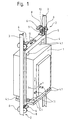
- a cabin 1 is by means of Roller guides 2 guided on rails 3, which are not in one shown shaft are attached.
- the cabin 1 is for passive vibration damping elastic in a cabin frame 4 stored. Rubber springs 4.1 are used, which are relatively stiff be designed to make the occurrence of low frequency Suppress torsional vibrations around the y-axis.
- the Roller guides 2 are on the bottom and top of the side Cabin frame 4 attached. They consist of a stand 5, Actuators 6 and guide elements in the form of two lateral rollers 8 and a middle, rotated by 90 ° to it arranged roller 9.
- Two Position sensors 10 per roller guide 2 each measure the Distance between cabin 1 and rail 3.
- At least three or five Inertia sensors 11 measure those across the cabin 1 occurring vibrations or accelerations.
- the Inertia sensors 11 are preferably in the axis of gravity of the Cabin frame 4 and in pairs far apart arranged to also detect rotations about the z axis can. In addition, wind and rope forces generated vibrations well recorded.
- the data from the Roller guides 2 By processing the measured values, the data from the Roller guides 2 arranged actuators 6, which simultaneous to the vibrations occurring and opposite work towards the direction of the vibrations. So that becomes a Damping of the vibrations acting on the cabin 1 achieved. Vibrations are reduced so that they are on the cabin 1 is no longer in a manner noticeable to the passenger impact.
- Each roller guide 2 is equipped with two actuators 6 equipped. This allows five degrees of freedom or axes of the Cabin 1 can be regulated: displacement in x and y direction, as well as rotation around the x, y and z axes.
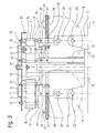
- the linear motor 7 is based on the principle of the moving magnet. It consists of one sheeted and provided with turns 15 stator 16 and a movable motor part 17 designed as a magnet. A magnet 18 is attached to the movable motor part 17. Advantages of the linear motor 7 are its simple controllability, as well as light weight and small moving masses and one great dynamic and static power with small Power consumption.
- roller guide 2 according to the device according to the invention.
- the stand 5 is by means of Fasteners 19 attached to the cabin frame 4.
- Each Roller guide 2 is equipped with two actuators 6 which are each provided with a linear motor 7. One shifts the middle roller 9, the other linear motor 7 the two lateral rollers 8.
- the rollers 8, 9 are by means of axle bolts 20 attached to roller levers 21.
- the roller lever 21 of the Both side rollers 8 are connected via a pull rod 22 connected with each other.
- the roller lever 21 by means Axle pin 23 articulated and low-friction with the stand 5 or the roller lever 21 of the two side rollers 8 by means of Axle pin 24 articulated and low friction with the tie rod 22 connected.
- the pressure springs 26 are each fixed to the outer end 27 of the guide rods 25.
- the guide rods 25 run through a bushing 28 in the roller levers 21, so that the pressure springs 26 on the Outer sides 29 of the roller levers 21 rest and the rollers 8, 9 press against the guide rail 3.
- a mounting plate 30 is by means of fasteners 31 attached to the stand 5 like screws.
- the stators 16 of the Actuators 6 are attached to the fastening elements 32 Screwed mounting plate 30.
- the movable motor part 17th is by means of screws 33 on the roller lever 21 and thus with the Rollers 8, 9 connected. So that the air gap 34 of the Linear motor 7 is preserved, is still a lateral one Guided tour required. This consists of ball-bearing Rolls 35 and is almost frictionless.
- Two brackets 36 enable the mounting of the ball-bearing rollers 35 and form the lateral boundaries of the movable motor part 17. Low-friction storage is necessary to ensure that the Actuator 6 to be able to precisely control the force to be generated.
- the length of the stator 16 of the linear motor 7 determines starting from a middle position 37, the maximum possible inner and outer end positions. The path is limited by elastic stops 38 and 39.
- One variant consists of the movable motor part 17 to connect to the roller lever 21 via a pull-push link.
- the movable motor part 17 is then stored regardless of roller lever 21.
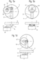
- Fig.5a, 5b and 5c show variants instead of Linear motor 7 to use a rotary drive 43.
- This Drive has a swivel angle of approx. 90 degrees and drives the roller lever 21 with a crank 44 and a pull-push member 45 (Fig.5a) or a flexible traction means 46 (Fig.5b) or with a cam plate 47 (Fig.5c).
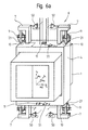
- FIG. 6a and 6b show an elevator car 1 with actuators and sensors in the x k direction and in the y k direction according to the inventive device. To simplify the illustration, the x k and y k directions are each shown separately.
- the system model describes the dynamics of the elevator system in all degrees of freedom mentioned above. This model also takes into account all relevant structural resonances that because of the elasticity between the different masses and arise within the cabin frame 4.
- a controller is used which all degrees of freedom described by the model treated at the same time.
- the methods robust multi-size control (multi-input Multi-Output or MIMO Robust Design).
- MIMO Robust Design multi-size control
- These methods use the existing system model to create a to design observer-based controllers.
- the observer is a dynamic part of the controller and has the task based on the existing measurements (e.g. accelerations different measuring points), all not directly measurable Movement states (e.g. speeds and positions of the different masses) in real time.
- the Regulator for maximum information about the system feature. Based on all states of motion and not only on their measurable part does the controller deliver for everyone Degree of freedom the best answer what the quality of Regulation increased significantly.
- the controller does not excite any of these resonances.
- the model-based control provides the necessary System stability. This would not be the case if the System dynamics in the controller design would not be taken into account.
- the robust controller is designed so that it only works in one certain frequency range takes effect so that it is on unwanted frequency-dependent system dynamics and interference not reacted. This is done without additional filters to have to connect the controller.
- the first goal of the regulator is to suppress the Cabin vibrations in the high frequency range (between 0.9 and 15 Hz) without the regulated elevator outside this Range is worse than the unregulated.
- the controller must ensure that the setting of the Cabin frame 4 with respect to the two guide rails 3 so it is regulated that there is a sufficient damping path at each Roll 8, 9 there. This is particularly important if the cabin 1 is loaded asymmetrically.
- For the first regulatory purpose should be an acceleration or a Speed feedback with inertial sensors 11 are sufficient, with a for the second regulation goal Position feedback is necessary. If the absolute Position of cabin 1 measured and for control could be returned, the second repatriation would have with the first no conflict.
- the first controller has the Measurements from the inertial sensors 11 alone and therefore for the suppression of vibrations responsible.
- the second controller has the Position measurements alone and is for the leadership games Cabin 1 responsible.
- the setpoints of the forces that the first Regulators required by the actuators 6 become the corresponding sizes of the second controller added.
- the Solution to avoid the conflict between the two Regulator based on the fact that for the skew forces responsible for cabin 1 (a non-symmetrical Loading of the cabin, a large lateral rope force, etc.) change much more slowly than the other sources of interference, which cause the cabin vibrations (mainly Rail unevenness and air disturbances).
- Controller contains no non-linearity.
- a non-linearity makes stability analysis very difficult if it is even possible. Because the two returns are simultaneous the method takes both into account Control loops in the stability analysis.
- the controllers are for the system in the cabin coordinate system designed. With the help of different linear
- the measurements are transformed from the coordinate system each sensor to the car body coordinate system.
- Another transformation from the cabin coordinate system too the actuator coordinate systems is for the output of the Force setpoints required.
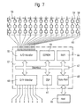
- Fig. 7 shows the controller part of the active system according to the device according to the invention. Since the distances between the Sensors and an analog / digital converter unit 55 relative are long, the measurement signals must be current signals and not are transmitted as voltage signals. The position sensors 10 already deliver their output signals as current. On the other hand the inertial sensors 11 deliver their outputs in the form of Voltage signals. In this case, a voltage / current converter 51 for the output of each inertial sensor 11 necessary. Since the analog / digital converter 55 only Can sense voltage signals becomes an analog Signal processing unit 56 on the part of real-time computer 57 used, which has a channel for each measurement signal. On Channel consists of a current / voltage converter 58, one Anti-aliasing low-pass filter 59, which is used for scanning is necessary, and an ordinary voltage gain 60 to adjust the signal range.
- the core of the real-time computer 57 is the digital one Signal processor 61, which for all mathematical Calculations is responsible. To make the necessary measurements Being able to capture from the hardware becomes a multi-channel Analog / digital converter unit 55 used. For output the force setpoints for the linear motors 7 become one multi-channel digital / analog converter unit 63 used.
- An EEPROM 64 is the entire controller algorithm with all required programs are saved. This program will during commissioning of the active system by one Host computer 65 delivered and to the cabin to be controlled 1 customized. After commissioning, the host computer 65 uncoupled, the one stored on the EEPROM 64 The program stays there until the next calibration is modified or replaced by the host computer 65.
- a RAM 66 is used by the digital signal processor 61 as a memory for the Intermediate values of the calculations used.
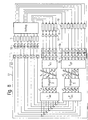
- Figure 8 shows the block diagram for the whole system according to the device according to the invention.
- the real-time computer 57 is programmed in this application to use the Controller algorithm with a certain frequency in real time calculated.
- the execution of all linear transformations as well as the The controller algorithm is calculated by the digital Signal processor 61 performed every sampling period.
Landscapes
- Cage And Drive Apparatuses For Elevators (AREA)
- Lift-Guide Devices, And Elevator Ropes And Cables (AREA)
- Types And Forms Of Lifts (AREA)
- Elevator Control (AREA)
- Vibration Prevention Devices (AREA)
Applications Claiming Priority (3)
| Application Number | Priority Date | Filing Date | Title |
|---|---|---|---|
| CH69495 | 1995-03-10 | ||
| CH69495 | 1995-03-10 | ||
| CH694/95 | 1995-03-10 |
Publications (2)
| Publication Number | Publication Date |
|---|---|
| EP0731051A1 EP0731051A1 (de) | 1996-09-11 |
| EP0731051B1 true EP0731051B1 (de) | 2001-05-23 |
Family
ID=4192985
Family Applications (1)
| Application Number | Title | Priority Date | Filing Date |
|---|---|---|---|
| EP96103184A Expired - Lifetime EP0731051B1 (de) | 1995-03-10 | 1996-03-01 | Einrichtung und Verfahren zur Schwingungsdämpfung an einer Aufzugskabine |
Country Status (11)
| Country | Link |
|---|---|
| US (1) | US5896949A (ja) |
| EP (1) | EP0731051B1 (ja) |
| JP (2) | JPH08245117A (ja) |
| CN (1) | CN1050580C (ja) |
| AT (1) | ATE201380T1 (ja) |
| AU (1) | AU702382B2 (ja) |
| CA (1) | CA2171376C (ja) |
| DE (1) | DE59606928D1 (ja) |
| HK (1) | HK1011340A1 (ja) |
| MY (1) | MY115725A (ja) |
| SG (1) | SG54248A1 (ja) |
Families Citing this family (47)
| Publication number | Priority date | Publication date | Assignee | Title |
|---|---|---|---|---|
| ES2283002T3 (es) * | 1995-06-07 | 2007-10-16 | The Howard Foundation | Carotenoides farmaceuticamente activos. |
| JP4131764B2 (ja) * | 1998-09-01 | 2008-08-13 | 東芝エレベータ株式会社 | エレベータ装置 |
| FI981887A (fi) * | 1998-09-04 | 2000-03-05 | Kone Corp | Hissijärjestely hissikoneiston moottorin lähtömomentin asettamiseksi |
| US6216824B1 (en) * | 1998-12-24 | 2001-04-17 | United Technologies Corporation | Semi-active elevator hitch |
| JP4161063B2 (ja) | 1999-10-22 | 2008-10-08 | 三菱電機株式会社 | エレベータ装置及びエレベータ装置のガイド装置 |
| US6305502B1 (en) * | 1999-12-21 | 2001-10-23 | Otis Elevator Company | Elevator cab floor acceleration control system |
| US6435314B1 (en) * | 2000-03-24 | 2002-08-20 | Otis Elevator Company | Elevator platform stabilization coupler |
| SG89424A1 (en) * | 2000-10-23 | 2002-06-18 | Inventio Ag | Method and system for compensating vibrations in elevator cars |
| JP4413505B2 (ja) * | 2002-03-07 | 2010-02-10 | インベンテイオ・アクテイエンゲゼルシヤフト | エレベータケージの振動を減衰させるための装置 |
| JP4107480B2 (ja) * | 2002-07-29 | 2008-06-25 | 三菱電機株式会社 | エレベータの振動低減装置 |
| SG109535A1 (en) * | 2003-08-14 | 2005-03-30 | Inventio Ag | Electric motor, lift with a cage movable by an electric motor, and lift with a cage and with an electric motor for movement of a guide element relative to the cage |
| EP1507329A1 (de) * | 2003-08-14 | 2005-02-16 | Inventio Ag | Elektromotor, Aufzug mit einer mit einem Elektromotor bewegbaren Kabine und Aufzug mit einer Kabine und mit einem Elektromotor zur Bewegung eines Führungselements relativ zu der Kabine |
| US7141946B2 (en) * | 2003-09-15 | 2006-11-28 | Rockwell Automation Technologies, Inc. | Method and apparatus for providing optimal acceleration feedback |
| DE602004003117T2 (de) * | 2003-12-22 | 2007-05-10 | Inventio Ag, Hergiswil | Steuerungseinheit für die aktive Schwingungsdämpfung der Vibrationen einer Aufzugskabine |
| SG112941A1 (en) * | 2003-12-22 | 2005-07-28 | Inventio Ag | Thermal protection of electromagnetic actuators |
| SG112944A1 (en) * | 2003-12-22 | 2005-07-28 | Inventio Ag | Equipment for vibration damping of a lift cage |
| EP1547957A1 (de) * | 2003-12-22 | 2005-06-29 | Inventio Ag | Einrichtung zur Schwingungsdämpfung an einer Aufzugskabine |
| EP1547955B1 (en) * | 2003-12-22 | 2006-11-08 | Inventio Ag | Controller supervision for active vibration damping of elevator cars |
| EP1547956B1 (de) * | 2003-12-22 | 2007-09-05 | Inventio Ag | Einrichtung und Verfahren zur Schwingungsdämpfung an einer Aufzugskabine |
| MY142882A (en) * | 2003-12-22 | 2011-01-31 | Inventio Ag | Equipment and method for vibration damping of a lift cage |
| EP1547958B1 (en) * | 2003-12-22 | 2007-05-23 | Inventio Ag | Thermal protection of electromagnetic actuators |
| MY138827A (en) * | 2004-02-02 | 2009-07-31 | Inventio Ag | Method for vibration damping at an elevator car |
| MY192706A (en) * | 2004-12-17 | 2022-09-02 | Inventio Ag | Lift installation with a braking device, and method for braking and holding a lift installation |
| JP4800793B2 (ja) * | 2006-02-24 | 2011-10-26 | 三菱電機ビルテクノサービス株式会社 | エレベータの制御装置 |
| KR101080601B1 (ko) * | 2006-12-05 | 2011-11-04 | 미쓰비시덴키 가부시키가이샤 | 엘리베이터 장치 |
| CN101528577B (zh) * | 2006-12-13 | 2011-09-07 | 三菱电机株式会社 | 电梯装置 |
| BRPI0913051B1 (pt) * | 2008-05-23 | 2020-06-23 | Thyssenkrupp Elevator Corporation | Aparelho para amortecer as oscilações de um carro de elevador |
| US8768522B2 (en) * | 2012-05-14 | 2014-07-01 | Mitsubishi Electric Research Laboratories, Inc. | System and method for controlling semi-active actuators |
| EP2864232A4 (en) | 2012-06-20 | 2016-03-02 | Otis Elevator Co | ACTIVE DAMPING OF VERTICAL VIBRATIONS OF AN LIFT CABIN |
| CN102788661B (zh) * | 2012-07-11 | 2014-11-19 | 三洋电梯(珠海)有限公司 | 轿厢重力中心测试仪 |
| WO2014057302A1 (en) * | 2012-10-08 | 2014-04-17 | Otis Elevator Company | Low friction sliding guide shoe for elevator |
| CN104781173B (zh) * | 2012-11-05 | 2017-02-22 | 奥的斯电梯公司 | 惯性测量单元辅助的电梯位置校准 |
| JP6173752B2 (ja) * | 2013-04-10 | 2017-08-02 | 株式会社日立製作所 | 制振装置付きエレベータ |
| JP6295166B2 (ja) * | 2014-08-18 | 2018-03-14 | 株式会社日立製作所 | エレベータ装置及びこれの制振機構調整方法 |
| CN107108171B (zh) * | 2014-12-17 | 2020-05-29 | 因温特奥股份公司 | 用于电梯的减振单元 |
| JP6399404B2 (ja) * | 2015-03-20 | 2018-10-03 | フジテック株式会社 | エレベータ用のかご横揺れ抑制装置及びかご横揺れ抑制方法 |
| US20170008736A1 (en) * | 2015-07-09 | 2017-01-12 | Otis Elevator Company | Active vibration damper for a linear propulsion system of a ropeless elevator |
| CN106477431B (zh) | 2015-09-01 | 2020-01-21 | 奥的斯电梯公司 | 电梯轿厢的轿厢室隔离 |
| JP6158381B1 (ja) * | 2016-03-09 | 2017-07-05 | 東芝エレベータ株式会社 | エレベータ装置 |
| JP2017160005A (ja) * | 2016-03-09 | 2017-09-14 | 東芝エレベータ株式会社 | エレベータ装置 |
| JP6591923B2 (ja) * | 2016-03-30 | 2019-10-16 | 株式会社日立製作所 | エレベーター装置 |
| US10407274B2 (en) | 2016-12-08 | 2019-09-10 | Mitsubishi Electric Research Laboratories, Inc. | System and method for parameter estimation of hybrid sinusoidal FM-polynomial phase signal |
| CN108285081B (zh) | 2017-01-10 | 2021-08-03 | 奥的斯电梯公司 | 升降机轿厢的稳定装置及其控制方法、升降机系统 |
| US10866124B2 (en) | 2017-10-24 | 2020-12-15 | Mitsubishi Electric Research Laboratories, Inc. | Systems and methods for speed estimation of contactless encoder systems |
| CN109095328B (zh) * | 2018-09-28 | 2020-07-31 | 山东富士制御电梯有限公司 | 一种高速电梯轿厢水平振动的减振系统及其控制方法 |
| US11795032B2 (en) * | 2018-11-13 | 2023-10-24 | Otis Elevator Company | Monitoring system |
| US11104545B2 (en) * | 2018-12-10 | 2021-08-31 | Otis Elevator Company | Elevator safety actuator systems |
Family Cites Families (12)
| Publication number | Priority date | Publication date | Assignee | Title |
|---|---|---|---|---|
| FI884380A (fi) * | 1988-09-23 | 1990-03-24 | Kone Oy | Foerfarande och anordning foer daempandet av vibrationer i en hisskorg. |
| JP2728513B2 (ja) * | 1989-08-30 | 1998-03-18 | 株式会社日立製作所 | エレベーター装置 |
| US5322144A (en) * | 1990-07-18 | 1994-06-21 | Otis Elevator Company | Active control of elevator platform |
| US5294757A (en) * | 1990-07-18 | 1994-03-15 | Otis Elevator Company | Active vibration control system for an elevator, which reduces horizontal and rotational forces acting on the car |
| JP2756208B2 (ja) * | 1991-03-13 | 1998-05-25 | オーチス エレベータ カンパニー | 垂直走行中のエレベータかごの水平偏差修正装置 |
| EP0503972B1 (en) * | 1991-03-13 | 1996-05-29 | Otis Elevator Company | Elevator rail profile estimation and elevator control method |
| CA2072240C (en) * | 1991-07-16 | 1998-05-05 | Clement A. Skalski | Elevator horizontal suspensions and controls |
| US5289902A (en) * | 1991-10-29 | 1994-03-01 | Kabushiki Kaisha Toshiba | Elevator |
| JP2616527B2 (ja) * | 1992-01-06 | 1997-06-04 | 株式会社日立製作所 | エレベーター装置及びその制御方法 |
| EP0675066B1 (en) * | 1994-03-31 | 1998-04-29 | Otis Elevator Company | Control system for elevator active vibration control |
| US5652414A (en) * | 1994-08-18 | 1997-07-29 | Otis Elevator Company | Elevator active guidance system having a coordinated controller |
| US5535853A (en) * | 1994-11-14 | 1996-07-16 | Otis Elevator Company | Actuator having a two ended actuator rod movable longitudinally and transversely |
-
1996
- 1996-03-01 DE DE59606928T patent/DE59606928D1/de not_active Expired - Lifetime
- 1996-03-01 AT AT96103184T patent/ATE201380T1/de not_active IP Right Cessation
- 1996-03-01 EP EP96103184A patent/EP0731051B1/de not_active Expired - Lifetime
- 1996-03-07 AU AU47919/96A patent/AU702382B2/en not_active Ceased
- 1996-03-08 CN CN96102730A patent/CN1050580C/zh not_active Expired - Fee Related
- 1996-03-08 CA CA002171376A patent/CA2171376C/en not_active Expired - Fee Related
- 1996-03-08 SG SG1996006131A patent/SG54248A1/en unknown
- 1996-03-08 JP JP8052073A patent/JPH08245117A/ja not_active Withdrawn
- 1996-03-08 US US08/613,168 patent/US5896949A/en not_active Expired - Lifetime
- 1996-03-09 MY MYPI96000878A patent/MY115725A/en unknown
-
1998
- 1998-11-26 HK HK98112337A patent/HK1011340A1/xx not_active IP Right Cessation
-
2008
- 2008-08-15 JP JP2008209253A patent/JP4493709B2/ja not_active Expired - Lifetime
Also Published As
| Publication number | Publication date |
|---|---|
| ATE201380T1 (de) | 2001-06-15 |
| JP2008297127A (ja) | 2008-12-11 |
| DE59606928D1 (de) | 2001-06-28 |
| JP4493709B2 (ja) | 2010-06-30 |
| US5896949A (en) | 1999-04-27 |
| CN1134392A (zh) | 1996-10-30 |
| JPH08245117A (ja) | 1996-09-24 |
| SG54248A1 (en) | 1998-11-16 |
| HK1011340A1 (en) | 1999-07-09 |
| CA2171376C (en) | 2006-06-13 |
| AU702382B2 (en) | 1999-02-18 |
| CA2171376A1 (en) | 1996-09-11 |
| AU4791996A (en) | 1996-09-19 |
| CN1050580C (zh) | 2000-03-22 |
| EP0731051A1 (de) | 1996-09-11 |
| MY115725A (en) | 2003-08-30 |
Similar Documents
| Publication | Publication Date | Title |
|---|---|---|
| EP0731051B1 (de) | Einrichtung und Verfahren zur Schwingungsdämpfung an einer Aufzugskabine | |
| DE3631633C2 (ja) | ||
| DE60103191T2 (de) | In jede Richtung fahrbares Fahrzeug und Verfahren zur Steuerung desselben | |
| DE102004001764B4 (de) | Ausgleich der Reibung in einem Lenksystem eines Fahrzeuges | |
| DE69828348T2 (de) | Einrichtung zur Steuerung der Geschwindigkeit von Aufzügen | |
| DE102011052205A9 (de) | Positionssteuerungssystem für kreuzgekoppelten Betrieb von Fly-By-Wire-Steuersäulen | |
| DE112014001217B4 (de) | Verfahren und System zur Regelung einer Menge von semiaktiven Aktoren, die in einem Aufzug angeordnet sind | |
| DE102011052206A1 (de) | Inaktive Direktantriebs-Steuersäule | |
| DE102017105129A1 (de) | Verfahren zur Steuerung von Schwingungen eines an eine Aufzugkabine angeschlossenen Aufzugkabels | |
| DE19648896A1 (de) | Stanzen-Umführungssteuersystem mit gedämpftem Nachfolger | |
| DE112007003699B4 (de) | Türsteuervorrichtung für einen Aufzug | |
| EP3424136B1 (de) | Linearmotoranordnung für eine aufzugsanlage | |
| DE3819447C2 (ja) | ||
| EP0557541A1 (de) | Regelung mit Vorsteuerung, insbesondere für ein Walzgerüst | |
| EP3672808A1 (de) | Regelung von druckmaschinen mit mehreren hauptantriebsmotoren | |
| EP2052885B1 (de) | Verfahren und System zur Beeinflussung der Bewegung eines in seinen Bewegungsabläufen steuerbaren oder regelbaren Fahrzeugaufbaus eines Kraftfahrzeuges und Fahrzeug | |
| DE102007051218A1 (de) | Verfahren und Regelungssystem/Regelungskomponente zur Bestimmung von dynamischen Nick-, Wank- und/oder Hubachsen | |
| DE19961880A1 (de) | Elektrisches Antriebssystem zur aktiven Schwingungsdämpfung | |
| DE4005194A1 (de) | Vorrichtung zum verhindern des schwankens einer last unter einem traggeruest, insbesondere einer hebebruecke | |
| DE102007049455A1 (de) | Verfahren zum Betreiben einer Druckmaschine | |
| DE19918449A1 (de) | Verfahren und Lasthebesystem zur Feinpositionierung und aktiven Pendeldämpfung von Lasten | |
| EP0720556B1 (de) | Verfahren zur querstabilisierung von schienenfahrzeugen mit gleisbogenabhängiger wagenkastensteuerung | |
| EP1547956B1 (de) | Einrichtung und Verfahren zur Schwingungsdämpfung an einer Aufzugskabine | |
| AT526074B1 (de) | Vorrichtung zur Interaktion eines Benutzers mit einem Simulationsumfeld | |
| DE3021809C2 (de) | Regelungsanordnung zur Schwebeführung eines magnetisch getragenen Schwebefahrzeuges |
Legal Events
| Date | Code | Title | Description |
|---|---|---|---|
| PUAI | Public reference made under article 153(3) epc to a published international application that has entered the european phase |
Free format text: ORIGINAL CODE: 0009012 |
|
| AK | Designated contracting states |
Kind code of ref document: A1 Designated state(s): AT CH DE FR GB LI |
|
| 17P | Request for examination filed |
Effective date: 19970217 |
|
| GRAG | Despatch of communication of intention to grant |
Free format text: ORIGINAL CODE: EPIDOS AGRA |
|
| 17Q | First examination report despatched |
Effective date: 20000517 |
|
| GRAG | Despatch of communication of intention to grant |
Free format text: ORIGINAL CODE: EPIDOS AGRA |
|
| GRAG | Despatch of communication of intention to grant |
Free format text: ORIGINAL CODE: EPIDOS AGRA |
|
| GRAH | Despatch of communication of intention to grant a patent |
Free format text: ORIGINAL CODE: EPIDOS IGRA |
|
| GRAH | Despatch of communication of intention to grant a patent |
Free format text: ORIGINAL CODE: EPIDOS IGRA |
|
| GRAA | (expected) grant |
Free format text: ORIGINAL CODE: 0009210 |
|
| AK | Designated contracting states |
Kind code of ref document: B1 Designated state(s): AT CH DE FR GB LI |
|
| REF | Corresponds to: |
Ref document number: 201380 Country of ref document: AT Date of ref document: 20010615 Kind code of ref document: T |
|
| REG | Reference to a national code |
Ref country code: CH Ref legal event code: EP |
|
| REF | Corresponds to: |
Ref document number: 59606928 Country of ref document: DE Date of ref document: 20010628 |
|
| GBT | Gb: translation of ep patent filed (gb section 77(6)(a)/1977) |
Effective date: 20010618 |
|
| ET | Fr: translation filed | ||
| REG | Reference to a national code |
Ref country code: GB Ref legal event code: IF02 |
|
| PLBE | No opposition filed within time limit |
Free format text: ORIGINAL CODE: 0009261 |
|
| STAA | Information on the status of an ep patent application or granted ep patent |
Free format text: STATUS: NO OPPOSITION FILED WITHIN TIME LIMIT |
|
| 26N | No opposition filed | ||
| PGFP | Annual fee paid to national office [announced via postgrant information from national office to epo] |
Ref country code: AT Payment date: 20100311 Year of fee payment: 15 |
|
| PG25 | Lapsed in a contracting state [announced via postgrant information from national office to epo] |
Ref country code: AT Free format text: LAPSE BECAUSE OF NON-PAYMENT OF DUE FEES Effective date: 20110301 |
|
| PGFP | Annual fee paid to national office [announced via postgrant information from national office to epo] |
Ref country code: FR Payment date: 20130408 Year of fee payment: 18 Ref country code: CH Payment date: 20130327 Year of fee payment: 18 Ref country code: GB Payment date: 20130321 Year of fee payment: 18 Ref country code: DE Payment date: 20130321 Year of fee payment: 18 |
|
| REG | Reference to a national code |
Ref country code: DE Ref legal event code: R119 Ref document number: 59606928 Country of ref document: DE |
|
| REG | Reference to a national code |
Ref country code: CH Ref legal event code: PL |
|
| GBPC | Gb: european patent ceased through non-payment of renewal fee |
Effective date: 20140301 |
|
| REG | Reference to a national code |
Ref country code: FR Ref legal event code: ST Effective date: 20141128 |
|
| REG | Reference to a national code |
Ref country code: DE Ref legal event code: R119 Ref document number: 59606928 Country of ref document: DE Effective date: 20141001 |
|
| PG25 | Lapsed in a contracting state [announced via postgrant information from national office to epo] |
Ref country code: DE Free format text: LAPSE BECAUSE OF NON-PAYMENT OF DUE FEES Effective date: 20141001 Ref country code: CH Free format text: LAPSE BECAUSE OF NON-PAYMENT OF DUE FEES Effective date: 20140331 Ref country code: GB Free format text: LAPSE BECAUSE OF NON-PAYMENT OF DUE FEES Effective date: 20140301 Ref country code: LI Free format text: LAPSE BECAUSE OF NON-PAYMENT OF DUE FEES Effective date: 20140331 Ref country code: FR Free format text: LAPSE BECAUSE OF NON-PAYMENT OF DUE FEES Effective date: 20140331 |