EP1507329A1 - Elektromotor, Aufzug mit einer mit einem Elektromotor bewegbaren Kabine und Aufzug mit einer Kabine und mit einem Elektromotor zur Bewegung eines Führungselements relativ zu der Kabine - Google Patents
Elektromotor, Aufzug mit einer mit einem Elektromotor bewegbaren Kabine und Aufzug mit einer Kabine und mit einem Elektromotor zur Bewegung eines Führungselements relativ zu der Kabine Download PDFInfo
- Publication number
- EP1507329A1 EP1507329A1 EP04018643A EP04018643A EP1507329A1 EP 1507329 A1 EP1507329 A1 EP 1507329A1 EP 04018643 A EP04018643 A EP 04018643A EP 04018643 A EP04018643 A EP 04018643A EP 1507329 A1 EP1507329 A1 EP 1507329A1
- Authority
- EP
- European Patent Office
- Prior art keywords
- electric motor
- primary part
- secondary part
- cabin
- magnetic field
- Prior art date
- Legal status (The legal status is an assumption and is not a legal conclusion. Google has not performed a legal analysis and makes no representation as to the accuracy of the status listed.)
- Withdrawn
Links
- 230000005291 magnetic effect Effects 0.000 claims abstract description 70
- 239000004020 conductor Substances 0.000 claims description 54
- 239000000758 substrate Substances 0.000 claims description 49
- 230000003068 static effect Effects 0.000 claims description 24
- 239000000696 magnetic material Substances 0.000 claims description 4
- 238000004804 winding Methods 0.000 claims 1
- 238000004519 manufacturing process Methods 0.000 description 10
- 239000000463 material Substances 0.000 description 8
- 230000001617 migratory effect Effects 0.000 description 7
- 238000010276 construction Methods 0.000 description 5
- 238000013461 design Methods 0.000 description 4
- 230000000694 effects Effects 0.000 description 4
- 230000008901 benefit Effects 0.000 description 3
- 239000012141 concentrate Substances 0.000 description 3
- 238000011161 development Methods 0.000 description 3
- 230000005294 ferromagnetic effect Effects 0.000 description 3
- 230000004907 flux Effects 0.000 description 3
- 230000001360 synchronised effect Effects 0.000 description 3
- 239000000969 carrier Substances 0.000 description 2
- 239000012777 electrically insulating material Substances 0.000 description 2
- 238000009434 installation Methods 0.000 description 2
- 238000005457 optimization Methods 0.000 description 2
- 230000000737 periodic effect Effects 0.000 description 2
- XEEYBQQBJWHFJM-UHFFFAOYSA-N Iron Chemical group [Fe] XEEYBQQBJWHFJM-UHFFFAOYSA-N 0.000 description 1
- 230000002411 adverse Effects 0.000 description 1
- 229910010293 ceramic material Inorganic materials 0.000 description 1
- 230000001419 dependent effect Effects 0.000 description 1
- 238000005516 engineering process Methods 0.000 description 1
- 239000003302 ferromagnetic material Substances 0.000 description 1
- 238000012423 maintenance Methods 0.000 description 1
- 238000000034 method Methods 0.000 description 1
- 238000012986 modification Methods 0.000 description 1
- 230000004048 modification Effects 0.000 description 1
- 230000010355 oscillation Effects 0.000 description 1
- 230000009467 reduction Effects 0.000 description 1
- 230000004044 response Effects 0.000 description 1
- 230000007704 transition Effects 0.000 description 1
Images


Classifications
-
- H—ELECTRICITY
- H02—GENERATION; CONVERSION OR DISTRIBUTION OF ELECTRIC POWER
- H02K—DYNAMO-ELECTRIC MACHINES
- H02K41/00—Propulsion systems in which a rigid body is moved along a path due to dynamo-electric interaction between the body and a magnetic field travelling along the path
- H02K41/02—Linear motors; Sectional motors
- H02K41/03—Synchronous motors; Motors moving step by step; Reluctance motors
- H02K41/031—Synchronous motors; Motors moving step by step; Reluctance motors of the permanent magnet type
-
- H—ELECTRICITY
- H02—GENERATION; CONVERSION OR DISTRIBUTION OF ELECTRIC POWER
- H02K—DYNAMO-ELECTRIC MACHINES
- H02K3/00—Details of windings
- H02K3/46—Fastening of windings on the stator or rotor structure
- H02K3/47—Air-gap windings, i.e. iron-free windings
Definitions
- the invention relates to an electric motor according to the preamble of Claim 1 and an elevator with a means of such an electric motor along a railway movable cabin.
- Another object of the invention is an elevator with a along at least one guide surface movable cabin, with a guide element, which is arranged movably on the cabin and in contact with the guide surface is brought, and with an electric motor for moving the guide member relative to the cabin.
- Electric motors of the type mentioned above are from the European Patent applications EP 0 949 748 A1 and EP 0 949 749 A1.
- linear motors each having a primary part for Generation of a traveling magnetic field and a secondary part for the provision a static magnetic field, wherein the secondary part and the primary part spatially separated by an air gap and under an effect of the wandering Magnetic field are relatively movable.
- the primary part comprises several flat, ironless coils, which are printed as Circuits are applied to an insulating substrate.
- To provide the static magnetic field are in the secondary part a plurality of permanent magnets such are arranged, that on a surface of the secondary part a periodic magnetic structure is formed.
- European Patent Application EP 0 785 162 A1 discloses an elevator with a Drive system for a cabin based on a synchronous motor Linear motor disclosed.
- the linear motor has a primary part for generating a wandering magnetic field and a secondary to provide a static Magnetic field on.
- the secondary part consists of a large number of permanent magnets, which are arranged on a wall of an elevator shaft along the path of the cabin.
- the primary part consists of coils which are arranged on one side of the cabin.
- the electric motor should - suitably dimensioned - in one Elevator as a drive for moving a cabin or for moving a Guide member be used relative to a cabin.
- the electric motor according to the invention has a primary part for generating a migratory magnetic field and a secondary to provide a static Magnetic field, wherein the secondary part and the primary part under an effect of migratory magnetic field are relatively movable.
- the secondary part comprises a conductor track arranged on a substrate, which is used to generate the static Magnetic field can be supplied with an electric current.
- the special design of the abutment allows the provision of a static magnetic field without using permanent magnets. That to the operation
- the static magnetic field required by the electric motor is generated electromagnetically by an electrical current is sent through the track. All the disadvantages that the Use of permanent magnets entails are thus avoided.
- the secondary part comprises as an essential basic element Substrate, which serves as a carrier of the conductor and for the desired mechanical Stability of the abutment ensures.
- the substrate and the conductor can be used as a Layer structure be formed.
- the track can be made of a thin, electrically conductive layer are formed, which are applied to the substrate and optionally structured appropriately.
- the substrate may be made of a high strength material. This makes possible the use of thin substrates with a large surface area. Thus, a Abutment are created, which is extremely narrow in one dimension and thus through a particularly narrow air gap between two poles of a pole pair of a Primary part can be moved. Because the trace is made of a thin conductive layer can be formed, it is possible to create a secondary part in the field of Track has a relatively smooth surface. This will make it possible to get one To provide electric motor, in which the secondary part in a particularly small distance can be arranged to the primary part and therefore operated with high efficiency is.
- the electric motor can be realized in a variety of geometries.
- the shape of the Substrate can - depending on the shape of the primary part - selected accordingly become.
- the electric motor may be constructed, for example, as a rotating motor.
- Of the Electric motor can also be designed for other types of movement, for example as a linear motor.
- the substrate may, for example, have the shape of a cylinder.
- the conductor can for example be arranged on the jacket of the cylinder be to form a rotatable about the longitudinal axis of the cylinder secondary part.
- the secondary part can also be designed as a flat disk rotatable about an axis be educated.
- the base areas of the disc stand for the arrangement the conductor track available.
- the abutment may also be considered flat, along a path of finite length be formed movable plate, wherein the base surfaces of the plate for the arrangement the track are available.
- the secondary part of an embodiment of the electric motor according to the invention can be described as a layered structure made by applying various layers to the Substrate, be conceived.
- the layers can be applied one after the other and if appropriate, be structured appropriately. That way, on the substrate three-dimensional structures of materials with different properties be applied.
- Individual layers can be made of an electrically insulating material Material consist or areas of an electrically insulating material.
- the trace may consist of trace segments, each in different layers the layer structure are formed, be composed.
- Individual sections of the For example, interconnects can cross over in different planes and in the Be separated region of the crossover by an electrically insulating layer.
- there is the possibility of individual sections of the track in different to arrange separate layers by an intermediate layer and in the intermediate layer to provide an electrically conductive region having an electrical connection between produces these sections of the track.
- Layers of the type mentioned can also be applied on both sides of the substrate and possibly structured.
- each coil one or more Includes turns.
- the coil may be disposed on one side of the substrate but can also be composed of different sections of the track, which are arranged on different sides of the substrate and electrically with each other are connected.
- each section of the conductor track has the form of a coil, the coils being such are formed such that at a current flow through the conductor track adjacent coils each generate magnetic fields with different polarity.
- the Conductor be arranged such that in a supply of the conductor with a DC generated at a surface of the secondary part of a static magnetic field whose polarity is a periodic reversal of the polarity along the direction in which the secondary part is movable relative to the primary part has. This way you can Abutment be designed to provide a large number of magnetic poles. With a suitable arrangement of the conductor can be made available on the substrate standing area can be used efficiently. This is relevant to the optimization of Efficiency of the electric motor and the accuracy with which the movement of the secondary part relative to the primary part during operation of the engine can be controlled.
- the secondary part can be used to generate the static Magnetic field also provided several tracks, which are independent from each other with an electric current can be supplied.
- the secondary part can be a static magnetic field with a particularly large Energy density can be generated.
- the maximum Force with which the secondary part during operation of the engine relative to the primary part is moved, additionally increased.
- a further development of the electric motor according to the invention has a primary part on, which comprises a substrate arranged on a conductor track, said conductor track for generating the traveling magnetic field with an electric current whose Current varies with time, can be supplied.
- the primary part can be realized according to the same technological concept on which according to the invention, the design of the secondary part is based.
- an electrical structure which serves as a layer structure can be realized, for example, by applying thin layers on a substrate and optionally by structuring these layers.
- Example meadow a plurality of serially arranged sections of the conductor track each in the form of a coil have, wherein the coils are formed such that at a current flow through the Conductor adjacent coils each magnetic fields with different polarity produce.
- both the primary part and the secondary part can be realized as Layer structures, the thin applied to a substrate electrically conductive areas include. Accordingly, both the primary part and the secondary part are with techniques manufacturable, which are used for the manufacture of printed circuits.
- This variant of the electric motor according to the invention has several advantages.
- the Primary part and the secondary part can each thin substrates, which also has a low Have weight used.
- Unlike conventional Motor designs are used in the present case for the production of magnetic Wanderfeldes or the generation of the static magnetic field neither a ferromagnetic core nor wound coils nor permanent magnets needed.
- These Variant of the electric motor can therefore be particularly lightweight, compact and cost-effective be built.
- the primary part and the Secondary part without ferromagnetic cores and without permanent magnets realize too can also simplify the control of the movement of the abutment during the Operation of the electric motor, as the disturbance forces, in conventional electric motors between a (usually with teeth and grooves provided) ferromagnetic Core and the secondary part occur, omitted. Because of the low weight is the Motor particularly suitable for controlling fast movements. Because at one Control of the engine only small masses need to be accelerated fast movements are controlled efficiently and precisely.
- the primary part several on a substrate arranged conductor tracks and that each of these tracks for the purpose of generating of the migrating magnetic field, each with an electric current whose current strength varies with time, is supplyable. Since each of the tracks independently with a Power source can be controlled, according to this concept, a multi-phase controllable electric motor are designed.
- the electric motor according to the invention can also be used in an elevator as a drive for a along a path movable cabin can be used.
- the electric motor can in the Elevator, for example, be installed such that the primary part stationary along the track and the secondary part is arranged on the cabin.
- the secondary part fixedly arranged along the track and the primary part to the cabin.
- the elevator equipped with means for guiding the cabin along the track and the Primary part and the secondary part to be arranged on these means that the Primary part and the secondary part are guided at a distance to each other when the Cabin is moved along the path.
- the latter has the advantage that every movement of the Electric motor and every movement of the cabin through a common leadership is controlled. A separate guide for the primary part or the secondary part of Electric motor can be saved in this way.
- an elevator which is a cabin movable along at least one guide surface and a guide member which is movably arranged on the cab and with the Guide surface is brought into contact
- Electric motor also as a drive for moving the guide member relative to the cabin be used.
- the electric motor can be installed in such a way that the primary part movable together with the guide element and the secondary part stationary relative the cab is arranged or that the secondary part together with the Guide element movable and arranged the primary part stationary with respect to the cabin is.
- a control for the electric motor for the reduction of vibrations the cabin, which can occur during a movement of the cabin, in the elevator be integrated.
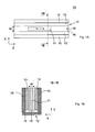
- FIG. 1A shows an electric motor 10 according to the invention, a primary part 11 for Generation of a traveling magnetic field and a secondary part 12 for the provision of a static magnetic field.
- FIG. 1B shows the electric motor 10 in one Section 1B-1B according to Fig. 1 A.
- FIG. 2A shows an electric motor 20 according to the invention, which has a primary part 21 for Generation of a traveling magnetic field and a secondary part 22 for the provision of a static magnetic field.
- FIG. 2B shows the electric motor 20 in one Section 2B-2B according to FIG. 2A.
- the electric motors 10 and 20 are both designed as a linear motor.
- the primary part 11 and the secondary part 12 or the primary part 21 and the secondary part 22 are respectively so formed such that the primary part 11 relative to the secondary part 12 and the primary part 21st relative to the secondary part 22 in the Z-direction of a coordinate system XYZ movable are, as in Fig. 1A by a double arrow on the primary part 11 and in Fig. 2A by a Double arrow on the secondary part 22 is indicated.
- the electric motors 10 and 20 differ essentially by the mass of Longitudinal extent of the primary parts 11 and 21 and the secondary parts 12 and 22 in the respective Z direction.
- the primary part 11 in comparison to the secondary part 12 a smaller extension in the Z direction.
- the electric motor 10 is therefore preferably used in applications in which the primary part 11 (im Contrary to the secondary part 12) to be moved by a relatively large distance.
- the primary part 21 in comparison to Abutment 22 a greater extension in the Z direction.
- the electric motor 20 is therefore preferably usable in applications in which the secondary part 22 (im Contrary to the primary part 21) to be moved by a relatively large distance.
- the secondary part 12 has two devices 13, 13 'in the form of a rectangular Have plate and parallel to the Z-direction so arranged at a distance from each other are that they limit an air gap 18 of the width W.
- the devices 13 and 13 ' are each attached to supports 15, which in turn are fixed to a base plate 16.
- Of the Primary part 11 is shaped and arranged such that it is in the air gap 18 in the Z-direction is movable.
- a conventional (not shown in FIGS. 1A and 1B) Guide is provided to the primary part 11 in a movement relative to Secondary part 12 in the Z direction to lead.
- the devices 13 and 13 ' comprise respectively electromagnetic means, hereinafter in connection with Figs. 3B-C be described in more detail and each to provide a static Magnetic field serve.
- This magnetic field is usually generated so that it is in the Air gap 18, but possibly also on the air gap 18 facing away from the sides the devices 13 and 13 'is present.
- the carrier 15 made of a soft magnetic material be made.
- the secondary part 22 is analogous in terms of its structure and its function Secondary part 12 is formed.
- the secondary part 22 has two devices 23, 23 ', which have the shape of a rectangular Have plate and parallel to the Z-direction so arranged at a distance from each other are that they limit an air gap 28 of width W.
- the devices 23 and 23 ' are each attached to carriers 25, which in turn are fixed to a base plate 26.
- Of the Primary part 21 is shaped and arranged such that it is in the air gap 28 in the Z-direction is movable.
- a conventional (not shown in FIGS. 2A and 2B) Guide is provided to the secondary part 22 in a movement relative to Primary 21 to guide in the Z direction.
- the devices 23 and 23 'each comprise Electromagnetic means, in the following in connection with Figs.
- the carrier 25 can be made of a soft magnetic Be made of material.
- the primary parts 11 and 22 each comprise electromagnetic means, which in the In connection with Fig. 3A will be described in more detail and the function have to create a traveling magnetic field.
- the mentioned electromagnetic Means are preferably designed to generate one in the Z direction wandering magnetic field are suitable.
- FIG. 3A shows the primary part 11 in a plan view in the X direction.
- FIG. 3B shows - also in a plan view in the X direction - the device 13 and the Device 13 ', which coincides identically with the device 13.
- the Fig. 3C shows the device 13 or 13 'in a cross section 3C-3C according to FIG. 3B along the in FIG. 3B by the points A, B, C and D marked traverse.
- the primary part 11 comprises a substrate 30, on whose base surfaces a conductor track 40 is applied.
- the conductor track 40 has two ends, which are each connected to an electrical connection 47 and 48, respectively.
- an electrical voltage U P can be applied to supply the conductor 40 with an electric current I P.
- the track has track portions 41 and 42 which are respectively disposed on different sides of the substrate 30 and connected to each other via an electrical connection 45 at their respective ends.
- the conductor track sections 41 which are located on the base surface of the substrate 30 facing the viewer, are shown by solid lines and the conductor track sections 42, which are located on the base side of the substrate 30 remote from the viewer, in each case by dashed lines Lines shown.
- the conductor track sections 41 and 42 are connected in series such that a plurality of coils each having one turn are formed on the substrate 30.
- the coils are in the Z direction - juxtaposed - juxtaposed.
- the conductor track sections 41 and 42 are connected in such a way that adjacent coils are respectively traversed by the current I P in the opposite sense of circulation.
- the regions of the primary part 11 which lie within the respective turn of one of the coils are marked with one of the symbols "I" or "II" depending on the respective direction of rotation of the current I P.
- the current I P may be either DC or AC.
- the magnetic field generated by the current I P in the vicinity of the conductor track 40 has a different (opposite) polarity in the regions distinguished by "I" and "II", respectively. If I P is a direct current, then a static magnetic field is created, which changes polarity at a transition between regions "I" and "II". If I P is an alternating current, then the respective polarity changes as a function of the time t and a traveling magnetic field arises, which migrates in the Z direction.
- the structure corresponds to that arranged in the secondary part 12 Devices 13 and 13 'substantially the structure of the primary part 11, if one disregards the respective different extensions of the devices 13, 13 'or of the primary part 11 in the Z direction.
- the arranged in the secondary part 12 devices 13, 13 'each comprise a substrate 50, on whose base surfaces a conductor 60 is applied.
- the conductor 60 has two ends, each connected to an electrical connection 67 and 68, respectively.
- the conductor track has conductor track sections 61 and 62, which are each arranged on different sides of the substrate 50 and connected to each other at their respective ends via an electrical connection 65.
- the conductor track sections 61 which are located on the base surface of the substrate 50 facing the viewer, are shown by solid lines, respectively, and the track sections 62, which are located on the base side of the substrate 50 facing away from the viewer, are respectively dashed Lines shown.
- the conductor track sections 61 and 62 are connected in series such that a plurality of coils each having one turn are formed on the substrate 50.
- the coils are in the Z direction - juxtaposed - juxtaposed.
- the conductor track sections 61 and 62 are connected in such a way that adjacent coils are respectively traversed by the current I S with opposite direction of circulation.
- Fig. 3B the areas of the device 13 or 13 ', which are within the respective turn of one of the coils, depending on the respective direction of rotation of the current I S with an arrow indicating the respective direction of circulation of the current I S , and a marked with the symbols "+" or "-”.
- the current I S is a direct current.
- the magnetic field generated in the vicinity of the conductor 60 by the current I S is a static magnetic field and has a different (opposite) polarity in the regions distinguished by "+" and "-", respectively.
- the regions "I” and “II" of the primary part 11 have the same extent in the Z direction.
- the areas "+” and “-” of the devices 13 and 13 'each have the same Extension in the Z direction.
- the secondary part 12 is insofar on the primary part eleventh matched as the areas "+” and "-" of the devices 13 and 13 'substantially have the same extension in the Z direction as the areas "I" and "II".
- a direct current is selected as current I S and an alternating current as current I P.
- the primary part 11 and the secondary part 12 are moved synchronously with the magnetic field generated by the current I P and traveling in the Z direction along the primary part 11. Whether the primary part 11 is moved in the (+ Z) direction or in the opposite (-Z) direction is determined by the instantaneous phase position of the alternating current I P as a function of the instantaneous position of the primary part 11 relative to the secondary part 12.
- a (not shown in FIGS. 1A-B and 3A-C) control is provided, depending on the current position of the primary part 11 relative to the secondary part 12 each of the current I S and the current I P controls in terms of amplitude, phase angle and frequency.
- the substrates 30 and 50 may preferably be made of an electrically insulating, a high Made of strength material, for example made of a plastic material or of a ceramic material. It is advantageous if the substrates 30 and 50 made of a non-ferromagnetic material. In this case, in the Operation disturbing forces between the primary part 11 and the secondary part 12 avoided and thus the relative movements between the primary part 11 and the Abutment 12 are controlled with increased accuracy.
- the structure of arranged in the secondary part 12 devices 13 and 13 'and the Primary part 11 can be modified in many ways within the scope of the invention.
- the Conductor tracks 40 and 60 could each be covered by an insulating layer, For example, such that the surfaces of the primary part 11 and the devices 13 or 13 'are formed by a flat insulating layer.
- the conductor tracks 40 and / or 50 could alternatively be guided such that the areas "I” or "II" and / or "+” and "-” are each surrounded by conductor track sections, each with a coil form several turns.
- the coils can also from Be conductor sections formed on only one side of the substrates 30 and 50, respectively are formed. Coils with multiple turns can be used, for example, in Layered structures of several layers, each electrically conductive and electrically Insulating areas include, be formed.
- the different layers can successively applied to the substrate 30 or 50 and optionally suitable be structured.
- the primary part according to FIG. 3A represents a simple example of a single-phase can be controlled primary part.
- the primary part 11 with several Conductors should be provided independently with an electric current can be supplied. In this case could be different in the tracks Alternating currents each having a different phase are fed to one to generate a wandering magnetic field.
- the arrangement of the various in the primary part 11 arranged conductor tracks can be geometrically adjusted with respect to the Arrangement of the designated "+" and "-" areas of the devices 13 and 13 ', to to optimize the electric motor 11.
- Concepts for such optimizations of the primary part are for example from the patent applications EP 0 949 749 A1 or WO 00/49702 A1 known.
- the secondary part 12 comprises two devices 13 and 13 ', which are constructed identically and are also arranged symmetrically with respect to the primary part 11. This arrangement has the advantage that during operation of the electric motor 10 no forces between the primary part 11 and the secondary part 12 which are perpendicular to the Z-direction (i.e. the direction in which the primary part 11 is movable relative to the secondary part 12) act.
- the secondary part 12 could also be replaced by a secondary part, the only one of the devices 13 and 13 'has.
- the Primary part 21 has a greater longitudinal extent in the Z direction than the Secondary part 22. Accordingly, the primary part 21 may have the same structure as in FIG Fig. 3A illustrated primary part 11 and the devices 23, 23 'have the same structure as the in Fig.
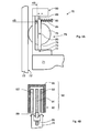
- FIGS. 4A-B and 5A-B show two different uses for one according to the Invention trained electric motor in an elevator.
- FIG. 4A shows an electric motor 90 designed according to the invention, which is in a Elevator 70 is installed.
- the elevator 70 comprises a car 71, which along a Guide surface 72 'is guided on a guide rail 72.
- Fig. 4A is only a part of the elevator 70 in the immediate vicinity of the electric motor 90.
- a drive for moving the cabin 71 along the guide surface 72 'and other common Elevator components are not shown.
- a guide device 75 is provided to guide the cabin 71 along the Guide surface 72 '.
- the guiding device 75 comprises: (i) a bracket 77 mounted on the cab 71; (ii) a Guide member 76 formed as a roller rotatable about a rotation axis 80; (iii) a lever 78 in which the axis of rotation 80 is mounted and which is mounted in the carrier 77 mounted, arranged at one end of the lever 78 axis of rotation 79 is pivotable; (Iv) a rod-shaped guide device 85 which is arranged on the carrier 77 and to Guiding the end of the lever 78 remote from the rotation axis 79; (v) a spring 86, which is arranged between the lever 78 and one end of the guide device 85 and biased such that the guide member 76 with each movement of the car 71 along the guide rails 72 with the guide surface 72 'is brought into contact and with a certain (given in certain limits) force against the respective Guide surface 72 'is pressed.
- the guide member 76 By means of a pivoting movement of the lever 78 to the Rotary axis 79, the guide member 76 can be moved relative to the car 71. in the In the present case, the guide element 76 rolls along with a movement of the car 71 along the guide rail 72 on the respective guide surface 72 'from.
- the electric motor 90 is fixed to the carrier 77 and the lever 76 such that the instantaneous position of the guide member 76 with respect to the cabin 71 by means of Electric motor 90 can be changed electronically controlled.
- FIG. 4B shows the electric motor 90 in a section 4B-4B according to FIG. 4A.
- the electric motor 90 is designed as a linear motor and is essentially like the Electric motors 10 and 20 constructed.
- the electric motor 90 includes a primary part 91 for generating a traveling magnetic field and a secondary part 92 for Provision of a static magnetic field.
- the secondary part 92 corresponds in terms of its construction essentially the secondary parts 12 and 22 of the electric motors 10th or 20.
- the secondary part 92 comprises two devices 93 and 93 ', which, like the Devices 13 and 13 'are constructed and, for example, after the in Figs. 3B-C specified scheme can be realized.
- the Devices 13 and 13 ' ach one arranged on a substrate trace, the supplied with an electric current for generating a static magnetic field is.
- the respective substrates are plate-shaped and have flat surfaces.
- the Devices 93 and 93 ' are arranged parallel to each other and on a support 95, which, as shown in FIG. 4B, has a U-shaped cross-section, fixed in such a way, an air gap is formed between the devices 93 and 93 '.
- the primary part 91 is arranged movable.
- the primary part 91 corresponds with regard to its structure essentially the primary parts 11 and 21 of the Electric motors 10 and 20. It can, for example, after that indicated in FIG. 3A Scheme be realized.
- the traveling magnetic field for example a arranged on a substrate trace, which can be supplied with an alternating current is provided.
- the primary part 91 relative to the secondary part 92 (synchronous with the migratory generated by the primary part 91 Magnetic field) are moved. This movement takes place in the present case in the Longitudinal direction of the guide device 85, as shown in Fig. 4A by a double arrow is indicated.
- the secondary part 92 is on the carrier 77 attached.
- the remote from the axis of rotation 79 end of the lever 78 by means of a connecting element 89 connected to the primary part 91. Accordingly goes during operation of the electric motor 90, a movement of the primary part 91 with a Pivoting movement of the lever 78 about the rotation axis 79 associated.
- a suitable electrical control of the electric motor 90 can thus the guide member 76 relative be moved to the cabin 71. Accordingly, the position of the cab 71 relative to the guide surface 72 'are moved, with which the guide member 76 is in contact.
- the distance between the car 71 and the guide surface 72 'in Range controlled to vary.
- a motor control (not shown) for the Electric motor 90 is provided, which in response to signals from suitable sensors Currents for supplying the primary part 91 and the secondary part 92 and the Devices 93 and 93 ', for example, in terms of their amplitude, their frequency and the layer controls its phase to control the position of the guide member 76 relative to Cabin 71 to influence according to predetermined criteria.
- you can Sensors are provided, which during a drive of the cabin 71 along the Guide surface 72 'oscillations of the car 71, transverse to the direction of movement of Cabin 71 occur, detect.
- These vibrations can be reduced or optionally be suppressed by the motor control the electric motor 90 in Depending on signals from these sensors to movements that led to a Compensation of the vibrations of the cabin 71 lead.
- the elevator 70 according to FIGS. 4A and 4B may, in the context of the invention, be different Modes are modified.
- the electric motor 90 can be so with respect to the guide device 75th be arranged that the primary part 91 stationary with respect to the cabin 71 and the Secondary part 92 together with the guide member 75 relative to the cab 71 movable is. Furthermore, one of the devices 93 or 93 'can be dispensed with. Moreover, the primary part 91 may have a plurality of tracks independently of each other Power can be supplied to the migratory magnetic field with multiple currents produce. These streams can have several different phases.
- the power supply for the primary part must be designed to be multiphase and the Motor control for the electric motor 90 must be suitably adapted to the by the respective conductor tracks of the primary part 91 flowing currents in terms of their Amplitude, their frequency and their phase suitable to control.
- the Carrier 95 for the devices 93 and 93 'made of a soft magnetic material be made to a magnetic flux on the primary part 91 facing away Pages of the devices 93 and 93 'in the carrier 95 to concentrate.
- a plurality of guide devices 75 may be attached to the cabin 71, for example, two in the Longitudinal direction of the respective guide rail 72 spaced guide devices 75.
- the guide rails 72 may also be in addition to those already described Guide surface 72 'further guide surfaces for guiding the car 71 in the Longitudinal direction of the respective guide rail 72 are suitable.
- each Guide rail 72 could, for example, two or three in the longitudinal direction of Guide rail 72 have extending guide surfaces, each adjacent Guide surfaces - based on a cross section of the respective guide rail 72 - in an angle of less than 180 ° (for example, 90 °) are arranged to each other. Accordingly, a plurality of guide devices 75 on the cabin 71 may be so be arranged that the car 71 - as in connection with FIG.
- Vibration degrees of freedom of the cabin 71 can be measured by sensors.
- an engine control can be provided, the the electric motors 90 suitably controls and causes to move to a Compensate for the vibrations.
- the number and arrangement of Guiding devices 75 and the electric motors 90 may correspond to the number of Vibration degrees of freedom to be detected by the engine control to get voted.
- FIG. 5A shows an elevator 100, which is a cabin 102 movable along a path includes.
- FIG. 5B illustrates the elevator 100 in a section 5B-5B according to FIG. 5A.
- a guide rail 103 is disposed on a wall 101 of a hoistway.
- the Cabin is in a movement along the track on the guide rail 103 with conventional guide means, however, which are not shown in Fig. 5A-B, out.
- a trained according to the invention electric motor 110 serves as a drive for movement the car 102 along the guide rail 103.
- the electric motor 110 is a linear motor designed on the basis of in connection with the electric motors 10 and 20 mentioned concepts.
- the electric motor 110 includes a primary part 111 for generation a traveling magnetic field and a secondary part 112 for providing a static magnetic field.
- the primary part 111 and the secondary part 112 are arranged such that the primary part 111 and the secondary part 112 under an effect of the migrating magnetic field relative are movable relative to each other.
- the primary part 111 is arranged such that by means of of the primary part 111 can be generated traveling magnetic field parallel to the path of the cabin emigrated.
- the primary part 111 extends along the entire length of the path of the car 102. It is attached to the guide rail 103.
- the primary part 111 is composed of a plurality of longitudinally along the path of the cabin successively arranged modules, respectively a conductor track arranged on a substrate, wherein the tracks of the various modules for generating the traveling magnetic field with a current are available.
- Each module may, for example, like the primary part 11 of the Electric motor 10 to be constructed.
- the tracks of the various modules can be used in Be connected in series and have a common power supply.
- the tracks The different modules can also have a separate power supply. The latter offers the possibility of the migrating magnetic field - as needed - only in individual sections of the path of the car 102 to produce.
- the secondary part 112 has a shorter extension in the direction of the path of the car 102 as the primary part 111 and is fixed to the cab 102. In the present case is a Connecting element 109 between the secondary part 112 and the car 102nd arranged to the secondary part 112 at a suitable distance from the car 102 to hold.
- the secondary part 112 has - as a comparison with the Fig. 1 B, 2B and 4B indicates - Essentially the same structure as the secondary parts of the electric motors 10, 20 and 90th
- the secondary part 112 comprises two devices 113 and 113 ', which, like the Devices 13 and 13 'are constructed and, for example, after the in Figs. 3B-C specified scheme can be realized. Accordingly, the Devices 113 and 113 'each one arranged on a substrate trace, the supplied with an electric current for generating a static magnetic field is.
- the respective substrates are plate-shaped and have flat surfaces.
- the carrier 115 may also be made of a soft magnetic material Be made of material.
- the secondary part 112 is arranged such that the primary part 111 into the air gap between the devices 113 and 113 'of the secondary part 112 protrudes and not with the Devices 113 and 113 'is brought into contact when the car 102 along the Guide rail 103 is moved.
- the latter assumes that the mentioned Guide means for guiding the cab 103 along the guide rail 103 the to ensure the required degree of precision and rigidity.
- the cab 102 may be moved or held at a predetermined location be suitable by the conductor tracks of the primary part 111 and the secondary part 112 be powered.
- the primary part 111 is driven to enter migratory magnetic field generated, then the car 102 is synchronized with the moving magnetic field along the guide rail 103 moves.
- both the Primary part 111 and the primary part 112 are supplied with a direct current, then For example, the cab 102 may be held at a predetermined location.
- the engine 110 may be designed so that the force that the electric motor 110 in operation on the cabin 102 exercises, sufficient to hold the cabin without further aids.
- the elevator 100 may have no support means for the car 102 (i.e., without ropes or belts). and operated without counterweight.
- the elevator 100 can be modified in many ways within the scope of the invention.
- the Power supply for the tracks of the primary part 111 and the secondary part 112 also be designed such that currents only in the areas of the primary part 111 and the secondary part 112 flow, in which the primary part 111 with the secondary part 112th overlaps. In this way, the power consumption of the electric motor 110 can be reduced become.
- the elevator 100 can be attached to a plurality of guide rails 103 be guided.
- the guide rails may be on different sides of the cab 102 be arranged.
- the cabin 102 may include a plurality of electric motors 110 are driven.
- the primary parts 111 of the various Electric motors 110 disposed on the respective guide rails and the corresponding secondaries 111 are attached to the cab 102, for example according to the concept shown in Figs. 5A and 5B.
- the electric motor 110 can each be replaced by another inventively designed electric motor, the primary part stationary with respect to the cabin 103 and its secondary part stationary with respect to the path of the cab 103 is arranged.
- the extension of the respective primary part along the path can be short compared to the extension be of the corresponding secondary part.
- the mentioned electric motors and the cabin with separate means be guided along the path of the cabin 102.
- the modifications that are for the electric motors 10, 20 and 90 are disclosed analogously to the electric motor 110 transferable.
Landscapes
- Engineering & Computer Science (AREA)
- Physics & Mathematics (AREA)
- Chemical & Material Sciences (AREA)
- Combustion & Propulsion (AREA)
- Electromagnetism (AREA)
- Power Engineering (AREA)
- Linear Motors (AREA)
Abstract
Description
- Fig. 1A:
- Eine Ansicht eines erfindungsgemässen Elektromotors, mit einem Primärteil und einem Sekundärteil, wobei der Primärteil relativ zum Sekundärteil bewegbar ist;
- Fig. 1 B:
- den Elektromotor gemäss Fig. 1 A in einem Schnitt 1B-1B;
- Fig. 2A:
- eine Ansicht eines anderen erfindungsgemässen Elektromotors, mit einem Primärteil und einem Sekundärteil, wobei der Sekundärteil relativ zum Primärteil bewegbar ist;
- Fig. 2B:
- den Elektromotor gemäss Fig. 2A in einem Schnitt 2B-2B;
- Fig. 3A:
- den Primärteil gemäss Fig. 1A in einer detaillierteren Darstellung;
- Fig. 3B:
- den Sekundärteil gemäss Fig. 1A in einer detaillierteren Darstellung;
- Fig. 3C:
- den Sekundärteil gemäss Fig. 3B in einem Schnitt 3C-3C;
- Fig. 4A:
- einen Aufzug mit einer Kabine und einem Führungselement zur Führung der Kabine und mit einem erfindungsgemässen Elektromotor zur Bewegung des Führungselements relativ zur Kabine;
- Fig. 4B:
- den Elektromotor gemäss Fig. 4A in einem Schnitt 4B-4B;
- Fig. 5A:
- einen Aufzug mit einer Kabine und einem erfindungsgemässen Elektromotor als Antrieb zur Bewegung der Kabine;
- Fig. 5B:
- den Aufzug gemäss Fig. 5A in einem Schnitt 5B-5B.
Claims (10)
- Elektromotor (10, 20, 90, 110), mit einem Primärteil (11, 21, 91, 111) zur Erzeugung eines wandernden Magnetfeldes und einem Sekundärteil (12, 22, 92, 112) zur Bereitstellung eines statischen Magnetfeldes, wobei der Sekundärteil und der Primärteil unter einer Wirkung des wandernden Magnetfeldes relativ zueinander bewegbar sind, dadurch gekennzeichnet, dass der Sekundärteil (12, 22, 92, 112) ein Substrat (50) und eine auf das Substrat (50) aufgebrachte Leiterbahn (60) in Form einer Schichtstruktur (13, 13', 23, 23', 93, 93', 113, 113') umfasst und dass die Leiterbahn (60) zwecks Erzeugung des statischen Magnetfeldes mit einem elektrischen Strom (IS) versorgbar ist.
- Elektromotor nach Anspruch 1, dadurch gekennzeichnet, dass das Substrat (50) eine flache Oberfläche aufweist.
- Elektromotor nach einem der Ansprüche 1-2, dadurch gekennzeichnet, dass mindestens ein Abschnitt der Leiterbahn (60) die Form einer Spule aufweist, wobei jede Spule eine oder mehrere Windungen umfasst.
- Elektromotor nach einem der Ansprüche 1-3, dadurch gekennzeichnet, dass die Leiterbahn (60) aus Leiterbahnabschnitten (61, 62) zusammengesetzt ist, die jeweils in verschiedenen Schichten der Schichtstruktur (13, 13', 23, 23', 93, 93', 113, 113') ausgebildet sind, , wobei vorzugsweise ein erster Teil (61) der Leiterbahn (60) an einer ersten Oberfläche des Substrats (50) und ein zweiter Teil (62) der Leiterbahn (60) an einer zweiten Oberfläche des Substrats (50) ausgebildet ist, wobei eine elektrische Verbindung (65) zwischen dem ersten und dem zweiten Teil hergestellt ist.
- Elektromotor nach einem der Ansprüche 1-4, dadurch gekennzeichnet, dass der Primärteil (11) eine auf einem Substrat (30) angeordnete Leiterbahn (40) oder mehrere auf dem Substrat (30) angeordnete Leiterbahnen umfasst und dass die jeweilige Leiterbahn (40) zwecks Erzeugung des wandernden Magnetfeldes mit einem elektrischen Strom (IP(t)), dessen Stromstärke mit der Zeit (t) variiert, versorgbar ist.
- Elektromotor nach einem der Ansprüche 1-5, dadurch gekennzeichnet, dass die Schichtstruktur (13, 13', 23, 23', 93, 93', 113, 113') des Sekundärteils (12, 22, 92, 112) an einem Träger (15, 25, 95, 115) aus einem magnetischen Material befestigt ist, wobei der Träger (15, 25, 95, 115) auf einer dem Primärteil (11, 21, 91, 111) abgewandten Seite der Schichtstruktur (13, 13', 23, 23', 93, 93', 113, 113') angeordnet ist.
- Aufzug (100) mit einem Elektromotor (110) nach einem der Ansprüche 1-6, wobei der Aufzug (100) eine Kabine (102) umfasst und die Kabine (102) mittels des Elektromotors (110) längs einer Bahn bewegbar ist und wobei der Primärteil (111) ortsfest längs der Bahn und der Sekundärteil (112) an der Kabine (102) angeordnet ist oder der Sekundärteil ortsfest längs der Bahn und der Primärteil an der Kabine angeordnet ist.
- Aufzug (70) mit einem Elektromotor (90) nach einem der Ansprüche 1-6, wobei der Aufzug (70) eine längs mindestens einer Führungsfläche (72') bewegbare Kabine (71) und ein Führungselement (76), welches an der Kabine (71) bewegbar angeordnet und mit der Führungsfläche (72') in Kontakt gebracht ist, umfasst und das Führungselement (76) mit dem Elektromotor (90) relativ zur Kabine (71) bewegbar ist.
- Aufzug nach Anspruch 8, wobei der Primärteil (91) zusammen mit dem Führungselement (76) bewegbar und der Sekundärteil (92) ortsfest bezüglich der Kabine (71) angeordnet ist oder dass der Sekundärteil zusammen mit dem Führungselement bewegbar und der Primärteil ortsfest bezüglich der Kabine angeordnet ist.
- Aufzug nach einem der Ansprüche 8 oder 9, mit einer Steuerung für den Elektromotor (90) zur Reduktion von Schwingungen der Kabine (71) während einer Bewegung der Kabine längs der Führungsfläche (72').
Priority Applications (1)
| Application Number | Priority Date | Filing Date | Title |
|---|---|---|---|
| EP04018643A EP1507329A1 (de) | 2003-08-14 | 2004-08-06 | Elektromotor, Aufzug mit einer mit einem Elektromotor bewegbaren Kabine und Aufzug mit einer Kabine und mit einem Elektromotor zur Bewegung eines Führungselements relativ zu der Kabine |
Applications Claiming Priority (3)
| Application Number | Priority Date | Filing Date | Title |
|---|---|---|---|
| EP03405593 | 2003-08-14 | ||
| EP03405593 | 2003-08-14 | ||
| EP04018643A EP1507329A1 (de) | 2003-08-14 | 2004-08-06 | Elektromotor, Aufzug mit einer mit einem Elektromotor bewegbaren Kabine und Aufzug mit einer Kabine und mit einem Elektromotor zur Bewegung eines Führungselements relativ zu der Kabine |
Publications (1)
| Publication Number | Publication Date |
|---|---|
| EP1507329A1 true EP1507329A1 (de) | 2005-02-16 |
Family
ID=33566334
Family Applications (1)
| Application Number | Title | Priority Date | Filing Date |
|---|---|---|---|
| EP04018643A Withdrawn EP1507329A1 (de) | 2003-08-14 | 2004-08-06 | Elektromotor, Aufzug mit einer mit einem Elektromotor bewegbaren Kabine und Aufzug mit einer Kabine und mit einem Elektromotor zur Bewegung eines Führungselements relativ zu der Kabine |
Country Status (1)
| Country | Link |
|---|---|
| EP (1) | EP1507329A1 (de) |
Cited By (6)
| Publication number | Priority date | Publication date | Assignee | Title |
|---|---|---|---|---|
| DE102006023493B4 (de) * | 2006-05-18 | 2008-07-10 | Intrasys Gmbh Innovative Transport-Systeme | Mehrphasiges Wicklungsteil für einen Linearmotor oder Lineargenerator |
| WO2012045606A1 (de) | 2010-10-07 | 2012-04-12 | Thyssenkrupp Transrapid Gmbh | Aufzuganlage |
| DE102014219862A1 (de) * | 2014-09-30 | 2016-03-31 | Thyssenkrupp Ag | Aufzugsystem |
| DE102015221653A1 (de) | 2015-11-04 | 2017-05-04 | Thyssenkrupp Ag | Fangrahmen für eine Aufzugsanlage |
| DE102016205463A1 (de) | 2016-04-01 | 2017-10-05 | Thyssenkrupp Ag | Führungsanordnung für eine Aufzuganlage |
| DE102017118507A1 (de) * | 2017-08-14 | 2019-02-14 | Thyssenkrupp Ag | Aufzugsanlage und Verfahren zum Betreiben einer Aufzugsanlage |
Citations (13)
| Publication number | Priority date | Publication date | Assignee | Title |
|---|---|---|---|---|
| US3872357A (en) * | 1972-05-08 | 1975-03-18 | Hitachi Ltd | Linear synchronous motor for high-speed vehicles |
| JPH03249019A (ja) * | 1990-02-27 | 1991-11-07 | Mitsubishi Heavy Ind Ltd | 垂直搬送装置 |
| DE4115728A1 (de) * | 1990-05-14 | 1991-11-21 | Mitsubishi Electric Corp | Aufzug mit linearmotor-antrieb |
| DE4139471A1 (de) * | 1990-11-30 | 1992-06-11 | Mitsubishi Electric Corp | Antriebssystem fuer ein magnetschwebefahrzeug |
| JPH04281359A (ja) * | 1991-03-05 | 1992-10-06 | Fuji Electric Co Ltd | リニア同期機 |
| JPH06263365A (ja) * | 1991-05-24 | 1994-09-20 | Fujitec Co Ltd | エレベータ装置 |
| US5896949A (en) * | 1995-03-10 | 1999-04-27 | Inventio Ag | Apparatus and method for the damping of oscillations in an elevator car |
| JP2000228858A (ja) * | 1999-02-08 | 2000-08-15 | Matsushita Electric Works Ltd | リニアモータのコイル構造 |
| US6452292B1 (en) * | 2000-06-26 | 2002-09-17 | Nikon Corporation | Planar motor with linear coil arrays |
| US20030000778A1 (en) * | 2001-06-14 | 2003-01-02 | Rory Smith | Drive system for multiple elevator cars in a single shaft |
| US20030080631A1 (en) * | 2001-11-01 | 2003-05-01 | Nikon Corporation | Sheet coils and linear motors comprising same, and stage units and microlithography apparatus comprising said linear motors |
| EP1311056A1 (de) * | 2000-06-19 | 2003-05-14 | Kabushiki Kaisha Yaskawa Denki | Linearmotor |
| EP1320180A1 (de) * | 2001-12-14 | 2003-06-18 | Gisulfo Baccini | Linearmotor und Herstellungsverfahren dafür |
-
2004
- 2004-08-06 EP EP04018643A patent/EP1507329A1/de not_active Withdrawn
Patent Citations (13)
| Publication number | Priority date | Publication date | Assignee | Title |
|---|---|---|---|---|
| US3872357A (en) * | 1972-05-08 | 1975-03-18 | Hitachi Ltd | Linear synchronous motor for high-speed vehicles |
| JPH03249019A (ja) * | 1990-02-27 | 1991-11-07 | Mitsubishi Heavy Ind Ltd | 垂直搬送装置 |
| DE4115728A1 (de) * | 1990-05-14 | 1991-11-21 | Mitsubishi Electric Corp | Aufzug mit linearmotor-antrieb |
| DE4139471A1 (de) * | 1990-11-30 | 1992-06-11 | Mitsubishi Electric Corp | Antriebssystem fuer ein magnetschwebefahrzeug |
| JPH04281359A (ja) * | 1991-03-05 | 1992-10-06 | Fuji Electric Co Ltd | リニア同期機 |
| JPH06263365A (ja) * | 1991-05-24 | 1994-09-20 | Fujitec Co Ltd | エレベータ装置 |
| US5896949A (en) * | 1995-03-10 | 1999-04-27 | Inventio Ag | Apparatus and method for the damping of oscillations in an elevator car |
| JP2000228858A (ja) * | 1999-02-08 | 2000-08-15 | Matsushita Electric Works Ltd | リニアモータのコイル構造 |
| EP1311056A1 (de) * | 2000-06-19 | 2003-05-14 | Kabushiki Kaisha Yaskawa Denki | Linearmotor |
| US6452292B1 (en) * | 2000-06-26 | 2002-09-17 | Nikon Corporation | Planar motor with linear coil arrays |
| US20030000778A1 (en) * | 2001-06-14 | 2003-01-02 | Rory Smith | Drive system for multiple elevator cars in a single shaft |
| US20030080631A1 (en) * | 2001-11-01 | 2003-05-01 | Nikon Corporation | Sheet coils and linear motors comprising same, and stage units and microlithography apparatus comprising said linear motors |
| EP1320180A1 (de) * | 2001-12-14 | 2003-06-18 | Gisulfo Baccini | Linearmotor und Herstellungsverfahren dafür |
Non-Patent Citations (2)
| Title |
|---|
| OWEN E L: "SYNCHRONOUS MOTORS FOR A-C ADJUSTABLE-SPEED DRIVES", RECORD OF THE ANNUAL PULP AND PAPER INDUSTRY TECHNICAL CONFERENCE. HYANNIS, JUNE 21 - 25, 1993, NEW YORK, IEEE, US, 21 June 1995 (1995-06-21), pages 54 - 61, XP000416164 * |
| PATENT ABSTRACTS OF JAPAN vol. 018, no. 669 (M - 1725) 16 December 1994 (1994-12-16) * |
Cited By (9)
| Publication number | Priority date | Publication date | Assignee | Title |
|---|---|---|---|---|
| DE102006023493B4 (de) * | 2006-05-18 | 2008-07-10 | Intrasys Gmbh Innovative Transport-Systeme | Mehrphasiges Wicklungsteil für einen Linearmotor oder Lineargenerator |
| WO2012045606A1 (de) | 2010-10-07 | 2012-04-12 | Thyssenkrupp Transrapid Gmbh | Aufzuganlage |
| US9487377B2 (en) | 2010-10-07 | 2016-11-08 | Thyssenkrupp Transrapid Gmbh | Elevator installation |
| DE102014219862A1 (de) * | 2014-09-30 | 2016-03-31 | Thyssenkrupp Ag | Aufzugsystem |
| DE102015221653A1 (de) | 2015-11-04 | 2017-05-04 | Thyssenkrupp Ag | Fangrahmen für eine Aufzugsanlage |
| US11046555B2 (en) | 2015-11-04 | 2021-06-29 | Tk Elevator Innovation And Operations Gmbh | Frame for an elevator system |
| DE102016205463A1 (de) | 2016-04-01 | 2017-10-05 | Thyssenkrupp Ag | Führungsanordnung für eine Aufzuganlage |
| WO2017167881A1 (de) | 2016-04-01 | 2017-10-05 | Thyssenkrupp Elevator Ag | Führungsanordnung für eine aufzuganlage |
| DE102017118507A1 (de) * | 2017-08-14 | 2019-02-14 | Thyssenkrupp Ag | Aufzugsanlage und Verfahren zum Betreiben einer Aufzugsanlage |
Similar Documents
| Publication | Publication Date | Title |
|---|---|---|
| DE3705089C2 (de) | ||
| DE69503336T2 (de) | Linearantrieb | |
| EP2099640B1 (de) | Magnetschwebefahrzeug mit wenigstens einem magnetsystem | |
| DE2946147A1 (de) | Elektrodynamischer linearmotor | |
| AT520088A4 (de) | Verfahren zum Betreiben einer Transporteinrichtung in Form eines Langstatorlinearmotors | |
| EP2884639A1 (de) | Lineares Transportsystem | |
| DE102005041887A1 (de) | Linearmotor und Vorrichtung mit sich linear bewegendem Gestell | |
| AT523217A1 (de) | Transporteinrichtung | |
| DE102009059323A1 (de) | Linearmotor | |
| EP3487049B1 (de) | Linearmotor mit transversalfluss | |
| EP1507329A1 (de) | Elektromotor, Aufzug mit einer mit einem Elektromotor bewegbaren Kabine und Aufzug mit einer Kabine und mit einem Elektromotor zur Bewegung eines Führungselements relativ zu der Kabine | |
| DE102004057275A1 (de) | Lineargleitvorrichtung | |
| WO2001096139A2 (de) | Verfahren und anordnung zum berührungslosen transport eines fahrzeuges auf einer schienenanordnung | |
| DE102005002038B4 (de) | Schiebetür mit einem magnetischen Antriebssystem mit einem Linearmotor-Stator | |
| EP2649713B1 (de) | Linearmotor, insbesondere linearmotor mit einem pendelfeld | |
| DE102009025342B4 (de) | Permanentmagneterregte Anordnung mit stellbaren Zusatzmagneten bei Energiewandlern | |
| DE19849728A1 (de) | Antriebsvorrichtung für Arbeitselemente von Textilmaschinen | |
| EP1444766B1 (de) | Linearantrieb mit bewegter, massereduzierter passiveinheit | |
| EP1647655B1 (de) | Schiebetür mit einem Antriebssystem mit einer Magnetreihe | |
| EP0300123B1 (de) | Elektrischer Antrieb oder Generator | |
| EP0298194A2 (de) | Elektrischer Antrieb | |
| EP2005566A1 (de) | Linearantrieb mit bewegter, massereduzierter und seitengeführter passiveinheit | |
| DE20316493U1 (de) | Elektrischer Linearantrieb | |
| DE102021110415A1 (de) | Magnetische Lagereinrichtung | |
| EP0300125A1 (de) | Elektrischer Antrieb oder Generator |
Legal Events
| Date | Code | Title | Description |
|---|---|---|---|
| PUAI | Public reference made under article 153(3) epc to a published international application that has entered the european phase |
Free format text: ORIGINAL CODE: 0009012 |
|
| AK | Designated contracting states |
Kind code of ref document: A1 Designated state(s): AT BE BG CH CY CZ DE DK EE ES FI FR GB GR HU IE IT LI LU MC NL PL PT RO SE SI SK TR |
|
| AX | Request for extension of the european patent |
Extension state: AL HR LT LV MK |
|
| 17P | Request for examination filed |
Effective date: 20050804 |
|
| AKX | Designation fees paid |
Designated state(s): AT BE BG CH CY CZ DE DK EE ES FI FR GB GR HU IE IT LI LU MC NL PL PT RO SE SI SK TR |
|
| REG | Reference to a national code |
Ref country code: HK Ref legal event code: DE Ref document number: 1074917 Country of ref document: HK |
|
| 17Q | First examination report despatched |
Effective date: 20060308 |
|
| STAA | Information on the status of an ep patent application or granted ep patent |
Free format text: STATUS: THE APPLICATION IS DEEMED TO BE WITHDRAWN |
|
| 18D | Application deemed to be withdrawn |
Effective date: 20070301 |
|
| REG | Reference to a national code |
Ref country code: HK Ref legal event code: WD Ref document number: 1074917 Country of ref document: HK |