EP1507329A1 - Electric motor, lift with a car moved with an electric motor and lift with a car and an electric motor for actuating a guide member relatively to the car - Google Patents
Electric motor, lift with a car moved with an electric motor and lift with a car and an electric motor for actuating a guide member relatively to the car Download PDFInfo
- Publication number
- EP1507329A1 EP1507329A1 EP04018643A EP04018643A EP1507329A1 EP 1507329 A1 EP1507329 A1 EP 1507329A1 EP 04018643 A EP04018643 A EP 04018643A EP 04018643 A EP04018643 A EP 04018643A EP 1507329 A1 EP1507329 A1 EP 1507329A1
- Authority
- EP
- European Patent Office
- Prior art keywords
- electric motor
- primary part
- secondary part
- cabin
- magnetic field
- Prior art date
- Legal status (The legal status is an assumption and is not a legal conclusion. Google has not performed a legal analysis and makes no representation as to the accuracy of the status listed.)
- Withdrawn
Links
Images


Classifications
-
- H—ELECTRICITY
- H02—GENERATION; CONVERSION OR DISTRIBUTION OF ELECTRIC POWER
- H02K—DYNAMO-ELECTRIC MACHINES
- H02K41/00—Propulsion systems in which a rigid body is moved along a path due to dynamo-electric interaction between the body and a magnetic field travelling along the path
- H02K41/02—Linear motors; Sectional motors
- H02K41/03—Synchronous motors; Motors moving step by step; Reluctance motors
- H02K41/031—Synchronous motors; Motors moving step by step; Reluctance motors of the permanent magnet type
-
- H—ELECTRICITY
- H02—GENERATION; CONVERSION OR DISTRIBUTION OF ELECTRIC POWER
- H02K—DYNAMO-ELECTRIC MACHINES
- H02K3/00—Details of windings
- H02K3/46—Fastening of windings on the stator or rotor structure
- H02K3/47—Air-gap windings, i.e. iron-free windings
Definitions
- the invention relates to an electric motor according to the preamble of Claim 1 and an elevator with a means of such an electric motor along a railway movable cabin.
- Another object of the invention is an elevator with a along at least one guide surface movable cabin, with a guide element, which is arranged movably on the cabin and in contact with the guide surface is brought, and with an electric motor for moving the guide member relative to the cabin.
- Electric motors of the type mentioned above are from the European Patent applications EP 0 949 748 A1 and EP 0 949 749 A1.
- linear motors each having a primary part for Generation of a traveling magnetic field and a secondary part for the provision a static magnetic field, wherein the secondary part and the primary part spatially separated by an air gap and under an effect of the wandering Magnetic field are relatively movable.
- the primary part comprises several flat, ironless coils, which are printed as Circuits are applied to an insulating substrate.
- To provide the static magnetic field are in the secondary part a plurality of permanent magnets such are arranged, that on a surface of the secondary part a periodic magnetic structure is formed.
- European Patent Application EP 0 785 162 A1 discloses an elevator with a Drive system for a cabin based on a synchronous motor Linear motor disclosed.
- the linear motor has a primary part for generating a wandering magnetic field and a secondary to provide a static Magnetic field on.
- the secondary part consists of a large number of permanent magnets, which are arranged on a wall of an elevator shaft along the path of the cabin.
- the primary part consists of coils which are arranged on one side of the cabin.
- the electric motor should - suitably dimensioned - in one Elevator as a drive for moving a cabin or for moving a Guide member be used relative to a cabin.
- the electric motor according to the invention has a primary part for generating a migratory magnetic field and a secondary to provide a static Magnetic field, wherein the secondary part and the primary part under an effect of migratory magnetic field are relatively movable.
- the secondary part comprises a conductor track arranged on a substrate, which is used to generate the static Magnetic field can be supplied with an electric current.
- the special design of the abutment allows the provision of a static magnetic field without using permanent magnets. That to the operation
- the static magnetic field required by the electric motor is generated electromagnetically by an electrical current is sent through the track. All the disadvantages that the Use of permanent magnets entails are thus avoided.
- the secondary part comprises as an essential basic element Substrate, which serves as a carrier of the conductor and for the desired mechanical Stability of the abutment ensures.
- the substrate and the conductor can be used as a Layer structure be formed.
- the track can be made of a thin, electrically conductive layer are formed, which are applied to the substrate and optionally structured appropriately.
- the substrate may be made of a high strength material. This makes possible the use of thin substrates with a large surface area. Thus, a Abutment are created, which is extremely narrow in one dimension and thus through a particularly narrow air gap between two poles of a pole pair of a Primary part can be moved. Because the trace is made of a thin conductive layer can be formed, it is possible to create a secondary part in the field of Track has a relatively smooth surface. This will make it possible to get one To provide electric motor, in which the secondary part in a particularly small distance can be arranged to the primary part and therefore operated with high efficiency is.
- the electric motor can be realized in a variety of geometries.
- the shape of the Substrate can - depending on the shape of the primary part - selected accordingly become.
- the electric motor may be constructed, for example, as a rotating motor.
- Of the Electric motor can also be designed for other types of movement, for example as a linear motor.
- the substrate may, for example, have the shape of a cylinder.
- the conductor can for example be arranged on the jacket of the cylinder be to form a rotatable about the longitudinal axis of the cylinder secondary part.
- the secondary part can also be designed as a flat disk rotatable about an axis be educated.
- the base areas of the disc stand for the arrangement the conductor track available.
- the abutment may also be considered flat, along a path of finite length be formed movable plate, wherein the base surfaces of the plate for the arrangement the track are available.
- the secondary part of an embodiment of the electric motor according to the invention can be described as a layered structure made by applying various layers to the Substrate, be conceived.
- the layers can be applied one after the other and if appropriate, be structured appropriately. That way, on the substrate three-dimensional structures of materials with different properties be applied.
- Individual layers can be made of an electrically insulating material Material consist or areas of an electrically insulating material.
- the trace may consist of trace segments, each in different layers the layer structure are formed, be composed.
- Individual sections of the For example, interconnects can cross over in different planes and in the Be separated region of the crossover by an electrically insulating layer.
- there is the possibility of individual sections of the track in different to arrange separate layers by an intermediate layer and in the intermediate layer to provide an electrically conductive region having an electrical connection between produces these sections of the track.
- Layers of the type mentioned can also be applied on both sides of the substrate and possibly structured.
- each coil one or more Includes turns.
- the coil may be disposed on one side of the substrate but can also be composed of different sections of the track, which are arranged on different sides of the substrate and electrically with each other are connected.
- each section of the conductor track has the form of a coil, the coils being such are formed such that at a current flow through the conductor track adjacent coils each generate magnetic fields with different polarity.
- the Conductor be arranged such that in a supply of the conductor with a DC generated at a surface of the secondary part of a static magnetic field whose polarity is a periodic reversal of the polarity along the direction in which the secondary part is movable relative to the primary part has. This way you can Abutment be designed to provide a large number of magnetic poles. With a suitable arrangement of the conductor can be made available on the substrate standing area can be used efficiently. This is relevant to the optimization of Efficiency of the electric motor and the accuracy with which the movement of the secondary part relative to the primary part during operation of the engine can be controlled.
- the secondary part can be used to generate the static Magnetic field also provided several tracks, which are independent from each other with an electric current can be supplied.
- the secondary part can be a static magnetic field with a particularly large Energy density can be generated.
- the maximum Force with which the secondary part during operation of the engine relative to the primary part is moved, additionally increased.
- a further development of the electric motor according to the invention has a primary part on, which comprises a substrate arranged on a conductor track, said conductor track for generating the traveling magnetic field with an electric current whose Current varies with time, can be supplied.
- the primary part can be realized according to the same technological concept on which according to the invention, the design of the secondary part is based.
- an electrical structure which serves as a layer structure can be realized, for example, by applying thin layers on a substrate and optionally by structuring these layers.
- Example meadow a plurality of serially arranged sections of the conductor track each in the form of a coil have, wherein the coils are formed such that at a current flow through the Conductor adjacent coils each magnetic fields with different polarity produce.
- both the primary part and the secondary part can be realized as Layer structures, the thin applied to a substrate electrically conductive areas include. Accordingly, both the primary part and the secondary part are with techniques manufacturable, which are used for the manufacture of printed circuits.
- This variant of the electric motor according to the invention has several advantages.
- the Primary part and the secondary part can each thin substrates, which also has a low Have weight used.
- Unlike conventional Motor designs are used in the present case for the production of magnetic Wanderfeldes or the generation of the static magnetic field neither a ferromagnetic core nor wound coils nor permanent magnets needed.
- These Variant of the electric motor can therefore be particularly lightweight, compact and cost-effective be built.
- the primary part and the Secondary part without ferromagnetic cores and without permanent magnets realize too can also simplify the control of the movement of the abutment during the Operation of the electric motor, as the disturbance forces, in conventional electric motors between a (usually with teeth and grooves provided) ferromagnetic Core and the secondary part occur, omitted. Because of the low weight is the Motor particularly suitable for controlling fast movements. Because at one Control of the engine only small masses need to be accelerated fast movements are controlled efficiently and precisely.
- the primary part several on a substrate arranged conductor tracks and that each of these tracks for the purpose of generating of the migrating magnetic field, each with an electric current whose current strength varies with time, is supplyable. Since each of the tracks independently with a Power source can be controlled, according to this concept, a multi-phase controllable electric motor are designed.
- the electric motor according to the invention can also be used in an elevator as a drive for a along a path movable cabin can be used.
- the electric motor can in the Elevator, for example, be installed such that the primary part stationary along the track and the secondary part is arranged on the cabin.
- the secondary part fixedly arranged along the track and the primary part to the cabin.
- the elevator equipped with means for guiding the cabin along the track and the Primary part and the secondary part to be arranged on these means that the Primary part and the secondary part are guided at a distance to each other when the Cabin is moved along the path.
- the latter has the advantage that every movement of the Electric motor and every movement of the cabin through a common leadership is controlled. A separate guide for the primary part or the secondary part of Electric motor can be saved in this way.
- an elevator which is a cabin movable along at least one guide surface and a guide member which is movably arranged on the cab and with the Guide surface is brought into contact
- Electric motor also as a drive for moving the guide member relative to the cabin be used.
- the electric motor can be installed in such a way that the primary part movable together with the guide element and the secondary part stationary relative the cab is arranged or that the secondary part together with the Guide element movable and arranged the primary part stationary with respect to the cabin is.
- a control for the electric motor for the reduction of vibrations the cabin, which can occur during a movement of the cabin, in the elevator be integrated.
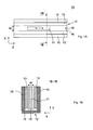
- FIG. 1A shows an electric motor 10 according to the invention, a primary part 11 for Generation of a traveling magnetic field and a secondary part 12 for the provision of a static magnetic field.
- FIG. 1B shows the electric motor 10 in one Section 1B-1B according to Fig. 1 A.
- FIG. 2A shows an electric motor 20 according to the invention, which has a primary part 21 for Generation of a traveling magnetic field and a secondary part 22 for the provision of a static magnetic field.
- FIG. 2B shows the electric motor 20 in one Section 2B-2B according to FIG. 2A.
- the electric motors 10 and 20 are both designed as a linear motor.
- the primary part 11 and the secondary part 12 or the primary part 21 and the secondary part 22 are respectively so formed such that the primary part 11 relative to the secondary part 12 and the primary part 21st relative to the secondary part 22 in the Z-direction of a coordinate system XYZ movable are, as in Fig. 1A by a double arrow on the primary part 11 and in Fig. 2A by a Double arrow on the secondary part 22 is indicated.
- the electric motors 10 and 20 differ essentially by the mass of Longitudinal extent of the primary parts 11 and 21 and the secondary parts 12 and 22 in the respective Z direction.
- the primary part 11 in comparison to the secondary part 12 a smaller extension in the Z direction.
- the electric motor 10 is therefore preferably used in applications in which the primary part 11 (im Contrary to the secondary part 12) to be moved by a relatively large distance.
- the primary part 21 in comparison to Abutment 22 a greater extension in the Z direction.
- the electric motor 20 is therefore preferably usable in applications in which the secondary part 22 (im Contrary to the primary part 21) to be moved by a relatively large distance.
- the secondary part 12 has two devices 13, 13 'in the form of a rectangular Have plate and parallel to the Z-direction so arranged at a distance from each other are that they limit an air gap 18 of the width W.
- the devices 13 and 13 ' are each attached to supports 15, which in turn are fixed to a base plate 16.
- Of the Primary part 11 is shaped and arranged such that it is in the air gap 18 in the Z-direction is movable.
- a conventional (not shown in FIGS. 1A and 1B) Guide is provided to the primary part 11 in a movement relative to Secondary part 12 in the Z direction to lead.
- the devices 13 and 13 ' comprise respectively electromagnetic means, hereinafter in connection with Figs. 3B-C be described in more detail and each to provide a static Magnetic field serve.
- This magnetic field is usually generated so that it is in the Air gap 18, but possibly also on the air gap 18 facing away from the sides the devices 13 and 13 'is present.
- the carrier 15 made of a soft magnetic material be made.
- the secondary part 22 is analogous in terms of its structure and its function Secondary part 12 is formed.
- the secondary part 22 has two devices 23, 23 ', which have the shape of a rectangular Have plate and parallel to the Z-direction so arranged at a distance from each other are that they limit an air gap 28 of width W.
- the devices 23 and 23 ' are each attached to carriers 25, which in turn are fixed to a base plate 26.
- Of the Primary part 21 is shaped and arranged such that it is in the air gap 28 in the Z-direction is movable.
- a conventional (not shown in FIGS. 2A and 2B) Guide is provided to the secondary part 22 in a movement relative to Primary 21 to guide in the Z direction.
- the devices 23 and 23 'each comprise Electromagnetic means, in the following in connection with Figs.
- the carrier 25 can be made of a soft magnetic Be made of material.
- the primary parts 11 and 22 each comprise electromagnetic means, which in the In connection with Fig. 3A will be described in more detail and the function have to create a traveling magnetic field.
- the mentioned electromagnetic Means are preferably designed to generate one in the Z direction wandering magnetic field are suitable.
- FIG. 3A shows the primary part 11 in a plan view in the X direction.
- FIG. 3B shows - also in a plan view in the X direction - the device 13 and the Device 13 ', which coincides identically with the device 13.
- the Fig. 3C shows the device 13 or 13 'in a cross section 3C-3C according to FIG. 3B along the in FIG. 3B by the points A, B, C and D marked traverse.
- the primary part 11 comprises a substrate 30, on whose base surfaces a conductor track 40 is applied.
- the conductor track 40 has two ends, which are each connected to an electrical connection 47 and 48, respectively.
- an electrical voltage U P can be applied to supply the conductor 40 with an electric current I P.
- the track has track portions 41 and 42 which are respectively disposed on different sides of the substrate 30 and connected to each other via an electrical connection 45 at their respective ends.
- the conductor track sections 41 which are located on the base surface of the substrate 30 facing the viewer, are shown by solid lines and the conductor track sections 42, which are located on the base side of the substrate 30 remote from the viewer, in each case by dashed lines Lines shown.
- the conductor track sections 41 and 42 are connected in series such that a plurality of coils each having one turn are formed on the substrate 30.
- the coils are in the Z direction - juxtaposed - juxtaposed.
- the conductor track sections 41 and 42 are connected in such a way that adjacent coils are respectively traversed by the current I P in the opposite sense of circulation.
- the regions of the primary part 11 which lie within the respective turn of one of the coils are marked with one of the symbols "I" or "II" depending on the respective direction of rotation of the current I P.
- the current I P may be either DC or AC.
- the magnetic field generated by the current I P in the vicinity of the conductor track 40 has a different (opposite) polarity in the regions distinguished by "I" and "II", respectively. If I P is a direct current, then a static magnetic field is created, which changes polarity at a transition between regions "I" and "II". If I P is an alternating current, then the respective polarity changes as a function of the time t and a traveling magnetic field arises, which migrates in the Z direction.
- the structure corresponds to that arranged in the secondary part 12 Devices 13 and 13 'substantially the structure of the primary part 11, if one disregards the respective different extensions of the devices 13, 13 'or of the primary part 11 in the Z direction.
- the arranged in the secondary part 12 devices 13, 13 'each comprise a substrate 50, on whose base surfaces a conductor 60 is applied.
- the conductor 60 has two ends, each connected to an electrical connection 67 and 68, respectively.
- the conductor track has conductor track sections 61 and 62, which are each arranged on different sides of the substrate 50 and connected to each other at their respective ends via an electrical connection 65.
- the conductor track sections 61 which are located on the base surface of the substrate 50 facing the viewer, are shown by solid lines, respectively, and the track sections 62, which are located on the base side of the substrate 50 facing away from the viewer, are respectively dashed Lines shown.
- the conductor track sections 61 and 62 are connected in series such that a plurality of coils each having one turn are formed on the substrate 50.
- the coils are in the Z direction - juxtaposed - juxtaposed.
- the conductor track sections 61 and 62 are connected in such a way that adjacent coils are respectively traversed by the current I S with opposite direction of circulation.
- Fig. 3B the areas of the device 13 or 13 ', which are within the respective turn of one of the coils, depending on the respective direction of rotation of the current I S with an arrow indicating the respective direction of circulation of the current I S , and a marked with the symbols "+" or "-”.
- the current I S is a direct current.
- the magnetic field generated in the vicinity of the conductor 60 by the current I S is a static magnetic field and has a different (opposite) polarity in the regions distinguished by "+" and "-", respectively.
- the regions "I” and “II" of the primary part 11 have the same extent in the Z direction.
- the areas "+” and “-” of the devices 13 and 13 'each have the same Extension in the Z direction.
- the secondary part 12 is insofar on the primary part eleventh matched as the areas "+” and "-" of the devices 13 and 13 'substantially have the same extension in the Z direction as the areas "I" and "II".
- a direct current is selected as current I S and an alternating current as current I P.
- the primary part 11 and the secondary part 12 are moved synchronously with the magnetic field generated by the current I P and traveling in the Z direction along the primary part 11. Whether the primary part 11 is moved in the (+ Z) direction or in the opposite (-Z) direction is determined by the instantaneous phase position of the alternating current I P as a function of the instantaneous position of the primary part 11 relative to the secondary part 12.
- a (not shown in FIGS. 1A-B and 3A-C) control is provided, depending on the current position of the primary part 11 relative to the secondary part 12 each of the current I S and the current I P controls in terms of amplitude, phase angle and frequency.
- the substrates 30 and 50 may preferably be made of an electrically insulating, a high Made of strength material, for example made of a plastic material or of a ceramic material. It is advantageous if the substrates 30 and 50 made of a non-ferromagnetic material. In this case, in the Operation disturbing forces between the primary part 11 and the secondary part 12 avoided and thus the relative movements between the primary part 11 and the Abutment 12 are controlled with increased accuracy.
- the structure of arranged in the secondary part 12 devices 13 and 13 'and the Primary part 11 can be modified in many ways within the scope of the invention.
- the Conductor tracks 40 and 60 could each be covered by an insulating layer, For example, such that the surfaces of the primary part 11 and the devices 13 or 13 'are formed by a flat insulating layer.
- the conductor tracks 40 and / or 50 could alternatively be guided such that the areas "I” or "II" and / or "+” and "-” are each surrounded by conductor track sections, each with a coil form several turns.
- the coils can also from Be conductor sections formed on only one side of the substrates 30 and 50, respectively are formed. Coils with multiple turns can be used, for example, in Layered structures of several layers, each electrically conductive and electrically Insulating areas include, be formed.
- the different layers can successively applied to the substrate 30 or 50 and optionally suitable be structured.
- the primary part according to FIG. 3A represents a simple example of a single-phase can be controlled primary part.
- the primary part 11 with several Conductors should be provided independently with an electric current can be supplied. In this case could be different in the tracks Alternating currents each having a different phase are fed to one to generate a wandering magnetic field.
- the arrangement of the various in the primary part 11 arranged conductor tracks can be geometrically adjusted with respect to the Arrangement of the designated "+" and "-" areas of the devices 13 and 13 ', to to optimize the electric motor 11.
- Concepts for such optimizations of the primary part are for example from the patent applications EP 0 949 749 A1 or WO 00/49702 A1 known.
- the secondary part 12 comprises two devices 13 and 13 ', which are constructed identically and are also arranged symmetrically with respect to the primary part 11. This arrangement has the advantage that during operation of the electric motor 10 no forces between the primary part 11 and the secondary part 12 which are perpendicular to the Z-direction (i.e. the direction in which the primary part 11 is movable relative to the secondary part 12) act.
- the secondary part 12 could also be replaced by a secondary part, the only one of the devices 13 and 13 'has.
- the Primary part 21 has a greater longitudinal extent in the Z direction than the Secondary part 22. Accordingly, the primary part 21 may have the same structure as in FIG Fig. 3A illustrated primary part 11 and the devices 23, 23 'have the same structure as the in Fig.
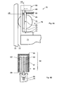
- FIGS. 4A-B and 5A-B show two different uses for one according to the Invention trained electric motor in an elevator.
- FIG. 4A shows an electric motor 90 designed according to the invention, which is in a Elevator 70 is installed.
- the elevator 70 comprises a car 71, which along a Guide surface 72 'is guided on a guide rail 72.
- Fig. 4A is only a part of the elevator 70 in the immediate vicinity of the electric motor 90.
- a drive for moving the cabin 71 along the guide surface 72 'and other common Elevator components are not shown.
- a guide device 75 is provided to guide the cabin 71 along the Guide surface 72 '.
- the guiding device 75 comprises: (i) a bracket 77 mounted on the cab 71; (ii) a Guide member 76 formed as a roller rotatable about a rotation axis 80; (iii) a lever 78 in which the axis of rotation 80 is mounted and which is mounted in the carrier 77 mounted, arranged at one end of the lever 78 axis of rotation 79 is pivotable; (Iv) a rod-shaped guide device 85 which is arranged on the carrier 77 and to Guiding the end of the lever 78 remote from the rotation axis 79; (v) a spring 86, which is arranged between the lever 78 and one end of the guide device 85 and biased such that the guide member 76 with each movement of the car 71 along the guide rails 72 with the guide surface 72 'is brought into contact and with a certain (given in certain limits) force against the respective Guide surface 72 'is pressed.
- the guide member 76 By means of a pivoting movement of the lever 78 to the Rotary axis 79, the guide member 76 can be moved relative to the car 71. in the In the present case, the guide element 76 rolls along with a movement of the car 71 along the guide rail 72 on the respective guide surface 72 'from.
- the electric motor 90 is fixed to the carrier 77 and the lever 76 such that the instantaneous position of the guide member 76 with respect to the cabin 71 by means of Electric motor 90 can be changed electronically controlled.
- FIG. 4B shows the electric motor 90 in a section 4B-4B according to FIG. 4A.
- the electric motor 90 is designed as a linear motor and is essentially like the Electric motors 10 and 20 constructed.
- the electric motor 90 includes a primary part 91 for generating a traveling magnetic field and a secondary part 92 for Provision of a static magnetic field.
- the secondary part 92 corresponds in terms of its construction essentially the secondary parts 12 and 22 of the electric motors 10th or 20.
- the secondary part 92 comprises two devices 93 and 93 ', which, like the Devices 13 and 13 'are constructed and, for example, after the in Figs. 3B-C specified scheme can be realized.
- the Devices 13 and 13 ' ach one arranged on a substrate trace, the supplied with an electric current for generating a static magnetic field is.
- the respective substrates are plate-shaped and have flat surfaces.
- the Devices 93 and 93 ' are arranged parallel to each other and on a support 95, which, as shown in FIG. 4B, has a U-shaped cross-section, fixed in such a way, an air gap is formed between the devices 93 and 93 '.
- the primary part 91 is arranged movable.
- the primary part 91 corresponds with regard to its structure essentially the primary parts 11 and 21 of the Electric motors 10 and 20. It can, for example, after that indicated in FIG. 3A Scheme be realized.
- the traveling magnetic field for example a arranged on a substrate trace, which can be supplied with an alternating current is provided.
- the primary part 91 relative to the secondary part 92 (synchronous with the migratory generated by the primary part 91 Magnetic field) are moved. This movement takes place in the present case in the Longitudinal direction of the guide device 85, as shown in Fig. 4A by a double arrow is indicated.
- the secondary part 92 is on the carrier 77 attached.
- the remote from the axis of rotation 79 end of the lever 78 by means of a connecting element 89 connected to the primary part 91. Accordingly goes during operation of the electric motor 90, a movement of the primary part 91 with a Pivoting movement of the lever 78 about the rotation axis 79 associated.
- a suitable electrical control of the electric motor 90 can thus the guide member 76 relative be moved to the cabin 71. Accordingly, the position of the cab 71 relative to the guide surface 72 'are moved, with which the guide member 76 is in contact.
- the distance between the car 71 and the guide surface 72 'in Range controlled to vary.
- a motor control (not shown) for the Electric motor 90 is provided, which in response to signals from suitable sensors Currents for supplying the primary part 91 and the secondary part 92 and the Devices 93 and 93 ', for example, in terms of their amplitude, their frequency and the layer controls its phase to control the position of the guide member 76 relative to Cabin 71 to influence according to predetermined criteria.
- you can Sensors are provided, which during a drive of the cabin 71 along the Guide surface 72 'oscillations of the car 71, transverse to the direction of movement of Cabin 71 occur, detect.
- These vibrations can be reduced or optionally be suppressed by the motor control the electric motor 90 in Depending on signals from these sensors to movements that led to a Compensation of the vibrations of the cabin 71 lead.
- the elevator 70 according to FIGS. 4A and 4B may, in the context of the invention, be different Modes are modified.
- the electric motor 90 can be so with respect to the guide device 75th be arranged that the primary part 91 stationary with respect to the cabin 71 and the Secondary part 92 together with the guide member 75 relative to the cab 71 movable is. Furthermore, one of the devices 93 or 93 'can be dispensed with. Moreover, the primary part 91 may have a plurality of tracks independently of each other Power can be supplied to the migratory magnetic field with multiple currents produce. These streams can have several different phases.
- the power supply for the primary part must be designed to be multiphase and the Motor control for the electric motor 90 must be suitably adapted to the by the respective conductor tracks of the primary part 91 flowing currents in terms of their Amplitude, their frequency and their phase suitable to control.
- the Carrier 95 for the devices 93 and 93 'made of a soft magnetic material be made to a magnetic flux on the primary part 91 facing away Pages of the devices 93 and 93 'in the carrier 95 to concentrate.
- a plurality of guide devices 75 may be attached to the cabin 71, for example, two in the Longitudinal direction of the respective guide rail 72 spaced guide devices 75.
- the guide rails 72 may also be in addition to those already described Guide surface 72 'further guide surfaces for guiding the car 71 in the Longitudinal direction of the respective guide rail 72 are suitable.
- each Guide rail 72 could, for example, two or three in the longitudinal direction of Guide rail 72 have extending guide surfaces, each adjacent Guide surfaces - based on a cross section of the respective guide rail 72 - in an angle of less than 180 ° (for example, 90 °) are arranged to each other. Accordingly, a plurality of guide devices 75 on the cabin 71 may be so be arranged that the car 71 - as in connection with FIG.
- Vibration degrees of freedom of the cabin 71 can be measured by sensors.
- an engine control can be provided, the the electric motors 90 suitably controls and causes to move to a Compensate for the vibrations.
- the number and arrangement of Guiding devices 75 and the electric motors 90 may correspond to the number of Vibration degrees of freedom to be detected by the engine control to get voted.
- FIG. 5A shows an elevator 100, which is a cabin 102 movable along a path includes.
- FIG. 5B illustrates the elevator 100 in a section 5B-5B according to FIG. 5A.
- a guide rail 103 is disposed on a wall 101 of a hoistway.
- the Cabin is in a movement along the track on the guide rail 103 with conventional guide means, however, which are not shown in Fig. 5A-B, out.
- a trained according to the invention electric motor 110 serves as a drive for movement the car 102 along the guide rail 103.
- the electric motor 110 is a linear motor designed on the basis of in connection with the electric motors 10 and 20 mentioned concepts.
- the electric motor 110 includes a primary part 111 for generation a traveling magnetic field and a secondary part 112 for providing a static magnetic field.
- the primary part 111 and the secondary part 112 are arranged such that the primary part 111 and the secondary part 112 under an effect of the migrating magnetic field relative are movable relative to each other.
- the primary part 111 is arranged such that by means of of the primary part 111 can be generated traveling magnetic field parallel to the path of the cabin emigrated.
- the primary part 111 extends along the entire length of the path of the car 102. It is attached to the guide rail 103.
- the primary part 111 is composed of a plurality of longitudinally along the path of the cabin successively arranged modules, respectively a conductor track arranged on a substrate, wherein the tracks of the various modules for generating the traveling magnetic field with a current are available.
- Each module may, for example, like the primary part 11 of the Electric motor 10 to be constructed.
- the tracks of the various modules can be used in Be connected in series and have a common power supply.
- the tracks The different modules can also have a separate power supply. The latter offers the possibility of the migrating magnetic field - as needed - only in individual sections of the path of the car 102 to produce.
- the secondary part 112 has a shorter extension in the direction of the path of the car 102 as the primary part 111 and is fixed to the cab 102. In the present case is a Connecting element 109 between the secondary part 112 and the car 102nd arranged to the secondary part 112 at a suitable distance from the car 102 to hold.
- the secondary part 112 has - as a comparison with the Fig. 1 B, 2B and 4B indicates - Essentially the same structure as the secondary parts of the electric motors 10, 20 and 90th
- the secondary part 112 comprises two devices 113 and 113 ', which, like the Devices 13 and 13 'are constructed and, for example, after the in Figs. 3B-C specified scheme can be realized. Accordingly, the Devices 113 and 113 'each one arranged on a substrate trace, the supplied with an electric current for generating a static magnetic field is.
- the respective substrates are plate-shaped and have flat surfaces.
- the carrier 115 may also be made of a soft magnetic material Be made of material.
- the secondary part 112 is arranged such that the primary part 111 into the air gap between the devices 113 and 113 'of the secondary part 112 protrudes and not with the Devices 113 and 113 'is brought into contact when the car 102 along the Guide rail 103 is moved.
- the latter assumes that the mentioned Guide means for guiding the cab 103 along the guide rail 103 the to ensure the required degree of precision and rigidity.
- the cab 102 may be moved or held at a predetermined location be suitable by the conductor tracks of the primary part 111 and the secondary part 112 be powered.
- the primary part 111 is driven to enter migratory magnetic field generated, then the car 102 is synchronized with the moving magnetic field along the guide rail 103 moves.
- both the Primary part 111 and the primary part 112 are supplied with a direct current, then For example, the cab 102 may be held at a predetermined location.
- the engine 110 may be designed so that the force that the electric motor 110 in operation on the cabin 102 exercises, sufficient to hold the cabin without further aids.
- the elevator 100 may have no support means for the car 102 (i.e., without ropes or belts). and operated without counterweight.
- the elevator 100 can be modified in many ways within the scope of the invention.
- the Power supply for the tracks of the primary part 111 and the secondary part 112 also be designed such that currents only in the areas of the primary part 111 and the secondary part 112 flow, in which the primary part 111 with the secondary part 112th overlaps. In this way, the power consumption of the electric motor 110 can be reduced become.
- the elevator 100 can be attached to a plurality of guide rails 103 be guided.
- the guide rails may be on different sides of the cab 102 be arranged.
- the cabin 102 may include a plurality of electric motors 110 are driven.
- the primary parts 111 of the various Electric motors 110 disposed on the respective guide rails and the corresponding secondaries 111 are attached to the cab 102, for example according to the concept shown in Figs. 5A and 5B.
- the electric motor 110 can each be replaced by another inventively designed electric motor, the primary part stationary with respect to the cabin 103 and its secondary part stationary with respect to the path of the cab 103 is arranged.
- the extension of the respective primary part along the path can be short compared to the extension be of the corresponding secondary part.
- the mentioned electric motors and the cabin with separate means be guided along the path of the cabin 102.
- the modifications that are for the electric motors 10, 20 and 90 are disclosed analogously to the electric motor 110 transferable.
Landscapes
- Engineering & Computer Science (AREA)
- Physics & Mathematics (AREA)
- Chemical & Material Sciences (AREA)
- Combustion & Propulsion (AREA)
- Electromagnetism (AREA)
- Power Engineering (AREA)
- Linear Motors (AREA)
Abstract
Description
Die Erfindung bezieht sich auf einen Elektromotor gemäss dem Oberbegriff des Anspruchs 1 und einen Aufzug mit einer mittels eines solchen Elektromotors längs einer Bahn bewegbaren Kabine. Ein weiterer Gegenstand der Erfindung ist ein Aufzug mit einer längs mindestens einer Führungsfläche bewegbaren Kabine, mit einem Führungselement, welches an der Kabine bewegbar angeordnet und mit der Führungsfläche in Kontakt gebracht ist, und mit einem Elektromotor zur Bewegung des Führungselements relativ zu der Kabine.The invention relates to an electric motor according to the preamble of Claim 1 and an elevator with a means of such an electric motor along a Railway movable cabin. Another object of the invention is an elevator with a along at least one guide surface movable cabin, with a guide element, which is arranged movably on the cabin and in contact with the guide surface is brought, and with an electric motor for moving the guide member relative to the cabin.
Elektromotoren der vorstehend genannten Art sind aus den europäischen Patentanmeldungen EP 0 949 748 A1 und EP 0 949 749 A1 bekannt. In diesen Patentanmeldungen sind Linearmotoren beschrieben, die jeweils einen Primärteil zur Erzeugung eines wandernden Magnetfeldes und einen Sekundärteil zur Bereitstellung eines statischen Magnetfeldes aufweisen, wobei der Sekundärteil und der Primärteil räumlich durch einen Luftspalt getrennt sind und unter einer Wirkung des wandernden Magnetfeldes relativ zueinander bewegbar sind. Zur Erzeugung des wanderndes Magnetfeldes umfasst der Primärteil mehrere flache, eisenlose Spulen, die als gedruckte Schaltungen auf ein isolierendes Substrat aufgebracht sind. Zur Bereitstellung des statischen Magnetfelds sind im Sekundärteil mehrere Permanentmagnete derart angeordnet sind, dass an einer Oberfläche des Sekundärteils eine periodische magnetische Struktur ausgebildet ist. Als Spulen für den Primärteil sind mehrere Konfigurationen vorgeschlagen, die für eine Versorgung mit Wechselstrom mit einer Phase oder mit mehreren Phasen ausgebildet sind. Diese Linearmotoren haben den Nachteil, dass der Sekundärteil wegen seiner Bestückung mit Permanentmagneten ein hohes Gewicht aufweist. Weiterhin führt die Verwendung von Permanentmagneten zu hohen Stückkosten, da einerseits Permanentmagnete in der Regel verhältnismässig teuer sind und weiterhin die Herstellung eines aus einer Vielzahl von Permanentmagneten zusammengesetzten Sekundärteils aufwändig und somit mit hohen Kosten verbunden ist. Der Aufwand bei der Herstellung des Sekundärteils steigt insbesondere - mit entsprechenden Folgen für die Herstellungskosten - wenn die Permanentmagnete in ihren Abmessungen möglichst genau übereinstimmen müssen und mit möglichst grosser Präzision derart parallel nebeneinander angeordnet werden sollen, dass ihre Oberflächen eine ebene Fläche bilden. Letzteres ist relevant bei Präzisionsmotoren und bei hocheffizienten Motoren, die einen engen Luftspalt zwischen dem Primärteil und dem Sekundärteil aufweisen.Electric motors of the type mentioned above are from the European Patent applications EP 0 949 748 A1 and EP 0 949 749 A1. In these Patent applications are described linear motors, each having a primary part for Generation of a traveling magnetic field and a secondary part for the provision a static magnetic field, wherein the secondary part and the primary part spatially separated by an air gap and under an effect of the wandering Magnetic field are relatively movable. To generate the migratory Magnetic field, the primary part comprises several flat, ironless coils, which are printed as Circuits are applied to an insulating substrate. To provide the static magnetic field are in the secondary part a plurality of permanent magnets such are arranged, that on a surface of the secondary part a periodic magnetic structure is formed. As coils for the primary part are several Configurations proposed for a supply of alternating current with a Phase or are formed with multiple phases. These linear motors have the Disadvantage that the secondary part because of its assembly with permanent magnets has high weight. Furthermore, the use of permanent magnets leads to high unit costs, on the one hand permanent magnets usually relatively expensive are and continue to manufacture one of a variety of permanent magnets Complex secondary part consuming and thus associated with high costs. The effort in the production of the abutment increases in particular - with corresponding consequences for the manufacturing costs - if the permanent magnets in Their dimensions must match as closely as possible and with the largest possible Precision so parallel to each other should be arranged side by side, that their surfaces form a flat surface. The latter is relevant in precision motors and in high-efficiency motors, which have a narrow air gap between the primary part and the Secondary part have.
In der europäischen Patentanmeldung EP 0 785 162 A1 ist ein Aufzug mit einem Antriebssystem für eine Kabine auf der Basis eines als Synchronmotor betriebenen Linearmotors offenbart. Der Linearmotor weist einen Primärteil zur Erzeugung eines wandernden Magnetfeldes und einen Sekundärteil zur Bereitstellung eines statischen Magnetfeldes auf. Der Sekundärteil besteht aus einer Vielzahl von Permanentmagneten, die an einer Wand eines Aufzugsschachtes längs der Bahn der Kabine angeordnet sind. Der Primärteil besteht aus Spulen, die an einer Seite der Kabine angeordnet sind. Diese Konstruktion des Sekundärteils führt zu hohen Material- und Herstellungskosten und die Installation des Sekundärteils im Aufzugsschacht ist wegen des grossen Gewichts der Permanentmagnete aufwändig. Da der Sekundärteil permanent hohe statische Magnetfelder auf der gesamten Länge des Aufzugsschachts bereitstellt, müssen bei der Installation des Sekundärteils und allgemein bei Wartungsarbeiten im Aufzugsschacht geeignete Vorsichtsmassnahmen getroffen werden, um unerwünschte Wirkungen der Magnetfelder zu vermeiden.European Patent Application EP 0 785 162 A1 discloses an elevator with a Drive system for a cabin based on a synchronous motor Linear motor disclosed. The linear motor has a primary part for generating a wandering magnetic field and a secondary to provide a static Magnetic field on. The secondary part consists of a large number of permanent magnets, which are arranged on a wall of an elevator shaft along the path of the cabin. The primary part consists of coils which are arranged on one side of the cabin. These Construction of the secondary part leads to high material and manufacturing costs and the Installation of the secondary part in the elevator shaft is due to the large weight of the Permanent magnets elaborate. Since the secondary part permanently high static Magnetic fields provided along the entire length of the hoistway, at the Installation of the secondary part and generally during maintenance work in the hoistway appropriate precautions are taken to avoid adverse effects To avoid magnetic fields.
In US 2003/0000778 A1 ist ein Aufzug offenbart, dessen Kabine mittels eines Linearmotors bewegt werden kann. Der Sekundärteil des Linearmotors kann entweder gewickelte Spulen oder eine Kombination von solchen Spulen und Permanentmagneten umfassen. Derartige Spulen sind in der Regel auf einen Eisenkern gewickelt. Der Linearmotor hat deshalb ein hohes Gewicht und ein grosses Volumen. Seine Herstellung ist ferner aufwändig, da er aus vielen Einzelteilen zusammengesetzt werden muss.In US 2003/0000778 A1 an elevator is disclosed, the car by means of a Linear motor can be moved. The secondary part of the linear motor can either wound coils or a combination of such coils and permanent magnets include. Such coils are usually wound on an iron core. Of the Linear motor therefore has a high weight and a large volume. His production is also expensive because it has to be composed of many individual parts.
Es ist die Aufgabe der vorliegenden Erfindung, die genannten Nachteile der bekannten Elektromotoren zu vermeiden und einen Elektromotor zu schaffen, der kompakt aufgebaut ist, ein geringes Gewicht aufweist und die Voraussetzung für eine kostengünstige Herstellung mit sich bringt. Der Elektromotor soll - geeignet dimensioniert - in einem Aufzug als Antrieb zur Bewegung einer Kabine oder zur Bewegung eines Führungselements relativ zu einer Kabine verwendbar sein. It is the object of the present invention, the mentioned disadvantages of the known To avoid electric motors and to create an electric motor that has a compact design is lightweight, and the prerequisite for a cost-effective Manufacturing brings with it. The electric motor should - suitably dimensioned - in one Elevator as a drive for moving a cabin or for moving a Guide member be used relative to a cabin.
Diese Aufgabe wird gelöst durch einen Elektromotor mit den Merkmalen des Anspruchs 1. Die von diesem Anspruch abhängigen Ansprüche definieren vorteilhafte Ausführungsformen dieses Elektromotors.This object is achieved by an electric motor having the features of claim 1. The claims dependent on this claim define advantageous ones Embodiments of this electric motor.
Der erfindungsgemässe Elektromotor weist einen Primärteil zur Erzeugung eines wandernden Magnetfeldes und einem Sekundärteil zur Bereitstellung eines statischen Magnetfeldes auf, wobei der Sekundärteil und der Primärteil unter einer Wirkung des wandernden Magnetfeldes relativ zueinander bewegbar sind. Der Sekundärteil umfasst eine auf einem Substrat angeordnete Leiterbahn, die zwecks Erzeugung des statischen Magnetfeldes mit einem elektrischen Strom versorgbar ist.The electric motor according to the invention has a primary part for generating a migratory magnetic field and a secondary to provide a static Magnetic field, wherein the secondary part and the primary part under an effect of migratory magnetic field are relatively movable. The secondary part comprises a conductor track arranged on a substrate, which is used to generate the static Magnetic field can be supplied with an electric current.
Die spezielle Konstruktion des Sekundärteils ermöglicht die Bereitstellung eines statischen Magnetfelds ohne Verwendung von Permanentmagneten. Das zum Betrieb des Elektromotors benötigte statische Magnetfeld wird elektromagnetisch erzeugt, indem durch die Leiterbahn ein elektrischer Strom geschickt wird. Alle Nachteile, die die Verwendung von Permanentmagneten mit sich bringt, sind somit vermieden.The special design of the abutment allows the provision of a static magnetic field without using permanent magnets. That to the operation The static magnetic field required by the electric motor is generated electromagnetically by an electrical current is sent through the track. All the disadvantages that the Use of permanent magnets entails are thus avoided.
Erfindungsgemäss umfasst der Sekundärteil als ein wesentliches Grundelement ein Substrat, welches als Träger der Leiterbahn dient und für die gewünschte mechanische Stabilität des Sekundärteils sorgt. Dadurch ist die Voraussetzung geschaffen für die Konstruktion eines Sekundärteils, der kompakt ist, ein geringes Gewicht aufweist und kostengünstig herstellbar ist. Das Substrat und die Leiterbahn können als eine Schichtstruktur ausgebildet sein. Die Leiterbahn kann beispielsweise aus einer dünnen, elektrisch leitfähigen Schicht gebildet werden, die auf das Substrat aufgebracht und gegebenenfalls geeignet strukturiert wird. Im Hinblick auf die Konstruktion und die Herstellung des Sekundärteils sind dabei die Technologien anwendbar, die für gedruckte Schaltungen entwickelt wurden. Dies erlaubt eine kostengünstige Fertigung.According to the invention, the secondary part comprises as an essential basic element Substrate, which serves as a carrier of the conductor and for the desired mechanical Stability of the abutment ensures. This creates the conditions for the Construction of a secondary part, which is compact, lightweight and has is inexpensive to produce. The substrate and the conductor can be used as a Layer structure be formed. For example, the track can be made of a thin, electrically conductive layer are formed, which are applied to the substrate and optionally structured appropriately. With regard to the construction and the Production of the abutment are applicable to the technologies that are printed for Circuits were developed. This allows a cost-effective production.
Das Substrat kann aus einem Material hoher Festigkeit gefertigt werden. Dies ermöglicht die Verwendung dünner Substrate mit einer grossen Oberfläche. Somit kann ein Sekundärteil geschaffen werden, der in einer Dimension extrem schmal ist und somit durch einen besonders engen Luftspalt zwischen zwei Polen eines Polpaars eines Primärteils bewegt werden kann. Da die Leiterbahn aus einer dünnen leitfähigen Schicht gebildet werden kann, ist es möglich, einen Sekundärteil zu schaffen, der im Bereich der Leiterbahn eine relativ glatte Oberfläche aufweist. Dadurch wird es möglich, einen Elektromotor zu schaffen, bei dem der Sekundärteil in einem besonders geringen Abstand zum Primärteil angeordnet werden kann und der deshalb mit hoher Effizienz betreibbar ist.The substrate may be made of a high strength material. this makes possible the use of thin substrates with a large surface area. Thus, a Abutment are created, which is extremely narrow in one dimension and thus through a particularly narrow air gap between two poles of a pole pair of a Primary part can be moved. Because the trace is made of a thin conductive layer can be formed, it is possible to create a secondary part in the field of Track has a relatively smooth surface. This will make it possible to get one To provide electric motor, in which the secondary part in a particularly small distance can be arranged to the primary part and therefore operated with high efficiency is.
Der Elektromotor kann in einer Vielzahl von Geometrien realisiert sein. Die Form des Substrats kann - jeweils angepasst an die Form des Primärteils - entsprechend gewählt werden. Der Elektromotor kann beispielsweise als rotierender Motor konstruiert sein. Der Elektromotor kann aber auch für andere Bewegungsarten ausgelegt sein, beispielsweise als Linearmotor. Das Substrat kann beispielsweise die Form eines Zylinders aufweisen. In diesem Fall kann die Leiterbahn beispielsweise auf dem Mantel des Zylinders angeordnet werden, um einen um die Längsachse des Zylinders rotierbaren Sekundärteil zu bilden. Der Sekundärteil kann auch als eine flache, um eine Achse rotierbare Scheibe ausgebildet sein. In diesem Fall stehen die Grundflächen der Scheibe für die Anordnung der Leiterbahn zur Verfügung. Alternativ, beispielsweise im Falle eines Linearmotors, kann der Sekundärteil auch als flache, längs einer Bahn mit einer endlichen Länge bewegbare Platte ausgebildet sein, wobei die Grundflächen der Platte für die Anordnung der Leiterbahn zur Verfügung stehen.The electric motor can be realized in a variety of geometries. The shape of the Substrate can - depending on the shape of the primary part - selected accordingly become. The electric motor may be constructed, for example, as a rotating motor. Of the Electric motor can also be designed for other types of movement, for example as a linear motor. The substrate may, for example, have the shape of a cylinder. In In this case, the conductor can for example be arranged on the jacket of the cylinder be to form a rotatable about the longitudinal axis of the cylinder secondary part. The secondary part can also be designed as a flat disk rotatable about an axis be educated. In this case, the base areas of the disc stand for the arrangement the conductor track available. Alternatively, for example in the case of a linear motor, The abutment may also be considered flat, along a path of finite length be formed movable plate, wherein the base surfaces of the plate for the arrangement the track are available.
Der Sekundärteil einer Ausführungsform des erfindungsgemässen Elektromotors kann als eine Schichtstruktur, hergestellt durch Aufbringen verschiedener Schichten auf das Substrat, konzipiert sein. Die Schichten können nacheinander aufgebracht werden und gegebenenfalls geeignet strukturiert werden. Auf diese Weise können auf dem Substrat dreidimensionale Strukturen aus Materialien mit unterschiedlichen Eigenschaften aufgebracht werden. Einzelne Schichten können aus einem elektrisch isolierenden Material bestehen oder Bereiche aus einem elektrisch isolierenden Material umfassen. Die Leiterbahn kann aus Leiterbahnabschnitten, die jeweils in verschiedenen Schichten der Schichtstruktur ausgebildet sind, zusammengesetzt sein. Einzelne Abschnitte der Leiterbahn können sich beispielsweise in verschiedenen Ebenen überkreuzen und im Bereich der Überkreuzung durch eine elektrisch isolierende Schicht getrennt sein. Weiterhin besteht die Möglichkeit, einzelne Abschnitte der Leiterbahn in verschiedenen durch eine Zwischenschicht getrennte Schichten anzuordnen und in der Zwischenschicht einen elektrisch leitfähigen Bereich vorzusehen, der eine elektrische Verbindung zwischen diesen Abschnitten der Leiterbahn herstellt.The secondary part of an embodiment of the electric motor according to the invention can be described as a layered structure made by applying various layers to the Substrate, be conceived. The layers can be applied one after the other and if appropriate, be structured appropriately. That way, on the substrate three-dimensional structures of materials with different properties be applied. Individual layers can be made of an electrically insulating material Material consist or areas of an electrically insulating material. The trace may consist of trace segments, each in different layers the layer structure are formed, be composed. Individual sections of the For example, interconnects can cross over in different planes and in the Be separated region of the crossover by an electrically insulating layer. Furthermore, there is the possibility of individual sections of the track in different to arrange separate layers by an intermediate layer and in the intermediate layer to provide an electrically conductive region having an electrical connection between produces these sections of the track.
Schichten der genannten Art können auch auf beiden Seiten des Substrats aufgebracht und gegebenenfalls strukturiert werden. Bei dem Sekundärteil einer weiteren Ausführungsform des erfindungsgemässen Elektromotors ist beispielsweise vorgesehen, dass ein erster Teil der Leiterbahn an einer ersten Oberfläche des Substrats und ein zweiter Teil der Leiterbahn an einer zweiten Oberfläche des Substrats ausgebildet ist, wobei eine elektrische Verbindung zwischen dem ersten und dem zweiten Teil hergestellt ist. Dies ermöglicht es, der Leiterbahn eine besonders komplexe geometrische Struktur zu verleihen.Layers of the type mentioned can also be applied on both sides of the substrate and possibly structured. In the secondary part of another Embodiment of the inventive electric motor is provided, for example, that a first part of the conductor track on a first surface of the substrate and a second part of the conductor track is formed on a second surface of the substrate, wherein an electrical connection is made between the first and second parts is. This allows the trace to have a particularly complex geometric structure to lend.
Bei einer Variante des Sekundärteils kann beispielsweise mindestens ein Abschnitt der Leiterbahn die Form einer Spule aufweisen, wobei jede Spule eine oder mehrere Windungen umfasst. Die Spule kann auf einer Seite des Substrats angeordnet sein, sie kann aber auch aus verschiedenen Abschnitten der Leiterbahn zusammengesetzt sein, die auf verschiedenen Seiten des Substrats angeordnet sind und elektrisch miteinander verbunden sind.In a variant of the secondary part, for example, at least a portion of Conductor having the form of a coil, each coil one or more Includes turns. The coil may be disposed on one side of the substrate but can also be composed of different sections of the track, which are arranged on different sides of the substrate and electrically with each other are connected.
In einer weiteren Variante des Sekundärteils können mehrere seriell angeordnete Abschnitte der Leiterbahn jeweils die Form einer Spule haben, wobei die Spulen derart ausgebildet sind, dass bei einem Stromfluss durch die Leiterbahn benachbarte Spulen jeweils Magnetfelder mit unterschiedlicher Polarität erzeugen. Beispielsweise kann die Leiterbahn derart angeordnet sein, dass bei einer Versorgung der Leiterbahn mit einem Gleichstrom an einer Oberfläche des Sekundärteils ein statisches Magnetfeld erzeugt wird, dessen Polarität eine periodische Umkehr der Polarität längs der Richtung, in der der Sekundärteil relativ zum Primärteil bewegbar ist, aufweist. Auf diese Weise kann ein Sekundärteil zur Bereitstellung einer grossen Zahl magnetischer Pole ausgebildet werden. Bei einer geeigneten Anordnung der Leiterbahn kann die auf dem Substrat zur Verfügung stehende Fläche effizient genutzt werden. Dies ist relevant für die Optimierung der Effizienz des Elektromotors und die Genauigkeit, mit der die Bewegung des Sekundärteils relativ zum Primärteil während des Betriebs des Motors kontrolliert werden kann.In a further variant of the secondary part, a plurality of serially arranged Each section of the conductor track has the form of a coil, the coils being such are formed such that at a current flow through the conductor track adjacent coils each generate magnetic fields with different polarity. For example, the Conductor be arranged such that in a supply of the conductor with a DC generated at a surface of the secondary part of a static magnetic field whose polarity is a periodic reversal of the polarity along the direction in which the secondary part is movable relative to the primary part has. This way you can Abutment be designed to provide a large number of magnetic poles. With a suitable arrangement of the conductor can be made available on the substrate standing area can be used efficiently. This is relevant to the optimization of Efficiency of the electric motor and the accuracy with which the movement of the secondary part relative to the primary part during operation of the engine can be controlled.
In einer Weiterentwicklung des Sekundärteils können zur Erzeugung des statischen Magnetfelds auch mehrere Leiterbahnen vorgesehen werden, die unabhängig voneinander mit einem elektrischen Strom versorgbar sind. Mit einem derart ausgebildeten Sekundärteil kann ein statisches Magnetfeld mit einer besonders grossen Energiedichte erzeugt werden. Auf der Grundlage dieses Konzepts kann die maximale Kraft, mit der der Sekundärteil während des Betriebs des Motors relativ zum Primärteil bewegt wird, zusätzlich erhöht werden. In a further development of the secondary part can be used to generate the static Magnetic field also provided several tracks, which are independent from each other with an electric current can be supplied. With such a thing trained secondary part can be a static magnetic field with a particularly large Energy density can be generated. On the basis of this concept, the maximum Force with which the secondary part during operation of the engine relative to the primary part is moved, additionally increased.
Eine Weiterentwicklung des erfindungsgemässen Elektromotors weist einen Primärteil auf, der eine auf einem Substrat angeordnete Leiterbahn umfasst, wobei diese Leiterbahn zwecks Erzeugung des wandernden Magnetfeldes mit einem elektrischen Strom, dessen Stromstärke mit der Zeit variiert, versorgbar ist. Bei dieser Konstruktion des Elektromotors ist der Primärteil nach demselben technologischen Konzept realisierbar, auf dem erfindungsgemäss der Design des Sekundärteils beruht. Zur Erzeugung des wandernden Magnetfelds ist somit eine elektrische Struktur vorgesehen, die als eine Schichtstruktur realisierbar ist, beispielsweise durch Aufbringung von dünnen Schichten auf ein Substrat und gegebenenfalls durch eine Strukturierung dieser Schichten. Beispielswiese können mehrere seriell angeordnete Abschnitte der Leiterbahn jeweils die Form einer Spule haben, wobei die Spulen derart ausgebildet sind, dass bei einem Stromfluss durch die Leiterbahn benachbarte Spulen jeweils Magnetfelder mit unterschiedlicher Polarität erzeugen. Somit sind sowohl der Primärteil als auch der Sekundärteil realisierbar als Schichtstrukturen, die dünne auf ein Substrat aufgebrachte elektrisch leitfähige Bereiche umfassen. Demnach sind sowohl der Primärteil als auch der Sekundärteil mit Techniken herstellbar, die für die Fabrikation von gedruckten Schaltungen im Einsatz sind.A further development of the electric motor according to the invention has a primary part on, which comprises a substrate arranged on a conductor track, said conductor track for generating the traveling magnetic field with an electric current whose Current varies with time, can be supplied. In this construction of the electric motor the primary part can be realized according to the same technological concept on which according to the invention, the design of the secondary part is based. To generate the wandering Magnetic field is thus provided an electrical structure, which serves as a layer structure can be realized, for example, by applying thin layers on a substrate and optionally by structuring these layers. Example meadow a plurality of serially arranged sections of the conductor track each in the form of a coil have, wherein the coils are formed such that at a current flow through the Conductor adjacent coils each magnetic fields with different polarity produce. Thus, both the primary part and the secondary part can be realized as Layer structures, the thin applied to a substrate electrically conductive areas include. Accordingly, both the primary part and the secondary part are with techniques manufacturable, which are used for the manufacture of printed circuits.
Diese Variante des erfindungsgemässen Elektromotors hat mehrere Vorteile. Für den Primärteil und den Sekundärteil können jeweils dünne Substrate, die zudem ein geringes Gewicht aufweisen, verwendet werden. Im Gegensatz zu konventionellen Motorkonstruktionen werden im vorliegenden Fall für die Erzeugung des magnetischen Wanderfeldes bzw. die Erzeugung des statischen Magnetfelds weder ein ferromagnetischer Kern noch gewickelte Spulen noch Permanentmagnete benötigt. Diese Variante des Elektromotors kann deshalb besonders leicht, kompakt und kostengünstig gebaut werden. Die Möglichkeit, im Rahmen der Erfindung den Primärteil und den Sekundärteil ohne ferromagnetische Kerne und ohne Permanentmagnete realisieren zu können, vereinfacht auch die Kontrolle der Bewegung des Sekundärteils während des Betriebs des Elektromotors, da die Störkräfte, die bei konventionellen Elektromotoren zwischen einem (in der Regel mit Zähnen und Nuten versehenen) ferromagnetischen Kern und dem Sekundärteil auftreten, entfallen. Wegen des geringen Gewichts ist der Motor besonders gut geeignet zur Steuerung von schnellen Bewegungen. Da bei einer Steuerung des Motors nur geringe Massen beschleunigt werden müssen, können schnelle Bewegungen effizient und präzise gesteuert werden.This variant of the electric motor according to the invention has several advantages. For the Primary part and the secondary part can each thin substrates, which also has a low Have weight used. Unlike conventional Motor designs are used in the present case for the production of magnetic Wanderfeldes or the generation of the static magnetic field neither a ferromagnetic core nor wound coils nor permanent magnets needed. These Variant of the electric motor can therefore be particularly lightweight, compact and cost-effective be built. The possibility, in the context of the invention, the primary part and the Secondary part without ferromagnetic cores and without permanent magnets realize too can also simplify the control of the movement of the abutment during the Operation of the electric motor, as the disturbance forces, in conventional electric motors between a (usually with teeth and grooves provided) ferromagnetic Core and the secondary part occur, omitted. Because of the low weight is the Motor particularly suitable for controlling fast movements. Because at one Control of the engine only small masses need to be accelerated fast movements are controlled efficiently and precisely.
Bei einer Weiterentwicklung der vorstehend genannten Variante des erfindungsgemässen Elektromotors ist vorgesehen, dass der Primärteil mehrere auf einem Substrat angeordnete Leiterbahnen umfasst und dass jede dieser Leiterbahnen zwecks Erzeugung des wandernden Magnetfeldes jeweils mit einem elektrischen Strom, dessen Stromstärke mit der Zeit variiert, versorgbar ist. Da jede der Leiterbahnen unabhängig mit einer Stromquelle angesteuert werden können, kann nach diesem Konzept ein mehrphasig ansteuerbarer Elektromotor entworfen werden.In a further development of the aforementioned variant of the inventive Electric motor is provided that the primary part several on a substrate arranged conductor tracks and that each of these tracks for the purpose of generating of the migrating magnetic field, each with an electric current whose current strength varies with time, is supplyable. Since each of the tracks independently with a Power source can be controlled, according to this concept, a multi-phase controllable electric motor are designed.
Der erfindungsgemässe Elektromotor kann auch in einem Aufzug als Antrieb für eine längs einer Bahn bewegbare Kabine verwendet werden. Der Elektromotor kann in dem Aufzug beispielsweise derart eingebaut sein, dass der Primärteil ortsfest längs der Bahn und der Sekundärteil an der Kabine angeordnet ist. Alternativ kann der Sekundärteil ortsfest längs der Bahn und der Primärteil an der Kabine angeordnet sein. Weiterhin kann der Aufzug mit Mitteln zur Führung der Kabine längs der Bahn ausgestattet und der Primärteil und der Sekundärteil derart an diesen Mitteln angeordnet sein, dass der Primärteil und der Sekundärteil in einem Abstand zueinander geführt sind, wenn die Kabine längs der Bahn bewegt wird. Letzteres hat den Vorteil, dass jede Bewegung des Elektromotors und jede Bewegung der Kabine durch eine gemeinsame Führung kontrolliert ist. Eine separate Führung für den Primärteil bzw. den Sekundärteil des Elektromotors kann auf diese Weise eingespart werden.The electric motor according to the invention can also be used in an elevator as a drive for a along a path movable cabin can be used. The electric motor can in the Elevator, for example, be installed such that the primary part stationary along the track and the secondary part is arranged on the cabin. Alternatively, the secondary part fixedly arranged along the track and the primary part to the cabin. Furthermore, can the elevator equipped with means for guiding the cabin along the track and the Primary part and the secondary part to be arranged on these means that the Primary part and the secondary part are guided at a distance to each other when the Cabin is moved along the path. The latter has the advantage that every movement of the Electric motor and every movement of the cabin through a common leadership is controlled. A separate guide for the primary part or the secondary part of Electric motor can be saved in this way.
In einem Aufzug, welcher eine längs mindestens einer Führungsfläche bewegbare Kabine und ein Führungselement, welches an der Kabine bewegbar angeordnet und mit der Führungsfläche in Kontakt gebracht ist, umfasst, kann der erfindungsgemässe Elektromotor auch als Antrieb zur Bewegung des Führungselements relativ zur Kabine verwendet werden. Der Elektromotor kann dabei derart installiert sein, dass der Primärteil zusammen mit dem Führungselement bewegbar und der Sekundärteil ortsfest bezüglich der Kabine angeordnet ist oder dass der Sekundärteil zusammen mit dem Führungselement bewegbar und der Primärteil ortsfest bezüglich der Kabine angeordnet ist. Weiterhin kann eine Steuerung für den Elektromotor zur Reduktion von Schwingungen der Kabine, die während einer Bewegung der Kabine auftreten können, in den Aufzug integriert sein.In an elevator, which is a cabin movable along at least one guide surface and a guide member which is movably arranged on the cab and with the Guide surface is brought into contact, can, according to the invention Electric motor also as a drive for moving the guide member relative to the cabin be used. The electric motor can be installed in such a way that the primary part movable together with the guide element and the secondary part stationary relative the cab is arranged or that the secondary part together with the Guide element movable and arranged the primary part stationary with respect to the cabin is. Furthermore, a control for the electric motor for the reduction of vibrations the cabin, which can occur during a movement of the cabin, in the elevator be integrated.
Im Folgenden werden Ausführungsbeispiele der Erfindung anhand verschiedener schematischer Figuren erläutert. Es zeigen:
- Fig. 1A:
- Eine Ansicht eines erfindungsgemässen Elektromotors, mit einem Primärteil und einem Sekundärteil, wobei der Primärteil relativ zum Sekundärteil bewegbar ist;
- Fig. 1 B:
- den Elektromotor gemäss Fig. 1 A in
einem Schnitt 1B-1B; - Fig. 2A:
- eine Ansicht eines anderen erfindungsgemässen Elektromotors, mit einem Primärteil und einem Sekundärteil, wobei der Sekundärteil relativ zum Primärteil bewegbar ist;
- Fig. 2B:
- den Elektromotor gemäss Fig. 2A in
einem Schnitt 2B-2B; - Fig. 3A:
- den Primärteil gemäss Fig. 1A in einer detaillierteren Darstellung;
- Fig. 3B:
- den Sekundärteil gemäss Fig. 1A in einer detaillierteren Darstellung;
- Fig. 3C:
- den Sekundärteil gemäss Fig. 3B in
einem Schnitt 3C-3C; - Fig. 4A:
- einen Aufzug mit einer Kabine und einem Führungselement zur Führung der Kabine und mit einem erfindungsgemässen Elektromotor zur Bewegung des Führungselements relativ zur Kabine;
- Fig. 4B:
- den Elektromotor gemäss Fig. 4A in
einem Schnitt 4B-4B; - Fig. 5A:
- einen Aufzug mit einer Kabine und einem erfindungsgemässen Elektromotor als Antrieb zur Bewegung der Kabine;
- Fig. 5B:
- den Aufzug gemäss Fig. 5A in
einem Schnitt 5B-5B.
- Fig. 1A:
- A view of an inventive electric motor, comprising a primary part and a secondary part, wherein the primary part is movable relative to the secondary part;
- Fig. 1B:
- the electric motor according to FIG. 1 A in a
section 1B-1B; - Fig. 2A:
- a view of another inventive electric motor, comprising a primary part and a secondary part, wherein the secondary part is movable relative to the primary part;
- Fig. 2B:
- the electric motor according to FIG. 2A in a
section 2B-2B; - Fig. 3A:
- the primary part according to Fig. 1A in a more detailed representation;
- Fig. 3B:
- the secondary part according to Fig. 1A in a more detailed representation;
- 3C:
- the secondary part according to FIG. 3B in a
section 3C-3C; - Fig. 4A:
- an elevator with a cabin and a guide element for guiding the cabin and with an electric motor according to the invention for moving the guide element relative to the cabin;
- 4B:
- the electric motor according to FIG. 4A in a
section 4B-4B; - Fig. 5A:
- an elevator with a cabin and an inventive electric motor as a drive for moving the car;
- Fig. 5B:
- the elevator according to FIG. 5A in a
section 5B-5B.
Die Fig. 1A zeigt einen Elektromotor 10 gemäss der Erfindung, der einen Primärteil 11 zur
Erzeugung eines wandernden Magnetfeldes und einen Sekundärteil 12 zur Bereitstellung
eines statischen Magnetfeldes umfasst. Die Fig. 1 B zeigt den Elektromotor 10 in einem
Schnitt 1B-1B gemäss Fig. 1 A. Fig. 1A shows an
Die Fig. 2A zeigt einen Elektromotor 20 gemäss der Erfindung, der einen Primärteil 21 zur
Erzeugung eines wandernden Magnetfeldes und einen Sekundärteil 22 zur Bereitstellung
eines statischen Magnetfeldes umfasst. Die Fig. 2B zeigt den Elektromotor 20 in einem
Schnitt 2B-2B gemäss Fig. 2A.Fig. 2A shows an
Die Elektromotoren 10 und 20 sind beide als Linearmotor konzipiert. Der Primärteil 11 und
der Sekundärteil 12 bzw. der Primärteil 21 und der Sekundärteil 22 sind jeweils so
ausgebildet, dass der Primärteil 11 relativ zum Sekundärteil 12 bzw. der Primärteil 21
relativ zum Sekundärteil 22 in der Z-Richtung eines Koordinatensystems XYZ bewegbar
sind, wie in Fig. 1A durch einen Doppelpfeil am Primärteil 11 und in Fig. 2A durch einen
Doppelpfeil am Sekundärteil 22 angedeutet ist.The
Die Elektromotoren 10 und 20 unterscheiden sich im wesentlichen durch das Mass der
Längserstreckung der Primärteile 11 bzw. 21 und der Sekundärteile 12 bzw. 22 in der
jeweiligen Z-Richtung. Im Falle des Elektromotors 10 weist der Primärteil 11 im Vergleich
zum Sekundärteil 12 eine geringere Erstreckung in Z-Richtung auf. Der Elektromotor 10
ist daher bevorzugt verwendbar in Anwendungen, bei denen der Primärteil 11 (im
Gegensatz zum Sekundärteil 12) um eine relativ grosse Distanz bewegt werden soll. Im
Falle des Elektromotors 20 hingegen weist der Primärteil 21 im Vergleich zum
Sekundärteil 22 eine grössere Erstreckung in Z-Richtung auf. Der Elektromotor 20 ist
daher bevorzugt verwendbar in Anwendungen, bei denen der Sekundärteil 22 (im
Gegensatz zum Primärteil 21) um eine relativ grosse Distanz bewegt werden soll.The
Der Sekundärteil 12 weist zwei Vorrichtungen 13, 13', die die Form einer rechteckigen
Platte haben und parallel zur Z-Richtung derart in einem Abstand zueinander angeordnet
sind, dass sie einen Luftspalt 18 der Breite W begrenzen. Die Vorrichtungen 13 und 13'
sind jeweils an Trägern 15 befestigt, die ihrerseits an einer Grundplatte 16 fixiert sind. Der
Primärteil 11 ist derart geformt und derart angeordnet, dass er in dem Luftspalt 18 in der
Z-Richtung bewegbar ist. Eine konventionelle (in den Fig. 1A und 1 B nicht dargestellte)
Führung ist vorgesehen, um den Primärteil 11 bei einer Bewegung relativ zum
Sekundärteil 12 in der Z-Richtung zu führen. Die Vorrichtungen 13 und 13' umfassen
jeweils elektromagnetische Mittel, die im Folgenden im Zusammenhang mit den Fig. 3B-C
noch detaillierter beschrieben werden und jeweils zur Bereitstellung eines statischen
Magnetfeldes dienen. Dieses Magnetfeld wird in der Regel so erzeugt, dass es im
Luftspalt 18, unter Umständen aber auch auf den dem Luftspalt 18 abgewandten Seiten
der Vorrichtungen 13 und 13' präsent ist. Um auf der dem Luftspalt abgewandten Seiten
der Vorrichtungen 13 und 13' einen magnetischen Fluss auf einen möglichst kleinen
Raum zu konzentrieren, können die Träger 15 aus einem weichmagnetischen Material
gefertigt sein.The
Der Sekundärteils 22 ist im Hinblick auf seine Struktur und seine Funktion analog zum
Sekundärteil 12 ausgebildet.The
Der Sekundärteil 22 weist zwei Vorrichtungen 23, 23', die die Form einer rechteckigen
Platte haben und parallel zur Z-Richtung derart in einem Abstand zueinander angeordnet
sind, dass sie einen Luftspalt 28 der Breite W begrenzen. Die Vorrichtungen 23 und 23'
sind jeweils an Trägern 25 befestigt, die ihrerseits an einer Grundplatte 26 fixiert sind. Der
Primärteil 21 ist derart geformt und derart angeordnet, dass er in dem Luftspalt 28 in der
Z-Richtung bewegbar ist. Eine konventionelle (in den Fig. 2A und 2B nicht dargestellte)
Führung ist vorgesehen, um den Sekundärteil 22 bei einer Bewegung relativ zum
Primärteil 21 in der Z-Richtung zu führen. Die Vorrichtungen 23 und 23' umfassen jeweils
elektromagnetische Mittel, die im Folgenden im Zusammenhang mit den Fig. 3B-C noch
detaillierter beschrieben werden und jeweils zur Bereitstellung eines statischen
Magnetfeldes dienen. Dieses Magnetfeld wird in der Regel so erzeugt, dass es im
Luftspalt 28, unter Umständen aber auch auf den dem Luftspalt 28 abgewandten Seiten
der Vorrichtungen 23 und 23' präsent ist. Um auf der dem Luftspalt 28 abgewandten
Seiten der Vorrichtungen 23 und 23' einen magnetischen Fluss auf einen möglichst
kleinen Raum zu konzentrieren, können die Träger 25 aus einem weichmagnetischen
Material gefertigt sein.The
Die Primärteile 11 und 22 umfassen jeweils elektromagnetische Mittel, die im
Zusammenhang mit Fig. 3A noch detaillierter beschrieben werden und die die Funktion
haben, ein wanderndes Magnetfeld zu erzeugen. Die genannten elektromagnetischen
Mittel sind bevorzugt so ausgebildet, dass sie zur Erzeugung eines in der Z-Richtung
wandernden Magnetfeldes geeignet sind.The
Die Fig. 3A stellt den Primärteil 11 in einer Draufsicht in der X-Richtung dar. Die Fig. 3B
zeigt - ebenfalls in einer Draufsicht in der X-Richtung - die Vorrichtung 13 bzw. die
Vorrichtung 13', welche identisch übereinstimmt mit der Vorrichtung 13. Die Fig. 3C zeigt
die Vorrichtung 13 bzw. 13' in einem Querschnitt 3C-3C gemäss Fig. 3B längs des in Fig.
3B durch die Punkte A, B, C und D gekennzeichneten Polygonzugs. FIG. 3A shows the
Der Primärteil 11 umfasst ein Substrat 30, auf dessen Grundflächen eine Leiterbahn 40
aufgebracht ist. Die Leiterbahn 40 weist zwei Enden auf, die jeweils mit einem
elektrischen Anschluss 47 bzw. 48 verbunden sind. An die elektrischen Anschlüsse 47
und 48 kann eine elektrische Spannung UP angelegt werden, um die Leiterbahn 40 mit
einem elektrischen Strom IP zu versorgen. Die Leiterbahn weist Leiterbahnabschnitte 41
und 42 auf, die jeweils auf verschiedenen Seiten des Substrats 30 angeordnet und an
ihren jeweiligen Enden jeweils über eine elektrische Verbindung 45 miteinander
verbunden sind. Zur Veranschaulichung sind in Fig. 3A die Leiterbahnabschnitte 41, die
sich auf der dem Betrachter zugewandten Grundfläche des Substrats 30 befinden, durch
jeweils durchgezogene Linien dargestellt und die Leiterbahnabschnitte 42, die sich auf der
dem Betrachter abgewandten Grundseite des Substrats 30 befinden, durch jeweils
gestrichelte Linien dargestellt. Die Leiterbahnabschnitte 41 und 42 sind derart in Reihe
geschaltet, dass mehrere Spulen mit jeweils einer Windung auf dem Substrat 30
ausgebildet sind. Die Spulen sind dabei in der Z-Richtung - unmittelbar nebeneinander
liegend - aneinander gereiht. Die Leiterbahnabschnitte 41 und 42 sind derart verbunden,
dass benachbarte Spulen von dem Strom IP jeweils mit entgegengesetztem Umlaufsinn
durchflossen werden. In Fig. 3A sind die Bereiche des Primärteils 11, die innerhalb der
jeweiligen Windung einer der Spulen liegen, in Abhängigkeit vom jeweiligen Umlaufsinn
des Stroms IP mit einem der Symbole "I" oder "II" gekennzeichnet. Im Betrieb des
Elektromotors 10 kann der Strom IP entweder ein Gleichstrom oder ein Wechselstrom
sein. Das im Umfeld der Leiterbahn 40 von dem Strom IP erzeugte Magnetfeld weist in
den durch "I" bzw. "II" unterschiedenen Bereichen jeweils eine unterschiedliche
(entgegengesetzte) Polarität auf. Falls IP ein Gleichstrom ist, dann entsteht ein statisches
Magnetfeld, das bei einem Übergang zwischen den Bereichen "I" und "II" jeweils die
Polarität wechselt. Falls IP ein Wechselstrom ist, dann wechselt die jeweilige Polarität als
Funktion der Zeit t und es entsteht ein wanderndes Magnetfeld, welches in der Z-Richtung
wandert.The
Wie die Fig. 3B-C zeigen, entspricht der Aufbau der im Sekundärteil 12 angeordneten
Vorrichtungen 13 und 13' im wesentlichen dem Aufbau des Primärteils 11, wenn man
absieht von den jeweils unterschiedlichen Erstreckungen der Vorrichtungen 13, 13' bzw.
des Primärteils 11 in der Z-Richtung.As shown in FIGS. 3B-C, the structure corresponds to that arranged in the
Die im Sekundärteil 12 angeordneten Vorrichtungen 13, 13' umfassen jeweils ein Substrat
50, auf dessen Grundflächen eine Leiterbahn 60 aufgebracht ist. Die Leiterbahn 60 weist
zwei Enden auf, die jeweils mit einem elektrischen Anschluss 67 bzw. 68 verbunden sind. The arranged in the
An die elektrischen Anschlüsse 67 und 68 kann eine elektrische Spannung US angelegt
werden, um die Leiterbahn 60 mit einem elektrischen Strom IS zu versorgen. Die
Leiterbahn weist Leiterbahnabschnitte 61 und 62 auf, die jeweils auf verschiedenen
Seiten des Substrats 50 angeordnet und an ihren jeweiligen Enden jeweils über eine
elektrische Verbindung 65 miteinander verbunden sind. Zur Veranschaulichung sind in
Fig. 3B die Leiterbahnabschnitte 61, die sich auf der dem Betrachter zugewandten
Grundfläche des Substrats 50 befinden, durch jeweils durchgezogene Linien dargestellt
und die Leiterbahnabschnitte 62, die sich auf der dem Betrachter abgewandten
Grundseite des Substrats 50 befinden, durch jeweils gestrichelte Linien dargestellt. Die
Leiterbahnabschnitte 61 und 62 sind derart in Reihe geschaltet, dass mehrere Spulen mit
jeweils einer Windung auf dem Substrat 50 ausgebildet sind. Die Spulen sind dabei in der
Z-Richtung - unmittelbar nebeneinander liegend - aneinander gereiht. Die
Leiterbahnabschnitte 61 und 62 sind derart verbunden, dass benachbarte Spulen von
dem Strom IS jeweils mit entgegengesetztem Umlaufsinn durchflossen werden. In Fig. 3B
sind die Bereiche der Vorrichtung 13 bzw. 13', die innerhalb der jeweiligen Windung einer
der Spulen liegen, in Abhängigkeit vom jeweiligen Umlaufsinn des Stroms IS mit einem
Pfeil, der die jeweilige Umlaufsinn des Stroms IS angibt, und einem der Symbole "+" oder
"-" gekennzeichnet. Im Betrieb des Elektromotors 10 ist der Strom IS ein Gleichstrom. Das
im Umfeld der Leiterbahn 60 von dem Strom IS erzeugte Magnetfeld ist ein statisches
Magnetfeld und weist in den durch "+" bzw. "-" unterschiedenen Bereichen jeweils eine
unterschiedliche (entgegengesetzte) Polarität auf.An electrical voltage U S can be applied to the
Die Bereiche "I" und "II" des Primärteils 11 haben dieselbe Erstreckung in der Z-Richtung.
Die Bereiche "+" und "-" der Vorrichtungen 13 bzw. 13' haben jeweils dieselbe
Erstreckung in der Z-Richtung. Der Sekundärteil 12 ist insofern auf den Primärteil 11
abgestimmt, als die Bereiche "+" bzw. "-" der Vorrichtungen 13 bzw. 13' im wesentlichen
dieselbe Erstreckung in der Z-Richtung aufweisen wie die Bereiche "I" bzw. "II".The regions "I" and "II" of the
Um im Betrieb des Elektromotors 10 den Primärteil 11 gegenüber dem Sekundärteil 12 zu
bewegen, wird als Strom IS ein Gleichstrom und als Strom IP ein Wechselstrom gewählt. In
diesem Fall werden der Primärteil 11 und der Sekundärteil 12 synchron mit dem vom
Strom IP generierten, in der Z-Richtung längs dem Primärteil 11 wandernden Magnetfeld
bewegt. Ob der Primärteil 11 in der (+Z)-Richtung oder in der hierzu entgegengesetzten
(-Z)-Richtung bewegt wird, wird bestimmt durch die momentane Phasenlage des
Wechselstroms IP in Abhängigkeit von der momentanen Position des Primärteils 11 relativ
zum Sekundärteil 12. Um eine Bewegung des Primärteils 11 relativ zum Sekundärteil 12
zu verhindern, stehen mehrere Möglichkeiten zur Auswahl: Als Strom IP kann ebenfalls
ein Gleichstrom gewählt werden oder es kann IP=0 oder IS=0 realisiert werden. Um den
Betrieb des Elektromotors 10 jeweils zu kontrollieren, ist deshalb eine (in den Fig. 1A-B
und 3A-C nicht dargestellte) Steuerung vorgesehen, die in Abhängigkeit von der
momentanen Position des Primärteils 11 relativ zum Sekundärteil 12 jeweils den Strom IS
und den Strom IP hinsichtlich Amplitude, Phasenlage und Frequenz steuert.In order to move the
Die Substrate 30 und 50 können bevorzugt aus einem elektrisch isolierenden, eine hohe
Festigkeit aufweisenden Material gefertigt werden, beispielsweise aus einem Kunststoff
oder aus einem keramischen Material. Es ist von Vorteil, wenn die Substrate 30 und 50
aus einem nicht-ferromagnetischen Material gefertigt werden. In diesem Fall können im
Betrieb Störkräfte zwischen dem Primärteil 11 und dem Sekundärteil 12 vermieden
werden und somit die relativen Bewegungen zwischen dem Primärteil 11 und dem
Sekundärteil 12 mit erhöhter Genauigkeit kontrolliert werden.The
Der Aufbau der im Sekundärteil 12 angeordneten Vorrichtungen 13 und 13' und des
Primärteils 11 können im Rahmen der Erfindung vielfältig modifiziert werden. Die
Leiterbahnen 40 und 60 könnten jeweils durch eine isolierende Schicht bedeckt sein,
beispielsweise derart, dass die Oberflächen des Primärteils 11 bzw. der Vorrichtungen 13
bzw. 13' durch eine ebene isolierende Schicht gebildet werden. Die Leiterbahnen 40
und/oder 50 könnten alternativ derart geführt sein, dass die Bereiche "I" bzw. "II" und/oder
"+" bzw. "-" jeweils von Leiterbahnabschnitten umgeben sind, die jeweils eine Spule mit
mehreren Windungen bilden. Ferner können die genannten Spulen auch von
Leiterbahnabschnitten gebildet sein, die lediglich auf einer Seite der Substrate 30 bzw. 50
ausgebildet sind. Spulen mit mehreren Windungen können beispielsweise in
Schichtstrukturen aus mehreren Schichten, die jeweils elektrisch leitende und elektrisch
isolierende Bereiche umfassen, ausgebildet sein. Die verschiedenen Schichten können
sukzessive auf das Substrat 30 bzw. 50 aufgetragen und gegebenenfalls geeignet
strukturiert werden.The structure of arranged in the
Der Primärteil gemäss Fig. 3A stellt ein einfaches Beispiel für einen einphasig
ansteuerbaren Primärteil dar. Alternativ kann der Primärteil 11 auch mit mehreren
Leiterbahnen versehen sein, die unabhängig voneinander mit einem elektrischen Strom
versorgt werden können. In diesem Fall könnten in die Leiterbahnen verschiedene
Wechselströme mit jeweils unterschiedlicher Phase eingespeist werden, um ein
wanderndes Magnetfeld zu erzeugen. Die Anordnung der verschiedenen im Primärteil 11
angeordneten Leiterbahnen kann geometrisch abgestimmt werden bezüglich der
Anordnung der mit "+" bzw. "-" bezeichneten Bereiche der Vorrichtungen 13 bzw. 13', um
den Elektromotor 11 zu optimieren. Konzepte für derartige Optimierungen des Primärteils
sind beispielsweise aus den Patentanmeldungen EP 0 949 749 A1 oder WO 00/49702 A1
bekannt.The primary part according to FIG. 3A represents a simple example of a single-phase
can be controlled primary part. Alternatively, the
Der Sekundärteil 12 umfasst zwei Vorrichtungen 13 und 13', die identisch aufgebaut und
ausserdem symmetrisch bezüglich dem Primärteil 11 angeordnet sind. Diese Anordnung
hat den Vorteil, dass während des Betriebs des Elektromotors 10 keine Kräfte zwischen
dem Primärteil 11 und dem Sekundärteil 12 auftreten, die senkrecht zur Z-Richtung (d.h.
der Richtung, in der der Primärteil 11 relativ zum Sekundärteil 12 bewegbar ist) wirken.
Alternativ könnte der Sekundärteil 12 auch durch einen Sekundärteil ersetzt werden, der
lediglich eine der Vorrichtungen 13 bzw. 13' aufweist.The
Die obigen Angaben zum Elektromotor 10 gemäss der Fig. 1A-B sind analog auf den
Elektromotor 20 gemäss Fig. 2A-B übertragbar, wobei lediglich zu beachten ist, dass der
Primärteil 21 eine grössere Längserstreckung in der Z-Richtung aufweist als der
Sekundärteil 22. Dementsprechend können der Primärteil 21 denselben Aufbau wie der in
Fig. 3A dargestellte Primärteil 11 und die Vorrichtungen 23, 23' denselben Aufbau wie die
in Fig. 3B dargestellten Vorrichtungen 13, 13' haben, mit dem wesentlichen Unterschied
dass der Primärteil 21 im Vergleich zu den Vorrichtungen 23, 23' eine grössere Anzahl
von Spulen - jeweils in einer Reihe in der X-Richtung nacheinander angeordnet -
aufweisen sollte, damit der Sekundärteil 22 längs der gesamten Länge des Primärteils 21
bewegbar ist, wenn während des Betriebs des Elektromotors 20 ein in der Z-Richtung
längs des Primärteils 21 wanderndes Magnetfeld erzeugt wird.The above details of the
Die Fig. 4A-B und 5A-B zeigen zwei verschiedene Verwendungen für einen gemäss der Erfindung ausgebildeten Elektromotor in einem Aufzug.FIGS. 4A-B and 5A-B show two different uses for one according to the Invention trained electric motor in an elevator.
Die Fig. 4A zeigt einen gemäss der Erfindung ausgebildeten Elektromotor 90, der in einen
Aufzug 70 eingebaut ist. Der Aufzug 70 umfasst eine Kabine 71, die längs einer
Führungsfläche 72' an einer Führungsschiene 72 geführt ist. In Fig. 4A ist lediglich ein Teil
des Aufzugs 70 in der unmittelbaren Umgebung des Elektromotors 90 gezeigt. Ein Antrieb
zum Bewegen der Kabine 71 längs der Führungsfläche 72' und andere übliche
Aufzugskomponenten sind nicht dargestellt. Zur Führung der Kabine 71 längs der
Führungsfläche 72' ist eine Führungsvorrichtung 75 vorgesehen. Die Führungsvorrichtung
75 umfasst: (i) einen Träger 77, der an der Kabine 71 montiert ist; (ii) ein
Führungselement 76, das als eine um eine Drehachse 80 drehbare Rolle ausgebildet ist;
(iii) einen Hebel 78, in dem die Drehachse 80 gelagert ist und der um eine im Träger 77
gelagerte, an einem Ende des Hebels 78 angeordnete Drehachse 79 schwenkbar ist; (iv)
eine stabförmige Führungseinrichtung 85, die am Träger 77 angeordnet ist und zur
Führung des von der Drehachse 79 entfernten Endes des Hebels 78 dient; (v) eine Feder
86, die zwischen dem Hebel 78 und einem Ende des Führungseinrichtung 85 angeordnet
und derart vorgespannt ist, dass das Führungselement 76 bei jeder Bewegung der Kabine
71 längs der Führungsschienen 72 mit der Führungsfläche 72' in Kontakt gebracht ist und
mit einer bestimmten (in bestimmten Grenzen vorgegebenen) Kraft gegen die jeweilige
Führungsfläche 72' gedrückt ist. Mittels einer Schwenkbewegung des Hebels 78 um die
Drehachse 79 kann das Führungselement 76 relativ zur Kabine 71 bewegt werden. Im
vorliegenden Fall rollt das Führungselement 76 bei einer Bewegung der Kabine 71 längs
der Führungsschiene 72 auf der jeweiligen Führungsfläche 72' ab.FIG. 4A shows an
Der Elektromotor 90 ist derart an dem Träger 77 und dem Hebel 76 befestigt, dass die
momentane Position des Führungselements 76 bezüglich der Kabine 71 mit Hilfe des
Elektromotors 90 elektronisch kontrolliert verändert werden kann.The
Die Fig. 4B zeigt den Elektromotor 90 in einem Schnitt 4B-4B gemäss Fig. 4A. Der
Elektromotor 90 ist als Linearmotor ausgelegt und ist im wesentlichen wie die
Elektromotoren 10 bzw. 20 aufgebaut. Der Elektromotor 90 umfasst einen Primärteil 91
zur Erzeugung eines wandernden Magnetfeldes und einen Sekundärteil 92 zur
Bereitstellung eines statischen Magnetfelds. Der Sekundärteil 92 entspricht hinsichtlich
seines Aufbaus im wesentlichen den Sekundärteilen 12 bzw. 22 der Elektromotoren 10
bzw. 20. Der Sekundärteil 92 umfasst zwei Vorrichtungen 93 bzw. 93', die wie die
Vorrichtungen 13 bzw. 13' aufgebaut sind und beispielsweise nach dem in den Fig. 3B-C
angegebenen Schema realisiert werden können. Dementsprechend umfassen die
Vorrichtungen 13 bzw. 13' jeweils eine auf einem Substrat angeordnete Leiterbahn, die
zwecks Erzeugung eines statischen Magnetfelds mit einem elektrischen Strom versorgbar
ist. Die jeweiligen Substrate sind plattenförmig und weisen ebene Oberflächen auf. Die
Vorrichtungen 93 bzw. 93' sind parallel zueinander angeordnet und an einem Träger 95,
der - wie in Fig. 4B gezeigt - einen U-förmigen Querschnitt aufweist, derart befestigt,
dass ein Luftspalt zwischen den Vorrichtungen 93 und 93' ausgebildet ist. In diesem
Luftspalt ist der Primärteil 91 bewegbar angeordnet. Der Primärteil 91 entspricht
hinsichtlich seines Aufbaus im wesentlichen den Primärteilen 11 bzw. 21 der
Elektromotoren 10 bzw. 20. Er kann beispielsweise nach dem in der Fig. 3A angegebenen
Schema realisiert sein. Zur Erzeugung des wandernden Magnetfelds ist beispielsweise
eine auf einem Substrat angeordnete Leiterbahn, die mit einem Wechselstrom versorgbar
ist, vorgesehen. Bei Versorgung des Sekundärteils 92 mit einem Gleichstrom und bei
einer Versorgung des Primärteils 91 mit einem Wechselstrom kann der Primärteil 91
relativ zum Sekundärteil 92 (synchron mit dem vom Primärteil 91 erzeugten wandernden
Magnetfeld) bewegt werden. Diese Bewegung erfolgt im vorliegenden Fall in der
Längsrichtung der Führungseinrichtung 85, wie in Fig. 4A durch einen Doppelpfeil
angedeutet ist. Wie in den Fig. 4A-B dargestellt ist, ist der Sekundärteil 92 an dem Träger
77 befestigt. Weiterhin ist das von der Drehachse 79 entfernte Ende des Hebels 78 mittels
eines Verbindungselements 89 mit dem Primärteil 91 verbunden. Dementsprechend geht
im Betrieb des Elektromotors 90 eine Bewegung des Primärteils 91 mit einer
Schwenkbewegung des Hebels 78 um die Drehachse 79 einher. Durch eine geeignete
elektrische Ansteuerung des Elektromotors 90 kann somit das Führungselement 76 relativ
zur Kabine 71 bewegt werden. Entsprechend kann die Position der Kabine 71 relativ zu
der Führungsfläche 72' bewegt werden, mit der das Führungselement 76 in Kontakt steht.
Insbesondere ist es möglich, durch eine geeignete elektrische Ansteuerung des
Elektromotors 90 den Abstand zwischen der Kabine 71 und der Führungsfläche 72' im
Bereich gesteuert zu variieren.FIG. 4B shows the
Im Aufzug gemäss Fig. 4A und 4B ist eine (nicht dargestellte) Motorsteuerung für den
Elektromotor 90 vorgesehen, die in Abhängigkeit von Signalen geeigneter Sensoren die
Ströme zur Versorgung des Primärteils 91 und des Sekundärteils 92 bzw. der
Vorrichtungen 93 und 93' beispielsweise im Hinblick auf ihre Amplitude, ihre Frequenz
und die Lage ihre Phase steuert, um die Position des Führungselementes 76 relativ zur
Kabine 71 nach vorgegebenen Kriterien zu beeinflussen. Beispielsweise können
Sensoren vorgesehen sein, die während einer Fahrt der Kabine 71 längs der
Führungsfläche 72' Schwingungen der Kabine 71, die quer zur Bewegungsrichtung der
Kabine 71 auftreten, detektieren. Diese Schwingungen können reduziert oder
gegebenenfalls unterdrückt werden, indem die Motorsteuerung den Elektromotor 90 in
Abhängigkeit von Signalen dieser Sensoren zu Bewegungen veranlasst, die zu einer
Kompensation der Schwingungen der Kabine 71 führen.In the elevator according to FIGS. 4A and 4B, a motor control (not shown) for the
Der Aufzug 70 gemäss Fig. 4A und 4B kann im Rahmen der Erfindung auf verschiedene
Weisen modifiziert werden. The
In einer Variante kann der Elektromotor 90 derart bezüglich der Führungsvorrichtung 75
angeordnet sein, dass der Primärteil 91 ortsfest bezüglich der Kabine 71 und der
Sekundärteil 92 zusammen mit dem Führungselement 75 relativ zur Kabine 71 bewegbar
ist. Weiterhin kann auf eine der Vorrichtungen 93 bzw. 93' verzichtet werden. Ausserdem
kann der Primärteil 91 mehrere Leiterbahnen aufweisen, die unabhängig voneinander mit
Strom versorgt werden können, um das wandernde Magnetfeld mit mehreren Strömen zu
erzeugen. Diese Ströme können mehrere verschiedene Phasen haben. In diesem Fall
muss die Stromversorgung für den Primärteil mehrphasig ausgelegt sein und die
Motorsteuerung für den Elektromotor 90 muss geeignet angepasst werden, um die durch
die jeweiligen Leiterbahnen des Primärteils 91 fliessenden Ströme hinsichtlich ihrer
Amplitude, ihrer Frequenz und ihrer Phase geeignet zu steuern. Weiterhin kann der
Träger 95 für die Vorrichtungen 93 und 93' aus einem weichmagnetischen Material
gefertigt sein, um einen magnetischen Fluss auf den dem Primärteil 91 abgewandten
Seiten der Vorrichtungen 93 und 93' im Träger 95 zu konzentrieren.In a variant, the
In einer weiteren Variante des Aufzugs 70 kann die Kabine 71 an mehreren
(beispielsweise an zwei parallel zueinander angeordneten) Führungsschienen 72 geführt
sein und an der Kabine 71 können mehrere Führungsvorrichtungen 75 befestigt sein, um
die Kabine 71 längs der jeweiligen Führungsschienen 72 zu führen. Zur Führung der
Kabine 71 an jeweils einer der Führungsschienen 72 könnten auch mehrere
Führungsvorrichtungen 75 an der Kabine 71 befestigt sein, beispielsweise zwei in der
Längsrichtung der jeweiligen Führungsschiene 72 beabstandete Führungsvorrichtungen
75. Die Führungsschienen 72 können auch zusätzlich zu der bereits beschriebenen
Führungsfläche 72' weitere Führungsflächen, die zur Führung der Kabine 71 in der
Längsrichtung der jeweiligen Führungsschiene 72 geeignet sind, aufweisen. Jede
Führungsschiene 72 könnte beispielsweise zwei oder drei sich in der Längsrichtung der
Führungsschiene 72 erstreckende Führungsflächen aufweisen, wobei jeweils benachbarte
Führungsflächen - bezogen auf einen Querschnitt der jeweiligen Führungsschiene 72 - in
einem Winkel von weniger als 180° (beispielsweise 90°) zueinander angeordnet sind.
Entsprechend können an der Kabine 71 mehrere Führungsvorrichtungen 75 derart
angeordnet werden, dass die Kabine 71 - wie im Zusammenhang mit der Fig. 4A
beschrieben - mit jeder der Führungsflächen über mindestens ein Führungselement 76
(bevorzugt über zwei Führungselemente 76) in Kontakt gebracht ist, wobei die
Führungselemente 76 jeweils bezüglich der Kabine 71 bewegbar sind und die Federn 86
jeweils derart vorgespannt sind, dass die Führungselemente 76 mit einer endlichen Kraft
auf die jeweiligen Führungsflächen wirken, selbst wenn die Kabine 71 längs der
Führungsschienen 72 bewegt wird und unter dem Einfluss von Störkräften stehen sollte,
die quer zur Bewegungsrichtung der Kabine 71 gerichtet sind und die Kabine zu
entsprechenden Schwingungen anregen können. Die Anordnung der Kabine 71 bezüglich
aller Führungselemente 76 kann - wie oben im Zusammenhang mit den Fig. 4A-B
beschrieben ist - mit einer entsprechenden Anzahl von Elektromotoren 90 elektronisch
gesteuert variiert werden. Um die Kabine 71 gegen Schwingungen quer zu ihrer
Bewegungsrichtung unempfindlich zu machen, können alle relevanten
Schwingungsfreiheitsgrade der Kabine 71 mit Sensoren messtechnisch erfasst werden.
Zur Reduktion der Schwingungen kann eine Motorensteuerung vorgesehen werden, die
die Elektromotoren 90 geeignet ansteuert und zu Bewegungen veranlasst, die zu einer
Kompensation der Schwingungen führen. Die Anzahl und die Anordnung der
Führungsvorrichtungen 75 und der Elektromotoren 90 kann entsprechend der Anzahl der
Schwingungsfreiheitsgrade, die durch die Motorensteuerung erfasst werden sollen,
gewählt werden.In a further variant of the
Die Fig. 5A zeigt einen Aufzug 100, der eine längs einer Bahn bewegbare Kabine 102
umfasst. Die Fig. 5B stellt den Aufzug 100 in einem Schnitt 5B-5B gemäss Fig. 5A dar.FIG. 5A shows an
Eine Führungsschiene 103 ist an einer Wand 101 eines Aufzugsschachts angeordnet. Die
Kabine ist bei einer Bewegung längs der Bahn an der Führungsschiene 103 mit
konventionellen Führungsmitteln, die allerdings in Fig. 5A-B nicht gezeigt sind, geführt.
Ein gemäss der Erfindung ausgebildeter Elektromotor 110 dient als Antrieb zur Bewegung
der Kabine 102 längs der Führungsschiene 103. Der Elektromotor 110 ist als Linearmotor
konzipiert auf der Grundlage der im Zusammenhang mit den Elektromotoren 10 und 20
erwähnten Konzepte. Der Elektromotor 110 umfasst einen Primärteil 111 zur Erzeugung
eines wandernden Magnetfelds und einen Sekundärteil 112 zur Bereitstellung eines
statischen Magnetfelds.A
Der Primärteil 111 und der Sekundärteil 112 sind derart angeordnet, dass der Primärteil
111 und der Sekundärteil 112 unter einer Wirkung des wandernden Magnetfelds relativ
zueinander bewegbar sind. Der Primärteil 111 ist derart angeordnet, dass das mit Hilfe
des Primärteils 111 generierbare wandernde Magnetfeld parallel zur Bahn der Kabine
wandert. Der Primärteil 111 erstreckt sich längs der gesamten Länge der Bahn der Kabine
102. Er ist an der Führungsschiene 103 befestigt. Der Primärteil 111 ist zusammengesetzt
aus mehreren längs der Bahn der Kabine hintereinander angeordnete Module, die jeweils
eine auf einem Substrat angeordnete Leiterbahn aufweisen, wobei die Leiterbahnen der
verschiedenen Module zwecks Erzeugung des wandernden Magnetfelds mit einem Strom
versorgbar sind. Jedes Modul kann beispielsweise wie der Primärteil 11 des
Elektromotors 10 konstruiert sein. Die Leiterbahnen der verschiedenen Module können in
Reihe geschaltet sein und eine gemeinsame Stromversorgung haben. Die Leiterbahnen
der verschiedenen Module können aber auch eine separate Stromversorgung haben.
Letzteres bietet die Möglichkeit, das wandernde Magnetfeld - je nach Bedarf - lediglich in
einzelnen Teilabschnitten der Bahn der Kabine 102 zu erzeugen.The
Der Sekundärteil 112 hat eine kürzere Erstreckung in Richtung der Bahn der Kabine 102
als der Primärteil 111 und ist an der Kabine 102 befestigt. Im vorliegenden Fall ist ein
Verbindungselement 109 zwischen dem Sekundärteil 112 und der Kabine 102
angeordnet, um den Sekundärteil 112 in einem geeigneten Abstand zur Kabine 102 zu
halten. Der Sekundärteil 112 hat - wie ein Vergleich mit den Fig. 1 B, 2B und 4B andeutet
- im wesentlichen dieselbe Struktur wie die Sekundärteile der Elektromotoren 10, 20 und
90.The
Der Sekundärteil 112 umfasst zwei Vorrichtungen 113 bzw. 113', die wie die
Vorrichtungen 13 bzw. 13' aufgebaut sind und beispielsweise nach dem in den Fig. 3B-C
angegebenen Schema realisiert werden können. Dementsprechend umfassen die
Vorrichtungen 113 bzw. 113' jeweils eine auf einem Substrat angeordnete Leiterbahn, die
zwecks Erzeugung eines statischen Magnetfelds mit einem elektrischen Strom versorgbar
ist. Die jeweiligen Substrate sind plattenförmig und weisen ebene Oberflächen auf. Die
Vorrichtungen 113 bzw. 113' sind parallel zueinander angeordnet und an einem Träger
115, der - wie in Fig. 5B gezeigt - einen U-förmigen Querschnitt aufweist, derart
befestigt, dass ein Luftspalt zwischen den Vorrichtungen 113 und 113' ausgebildet ist.
Wie die Träger 15, 25 und 95 kann auch der Träger 115 aus einem weichmagnetischen
Material gefertigt sein.The
Der Sekundärteil 112 ist derart angeordnet, dass der Primärteil 111 in den Luftspalt
zwischen den Vorrichtungen 113 und 113' des Sekundärteils 112 ragt und nicht mit den
Vorrichtungen 113 bzw. 113' in Kontakt gebracht wird, wenn die Kabine 102 längs der
Führungsschiene 103 bewegt wird. Letzteres setzt voraus, dass die erwähnten
Führungsmittel zur Führung der Kabine 103 längs der Führungsschiene 103 das
erforderliche Mass an Präzision und Steifigkeit gewährleisten. The
Im Betrieb kann die Kabine 102 bewegt oder an einer vorbestimmten Stelle gehalten
werden, indem die Leiterbahnen des Primärteils 111 und des Sekundärteils 112 geeignet
mit Strom versorgt werden. Wenn der Primärteil 111 derart angesteuert wird, dass er ein
wanderndes Magnetfeld erzeugt, dann wird die Kabine 102 synchron mit dem
wandernden Magnetfeld längs der Führungsschiene 103 bewegt. Wenn sowohl der
Primärteil 111 als auch der Primärteil 112 mit einem Gleichstrom versorgt werden, dann
kann die Kabine 102 an einer vorbestimmten Stelle gehalten werden. Der Motor 110 kann
so ausgelegt werden, dass die Kraft, die der Elektromotor 110 im Betrieb auf die Kabine
102 ausübt, ausreicht um die Kabine ohne weitere Hilfsmittel zu halten. In diesem Fall
kann der Aufzug 100 ohne Tragmittel für die Kabine 102 (d.h. ohne Seile bzw. Riemen)
und ohne Gegengewicht betrieben werden.In operation, the
Der Aufzug 100 kann im Rahmen der Erfindung auf vielfältige Art modifiziert werden. Da
der Primärteil 111 und der Sekundärteil 112 - bezogen auf die Längsrichtung der
Führungsschiene 103 - eine deutlich unterschiedliche Länge aufweisen, kann die
Stromversorgung für die Leiterbahnen des Primärteils 111 und des Sekundärteils 112
auch derart ausgebildet werden, dass Ströme nur in den Bereichen des Primärteils 111
und des Sekundärteils 112 fliessen, in denen der Primärteil 111 mit dem Sekundärteil 112
überlappt. Auf diese Weise kann der Energieverbrauch des Elektromotors 110 reduziert
werden. In einer weiteren Variante kann der Aufzug 100 an mehreren Führungsschienen
103 geführt sein. Die Führungsschienen können an verschiedenen Seiten der Kabine 102
angeordnet sein. Entsprechend kann die Kabine 102 mit mehreren Elektromotoren 110
angetrieben werden. Im letzteren Fall können die Primärteile 111 der verschiedenen
Elektromotoren 110 an den jeweiligen Führungsschienen angeordnet und die
entsprechenden Sekundärteile 111 an der Kabine 102 befestigt werden, beispielsweise
nach dem in den Fig. 5A und 5B dargestellten Konzept.The
Gemäss einer weiteren Variante des Aufzugs 100 kann der Elektromotor 110 jeweils
ersetzt werden durch einen anderen erfindungsgemäss ausgebildeten Elektromotor,
dessen Primärteil ortsfest bezüglich der Kabine 103 und dessen Sekundärteil ortsfest
bezüglich der Bahn der Kabine 103 angeordnet ist. In diesem Fall erstreckt sich der
jeweilige Sekundärteil entlang der gesamten Länge der Bahn. Die Erstreckung des
jeweiligen Primärteils entlang der Bahn kann hingegen kurz im Vergleich zur Erstreckung
des entsprechenden Sekundärteils sein. According to a further variant of the
Weiterhin können die erwähnten Elektromotoren und die Kabine mit separaten Mitteln
längs der Bahn der Kabine 102 geführt sein. Ausserdem sind die Modifikationen, die für
die Elektromotoren 10, 20 und 90 offenbart sind, analog auf den Elektromotor 110
übertragbar.Furthermore, the mentioned electric motors and the cabin with separate means
be guided along the path of the
Claims (10)
Priority Applications (1)
| Application Number | Priority Date | Filing Date | Title |
|---|---|---|---|
| EP04018643A EP1507329A1 (en) | 2003-08-14 | 2004-08-06 | Electric motor, lift with a car moved with an electric motor and lift with a car and an electric motor for actuating a guide member relatively to the car |
Applications Claiming Priority (3)
| Application Number | Priority Date | Filing Date | Title |
|---|---|---|---|
| EP03405593 | 2003-08-14 | ||
| EP03405593 | 2003-08-14 | ||
| EP04018643A EP1507329A1 (en) | 2003-08-14 | 2004-08-06 | Electric motor, lift with a car moved with an electric motor and lift with a car and an electric motor for actuating a guide member relatively to the car |
Publications (1)
| Publication Number | Publication Date |
|---|---|
| EP1507329A1 true EP1507329A1 (en) | 2005-02-16 |
Family
ID=33566334
Family Applications (1)
| Application Number | Title | Priority Date | Filing Date |
|---|---|---|---|
| EP04018643A Withdrawn EP1507329A1 (en) | 2003-08-14 | 2004-08-06 | Electric motor, lift with a car moved with an electric motor and lift with a car and an electric motor for actuating a guide member relatively to the car |
Country Status (1)
| Country | Link |
|---|---|
| EP (1) | EP1507329A1 (en) |
Cited By (6)
| Publication number | Priority date | Publication date | Assignee | Title |
|---|---|---|---|---|
| DE102006023493B4 (en) * | 2006-05-18 | 2008-07-10 | Intrasys Gmbh Innovative Transport-Systeme | Multi-phase winding part for a linear motor or linear generator |
| WO2012045606A1 (en) | 2010-10-07 | 2012-04-12 | Thyssenkrupp Transrapid Gmbh | Elevator installation |
| DE102014219862A1 (en) * | 2014-09-30 | 2016-03-31 | Thyssenkrupp Ag | elevator system |
| DE102015221653A1 (en) | 2015-11-04 | 2017-05-04 | Thyssenkrupp Ag | Catching frame for an elevator installation |
| DE102016205463A1 (en) | 2016-04-01 | 2017-10-05 | Thyssenkrupp Ag | Guide arrangement for an elevator installation |
| DE102017118507A1 (en) * | 2017-08-14 | 2019-02-14 | Thyssenkrupp Ag | Elevator installation and method for operating an elevator installation |
Citations (13)
| Publication number | Priority date | Publication date | Assignee | Title |
|---|---|---|---|---|
| US3872357A (en) * | 1972-05-08 | 1975-03-18 | Hitachi Ltd | Linear synchronous motor for high-speed vehicles |
| JPH03249019A (en) * | 1990-02-27 | 1991-11-07 | Mitsubishi Heavy Ind Ltd | Vertical conveying device |
| DE4115728A1 (en) * | 1990-05-14 | 1991-11-21 | Mitsubishi Electric Corp | LIFT WITH LINEAR MOTOR DRIVE |
| DE4139471A1 (en) * | 1990-11-30 | 1992-06-11 | Mitsubishi Electric Corp | DRIVE SYSTEM FOR A MAGNETIC FLOATING VEHICLE |
| JPH04281359A (en) * | 1991-03-05 | 1992-10-06 | Fuji Electric Co Ltd | Linear synchronous machine |
| JPH06263365A (en) * | 1991-05-24 | 1994-09-20 | Fujitec Co Ltd | Elevator device |
| US5896949A (en) * | 1995-03-10 | 1999-04-27 | Inventio Ag | Apparatus and method for the damping of oscillations in an elevator car |
| JP2000228858A (en) * | 1999-02-08 | 2000-08-15 | Matsushita Electric Works Ltd | Coil structure of linear motor |
| US6452292B1 (en) * | 2000-06-26 | 2002-09-17 | Nikon Corporation | Planar motor with linear coil arrays |
| US20030000778A1 (en) * | 2001-06-14 | 2003-01-02 | Rory Smith | Drive system for multiple elevator cars in a single shaft |
| US20030080631A1 (en) * | 2001-11-01 | 2003-05-01 | Nikon Corporation | Sheet coils and linear motors comprising same, and stage units and microlithography apparatus comprising said linear motors |
| EP1311056A1 (en) * | 2000-06-19 | 2003-05-14 | Kabushiki Kaisha Yaskawa Denki | Linear motor |
| EP1320180A1 (en) * | 2001-12-14 | 2003-06-18 | Gisulfo Baccini | Linear motor and method to manufacture said linear motor |
-
2004
- 2004-08-06 EP EP04018643A patent/EP1507329A1/en not_active Withdrawn
Patent Citations (13)
| Publication number | Priority date | Publication date | Assignee | Title |
|---|---|---|---|---|
| US3872357A (en) * | 1972-05-08 | 1975-03-18 | Hitachi Ltd | Linear synchronous motor for high-speed vehicles |
| JPH03249019A (en) * | 1990-02-27 | 1991-11-07 | Mitsubishi Heavy Ind Ltd | Vertical conveying device |
| DE4115728A1 (en) * | 1990-05-14 | 1991-11-21 | Mitsubishi Electric Corp | LIFT WITH LINEAR MOTOR DRIVE |
| DE4139471A1 (en) * | 1990-11-30 | 1992-06-11 | Mitsubishi Electric Corp | DRIVE SYSTEM FOR A MAGNETIC FLOATING VEHICLE |
| JPH04281359A (en) * | 1991-03-05 | 1992-10-06 | Fuji Electric Co Ltd | Linear synchronous machine |
| JPH06263365A (en) * | 1991-05-24 | 1994-09-20 | Fujitec Co Ltd | Elevator device |
| US5896949A (en) * | 1995-03-10 | 1999-04-27 | Inventio Ag | Apparatus and method for the damping of oscillations in an elevator car |
| JP2000228858A (en) * | 1999-02-08 | 2000-08-15 | Matsushita Electric Works Ltd | Coil structure of linear motor |
| EP1311056A1 (en) * | 2000-06-19 | 2003-05-14 | Kabushiki Kaisha Yaskawa Denki | Linear motor |
| US6452292B1 (en) * | 2000-06-26 | 2002-09-17 | Nikon Corporation | Planar motor with linear coil arrays |
| US20030000778A1 (en) * | 2001-06-14 | 2003-01-02 | Rory Smith | Drive system for multiple elevator cars in a single shaft |
| US20030080631A1 (en) * | 2001-11-01 | 2003-05-01 | Nikon Corporation | Sheet coils and linear motors comprising same, and stage units and microlithography apparatus comprising said linear motors |
| EP1320180A1 (en) * | 2001-12-14 | 2003-06-18 | Gisulfo Baccini | Linear motor and method to manufacture said linear motor |
Non-Patent Citations (2)
| Title |
|---|
| OWEN E L: "SYNCHRONOUS MOTORS FOR A-C ADJUSTABLE-SPEED DRIVES", RECORD OF THE ANNUAL PULP AND PAPER INDUSTRY TECHNICAL CONFERENCE. HYANNIS, JUNE 21 - 25, 1993, NEW YORK, IEEE, US, 21 June 1995 (1995-06-21), pages 54 - 61, XP000416164 * |
| PATENT ABSTRACTS OF JAPAN vol. 018, no. 669 (M - 1725) 16 December 1994 (1994-12-16) * |
Cited By (9)
| Publication number | Priority date | Publication date | Assignee | Title |
|---|---|---|---|---|
| DE102006023493B4 (en) * | 2006-05-18 | 2008-07-10 | Intrasys Gmbh Innovative Transport-Systeme | Multi-phase winding part for a linear motor or linear generator |
| WO2012045606A1 (en) | 2010-10-07 | 2012-04-12 | Thyssenkrupp Transrapid Gmbh | Elevator installation |
| US9487377B2 (en) | 2010-10-07 | 2016-11-08 | Thyssenkrupp Transrapid Gmbh | Elevator installation |
| DE102014219862A1 (en) * | 2014-09-30 | 2016-03-31 | Thyssenkrupp Ag | elevator system |
| DE102015221653A1 (en) | 2015-11-04 | 2017-05-04 | Thyssenkrupp Ag | Catching frame for an elevator installation |
| US11046555B2 (en) | 2015-11-04 | 2021-06-29 | Tk Elevator Innovation And Operations Gmbh | Frame for an elevator system |
| DE102016205463A1 (en) | 2016-04-01 | 2017-10-05 | Thyssenkrupp Ag | Guide arrangement for an elevator installation |
| WO2017167881A1 (en) | 2016-04-01 | 2017-10-05 | Thyssenkrupp Elevator Ag | Guide arrangement for an elevator system |
| DE102017118507A1 (en) * | 2017-08-14 | 2019-02-14 | Thyssenkrupp Ag | Elevator installation and method for operating an elevator installation |
Similar Documents
| Publication | Publication Date | Title |
|---|---|---|
| DE3705089C2 (en) | ||
| DE69503336T2 (en) | LINEAR ACTUATOR | |
| EP2831985B1 (en) | Stator device for a linear motor and linear transport system | |
| WO2008064622A1 (en) | Magnetic levitation vehicle comprising at least one magnetic system | |
| DE2946147A1 (en) | ELECTRODYNAMIC LINEAR MOTOR | |
| AT520088A4 (en) | Method for operating a transport device in the form of a long-stator linear motor | |
| DE102005041887A1 (en) | Linear motor and device with linearly moving frame | |
| WO2006034974A1 (en) | Polygonal linear motor with a transversal flux | |
| DE2441588C2 (en) | Magnetic positioning device with two linear stepper motors | |
| DE102009059323A1 (en) | linear motor | |
| EP1507329A1 (en) | Electric motor, lift with a car moved with an electric motor and lift with a car and an electric motor for actuating a guide member relatively to the car | |
| EP3487049B1 (en) | Linear motor comprising a transversal flux | |
| EP4066354A1 (en) | Transport device | |
| WO2001096139A2 (en) | Method and arrangement for the contactless transport of a vehicle on a rail structure | |
| DE102005002038B4 (en) | Sliding door with a magnetic drive system with a linear motor stator | |
| EP1647655A2 (en) | Sliding door with a drive system with a magnet array | |
| WO2007107183A1 (en) | Linear drive with a moving, reduced-mass and laterally guided passive unit | |
| DE102009025342B4 (en) | Permanent magnet excited arrangement with adjustable additional magnets in energy converters | |
| EP1444766B1 (en) | Linear drive with moving mass-reduced passive unit | |
| EP0300123B1 (en) | Electrical drive or generator | |
| DE10158562A1 (en) | Brushless coil core type linear motor and linear driving system having brushless coil core type linear motor | |
| EP2649713B1 (en) | Linear motor, in particular linear motor having an oscillating field | |
| DE19849728A1 (en) | Drive system for tightly-packed textile machine moving components has actuators as one-piece permanent magnets and base coils for the moving sections coupled to the components in a compact array | |
| DE102021110415A1 (en) | Magnetic storage facility | |
| DE20316493U1 (en) | Linear electric drive has rotor with windings in gap between housing legs, protrusion near housing opening for attaching load, and linear motion bearings for guiding rotor unit |
Legal Events
| Date | Code | Title | Description |
|---|---|---|---|
| PUAI | Public reference made under article 153(3) epc to a published international application that has entered the european phase |
Free format text: ORIGINAL CODE: 0009012 |
|
| AK | Designated contracting states |
Kind code of ref document: A1 Designated state(s): AT BE BG CH CY CZ DE DK EE ES FI FR GB GR HU IE IT LI LU MC NL PL PT RO SE SI SK TR |
|
| AX | Request for extension of the european patent |
Extension state: AL HR LT LV MK |
|
| 17P | Request for examination filed |
Effective date: 20050804 |
|
| AKX | Designation fees paid |
Designated state(s): AT BE BG CH CY CZ DE DK EE ES FI FR GB GR HU IE IT LI LU MC NL PL PT RO SE SI SK TR |
|
| REG | Reference to a national code |
Ref country code: HK Ref legal event code: DE Ref document number: 1074917 Country of ref document: HK |
|
| 17Q | First examination report despatched |
Effective date: 20060308 |
|
| STAA | Information on the status of an ep patent application or granted ep patent |
Free format text: STATUS: THE APPLICATION IS DEEMED TO BE WITHDRAWN |
|
| 18D | Application deemed to be withdrawn |
Effective date: 20070301 |
|
| REG | Reference to a national code |
Ref country code: HK Ref legal event code: WD Ref document number: 1074917 Country of ref document: HK |