EP0731051B1 - Device and method for damping vibrations on an elevator cage - Google Patents
Device and method for damping vibrations on an elevator cage Download PDFInfo
- Publication number
- EP0731051B1 EP0731051B1 EP96103184A EP96103184A EP0731051B1 EP 0731051 B1 EP0731051 B1 EP 0731051B1 EP 96103184 A EP96103184 A EP 96103184A EP 96103184 A EP96103184 A EP 96103184A EP 0731051 B1 EP0731051 B1 EP 0731051B1
- Authority
- EP
- European Patent Office
- Prior art keywords
- oscillations
- cage
- guide elements
- motor part
- cabin
- Prior art date
- Legal status (The legal status is an assumption and is not a legal conclusion. Google has not performed a legal analysis and makes no representation as to the accuracy of the status listed.)
- Expired - Lifetime
Links
- 238000000034 method Methods 0.000 title claims description 13
- 238000013016 damping Methods 0.000 title description 11
- 238000007906 compression Methods 0.000 claims abstract 3
- 230000001133 acceleration Effects 0.000 claims description 15
- 230000001105 regulatory effect Effects 0.000 claims description 10
- 230000033228 biological regulation Effects 0.000 claims description 9
- 230000033001 locomotion Effects 0.000 claims description 9
- 230000010355 oscillation Effects 0.000 claims 14
- 108010066057 cabin-1 Proteins 0.000 description 21
- 230000009466 transformation Effects 0.000 description 21
- 238000005259 measurement Methods 0.000 description 14
- 238000013461 design Methods 0.000 description 6
- 238000006073 displacement reaction Methods 0.000 description 5
- 238000012545 processing Methods 0.000 description 5
- 238000013519 translation Methods 0.000 description 4
- 230000008901 benefit Effects 0.000 description 3
- 230000001419 dependent effect Effects 0.000 description 3
- 230000005484 gravity Effects 0.000 description 3
- 230000001629 suppression Effects 0.000 description 3
- 238000000844 transformation Methods 0.000 description 3
- 238000004458 analytical method Methods 0.000 description 2
- 238000004364 calculation method Methods 0.000 description 2
- 238000004891 communication Methods 0.000 description 2
- 238000010586 diagram Methods 0.000 description 2
- 210000002023 somite Anatomy 0.000 description 2
- 230000003068 static effect Effects 0.000 description 2
- 230000008859 change Effects 0.000 description 1
- 230000008094 contradictory effect Effects 0.000 description 1
- 238000012938 design process Methods 0.000 description 1
- 230000000694 effects Effects 0.000 description 1
- 238000005265 energy consumption Methods 0.000 description 1
- 238000005516 engineering process Methods 0.000 description 1
- 238000007667 floating Methods 0.000 description 1
- 230000007257 malfunction Effects 0.000 description 1
- 230000008569 process Effects 0.000 description 1
- 230000004044 response Effects 0.000 description 1
- 238000005070 sampling Methods 0.000 description 1
- 239000000725 suspension Substances 0.000 description 1
- 238000012549 training Methods 0.000 description 1
- 238000012546 transfer Methods 0.000 description 1
Images


Classifications
-
- B—PERFORMING OPERATIONS; TRANSPORTING
- B66—HOISTING; LIFTING; HAULING
- B66B—ELEVATORS; ESCALATORS OR MOVING WALKWAYS
- B66B7/00—Other common features of elevators
- B66B7/02—Guideways; Guides
- B66B7/023—Mounting means therefor
- B66B7/027—Mounting means therefor for mounting auxiliary devices
-
- B—PERFORMING OPERATIONS; TRANSPORTING
- B66—HOISTING; LIFTING; HAULING
- B66B—ELEVATORS; ESCALATORS OR MOVING WALKWAYS
- B66B7/00—Other common features of elevators
- B66B7/02—Guideways; Guides
- B66B7/04—Riding means, e.g. Shoes, Rollers, between car and guiding means, e.g. rails, ropes
- B66B7/041—Riding means, e.g. Shoes, Rollers, between car and guiding means, e.g. rails, ropes including active attenuation system for shocks, vibrations
- B66B7/042—Riding means, e.g. Shoes, Rollers, between car and guiding means, e.g. rails, ropes including active attenuation system for shocks, vibrations with rollers, shoes
-
- B—PERFORMING OPERATIONS; TRANSPORTING
- B66—HOISTING; LIFTING; HAULING
- B66B—ELEVATORS; ESCALATORS OR MOVING WALKWAYS
- B66B7/00—Other common features of elevators
- B66B7/02—Guideways; Guides
- B66B7/04—Riding means, e.g. Shoes, Rollers, between car and guiding means, e.g. rails, ropes
- B66B7/046—Rollers
Definitions
- the invention relates to a device and a method for Vibration damping on a guided on rails Elevator car that can be moved between two end positions you have connected guide elements, transverse to Vibrations of several at the direction of travel Attached inertial sensors measured and to the Regulation of at least one between cabin and Guide elements arranged actuator are used which to the vibrations occurring and opposite to Direction of the vibrations works.
- Cross vibrations act due to unevenness in the Guide rails, as well as by the headwind, as a result of lateral tensile forces transmitted through the pull cables or when the load changes position while driving on the cabin.
- a method is known from US Pat. No. 5,027,925 to dampen such vibrations in an elevator car or known in part of it; after determining the undesirable lateral accelerations are caused by one Vibration damper arranged between the cabin and frame appropriate counterforce is exerted on the cabin.
- this process requires an expensive floating Storage of the cabin in a cabin frame, what next to that high equipment expenditure a very high additional Requires space.
- the force also acts the frame, which is a jerky and striking the same between the guides can.
- Such a system is hardly a control technology manageable.
- the invention is based on the object Vibration damping device and method simplify and at any time a satisfactory damping of the various vibrations acting on the cabin achieve. This task is carried out by the Claims 1, 6 and 8 specified teaching solved.
- the equipment required to carry out the method is low and the fast moving masses are very small. This is also achieved in that all measurement signals of one common rules are supplied and these pro Guide element only acts on a single actuator. In addition, by adjusting the frequency response of the Controller resonances can be suppressed.
- the position feedback for is particularly advantageous Return of the guide elements to the middle position, the position feedback only in the low frequency range is active.
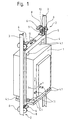
- a cabin 1 is by means of Roller guides 2 guided on rails 3, which are not in one shown shaft are attached.
- the cabin 1 is for passive vibration damping elastic in a cabin frame 4 stored. Rubber springs 4.1 are used, which are relatively stiff be designed to make the occurrence of low frequency Suppress torsional vibrations around the y-axis.
- the Roller guides 2 are on the bottom and top of the side Cabin frame 4 attached. They consist of a stand 5, Actuators 6 and guide elements in the form of two lateral rollers 8 and a middle, rotated by 90 ° to it arranged roller 9.
- Two Position sensors 10 per roller guide 2 each measure the Distance between cabin 1 and rail 3.
- At least three or five Inertia sensors 11 measure those across the cabin 1 occurring vibrations or accelerations.
- the Inertia sensors 11 are preferably in the axis of gravity of the Cabin frame 4 and in pairs far apart arranged to also detect rotations about the z axis can. In addition, wind and rope forces generated vibrations well recorded.
- the data from the Roller guides 2 By processing the measured values, the data from the Roller guides 2 arranged actuators 6, which simultaneous to the vibrations occurring and opposite work towards the direction of the vibrations. So that becomes a Damping of the vibrations acting on the cabin 1 achieved. Vibrations are reduced so that they are on the cabin 1 is no longer in a manner noticeable to the passenger impact.
- Each roller guide 2 is equipped with two actuators 6 equipped. This allows five degrees of freedom or axes of the Cabin 1 can be regulated: displacement in x and y direction, as well as rotation around the x, y and z axes.
- the linear motor 7 is based on the principle of the moving magnet. It consists of one sheeted and provided with turns 15 stator 16 and a movable motor part 17 designed as a magnet. A magnet 18 is attached to the movable motor part 17. Advantages of the linear motor 7 are its simple controllability, as well as light weight and small moving masses and one great dynamic and static power with small Power consumption.
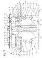
- roller guide 2 according to the device according to the invention.
- the stand 5 is by means of Fasteners 19 attached to the cabin frame 4.
- Each Roller guide 2 is equipped with two actuators 6 which are each provided with a linear motor 7. One shifts the middle roller 9, the other linear motor 7 the two lateral rollers 8.
- the rollers 8, 9 are by means of axle bolts 20 attached to roller levers 21.
- the roller lever 21 of the Both side rollers 8 are connected via a pull rod 22 connected with each other.
- the roller lever 21 by means Axle pin 23 articulated and low-friction with the stand 5 or the roller lever 21 of the two side rollers 8 by means of Axle pin 24 articulated and low friction with the tie rod 22 connected.
- the pressure springs 26 are each fixed to the outer end 27 of the guide rods 25.
- the guide rods 25 run through a bushing 28 in the roller levers 21, so that the pressure springs 26 on the Outer sides 29 of the roller levers 21 rest and the rollers 8, 9 press against the guide rail 3.
- a mounting plate 30 is by means of fasteners 31 attached to the stand 5 like screws.
- the stators 16 of the Actuators 6 are attached to the fastening elements 32 Screwed mounting plate 30.
- the movable motor part 17th is by means of screws 33 on the roller lever 21 and thus with the Rollers 8, 9 connected. So that the air gap 34 of the Linear motor 7 is preserved, is still a lateral one Guided tour required. This consists of ball-bearing Rolls 35 and is almost frictionless.
- Two brackets 36 enable the mounting of the ball-bearing rollers 35 and form the lateral boundaries of the movable motor part 17. Low-friction storage is necessary to ensure that the Actuator 6 to be able to precisely control the force to be generated.
- the length of the stator 16 of the linear motor 7 determines starting from a middle position 37, the maximum possible inner and outer end positions. The path is limited by elastic stops 38 and 39.
- One variant consists of the movable motor part 17 to connect to the roller lever 21 via a pull-push link.
- the movable motor part 17 is then stored regardless of roller lever 21.
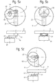
- Fig.5a, 5b and 5c show variants instead of Linear motor 7 to use a rotary drive 43.
- This Drive has a swivel angle of approx. 90 degrees and drives the roller lever 21 with a crank 44 and a pull-push member 45 (Fig.5a) or a flexible traction means 46 (Fig.5b) or with a cam plate 47 (Fig.5c).
- FIG. 6a and 6b show an elevator car 1 with actuators and sensors in the x k direction and in the y k direction according to the inventive device. To simplify the illustration, the x k and y k directions are each shown separately.
- the system model describes the dynamics of the elevator system in all degrees of freedom mentioned above. This model also takes into account all relevant structural resonances that because of the elasticity between the different masses and arise within the cabin frame 4.
- a controller is used which all degrees of freedom described by the model treated at the same time.
- the methods robust multi-size control (multi-input Multi-Output or MIMO Robust Design).
- MIMO Robust Design multi-size control
- These methods use the existing system model to create a to design observer-based controllers.
- the observer is a dynamic part of the controller and has the task based on the existing measurements (e.g. accelerations different measuring points), all not directly measurable Movement states (e.g. speeds and positions of the different masses) in real time.
- the Regulator for maximum information about the system feature. Based on all states of motion and not only on their measurable part does the controller deliver for everyone Degree of freedom the best answer what the quality of Regulation increased significantly.
- the controller does not excite any of these resonances.
- the model-based control provides the necessary System stability. This would not be the case if the System dynamics in the controller design would not be taken into account.
- the robust controller is designed so that it only works in one certain frequency range takes effect so that it is on unwanted frequency-dependent system dynamics and interference not reacted. This is done without additional filters to have to connect the controller.
- the first goal of the regulator is to suppress the Cabin vibrations in the high frequency range (between 0.9 and 15 Hz) without the regulated elevator outside this Range is worse than the unregulated.
- the controller must ensure that the setting of the Cabin frame 4 with respect to the two guide rails 3 so it is regulated that there is a sufficient damping path at each Roll 8, 9 there. This is particularly important if the cabin 1 is loaded asymmetrically.
- For the first regulatory purpose should be an acceleration or a Speed feedback with inertial sensors 11 are sufficient, with a for the second regulation goal Position feedback is necessary. If the absolute Position of cabin 1 measured and for control could be returned, the second repatriation would have with the first no conflict.
- the first controller has the Measurements from the inertial sensors 11 alone and therefore for the suppression of vibrations responsible.
- the second controller has the Position measurements alone and is for the leadership games Cabin 1 responsible.
- the setpoints of the forces that the first Regulators required by the actuators 6 become the corresponding sizes of the second controller added.
- the Solution to avoid the conflict between the two Regulator based on the fact that for the skew forces responsible for cabin 1 (a non-symmetrical Loading of the cabin, a large lateral rope force, etc.) change much more slowly than the other sources of interference, which cause the cabin vibrations (mainly Rail unevenness and air disturbances).
- Controller contains no non-linearity.
- a non-linearity makes stability analysis very difficult if it is even possible. Because the two returns are simultaneous the method takes both into account Control loops in the stability analysis.
- the controllers are for the system in the cabin coordinate system designed. With the help of different linear
- the measurements are transformed from the coordinate system each sensor to the car body coordinate system.
- Another transformation from the cabin coordinate system too the actuator coordinate systems is for the output of the Force setpoints required.
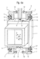
- Fig. 7 shows the controller part of the active system according to the device according to the invention. Since the distances between the Sensors and an analog / digital converter unit 55 relative are long, the measurement signals must be current signals and not are transmitted as voltage signals. The position sensors 10 already deliver their output signals as current. On the other hand the inertial sensors 11 deliver their outputs in the form of Voltage signals. In this case, a voltage / current converter 51 for the output of each inertial sensor 11 necessary. Since the analog / digital converter 55 only Can sense voltage signals becomes an analog Signal processing unit 56 on the part of real-time computer 57 used, which has a channel for each measurement signal. On Channel consists of a current / voltage converter 58, one Anti-aliasing low-pass filter 59, which is used for scanning is necessary, and an ordinary voltage gain 60 to adjust the signal range.
- the core of the real-time computer 57 is the digital one Signal processor 61, which for all mathematical Calculations is responsible. To make the necessary measurements Being able to capture from the hardware becomes a multi-channel Analog / digital converter unit 55 used. For output the force setpoints for the linear motors 7 become one multi-channel digital / analog converter unit 63 used.
- An EEPROM 64 is the entire controller algorithm with all required programs are saved. This program will during commissioning of the active system by one Host computer 65 delivered and to the cabin to be controlled 1 customized. After commissioning, the host computer 65 uncoupled, the one stored on the EEPROM 64 The program stays there until the next calibration is modified or replaced by the host computer 65.
- a RAM 66 is used by the digital signal processor 61 as a memory for the Intermediate values of the calculations used.
- Figure 8 shows the block diagram for the whole system according to the device according to the invention.
- the real-time computer 57 is programmed in this application to use the Controller algorithm with a certain frequency in real time calculated.
- the execution of all linear transformations as well as the The controller algorithm is calculated by the digital Signal processor 61 performed every sampling period.
Landscapes
- Cage And Drive Apparatuses For Elevators (AREA)
- Lift-Guide Devices, And Elevator Ropes And Cables (AREA)
- Types And Forms Of Lifts (AREA)
- Elevator Control (AREA)
- Vibration Prevention Devices (AREA)
Abstract
Description
Die Erfindung betrifft eine Einrichtung und ein Verfahren zur Schwingungsdämpfung an einer an Schienen geführten Aufzugkabine, die zwischen zwei Endstellungen bewegbar mit ihr verbundene Führungselemente aufweist, wobei quer zur Fahrtrichtung auftretende Schwingungen von mehreren an der Kabine angebrachten Trägheitssensoren gemessen und zur Regelung mindestens eines zwischen Kabine und Führungselementen angeordneten Aktuators verwendet werden, der zu den auftretenden Schwingungen und entgegengesetzt zur Richtung der Schwingungen arbeitet.The invention relates to a device and a method for Vibration damping on a guided on rails Elevator car that can be moved between two end positions you have connected guide elements, transverse to Vibrations of several at the direction of travel Attached inertial sensors measured and to the Regulation of at least one between cabin and Guide elements arranged actuator are used which to the vibrations occurring and opposite to Direction of the vibrations works.
Querschwingungen wirken aufgrund von Unebenheiten in den Führungsschienen, sowie durch den Fahrtwind, infolge von seitlichen Zugkräften, die durch die Zugseile übertragen werden oder bei Lageveränderungen der Last während der Fahrt auf die Kabine ein. Aus der US-PS 5,027,925 ist ein Verfahren zur Dämpfung von solchen Schwingungen bei einer Aufzugkabine oder bei einem Teil davon bekannt; nach Ermittlung der unerwünschten Querbeschleunigungen werden hier von einem Vibrationsdämpfer, der zwischen Kabine und Rahmen angeordnet ist, entsprechende Gegenkräfte auf die Kabine ausgeübt. Dieses Verfahren erfordert aber eine aufwendige schwimmende Lagerung der Kabine in einem Kabinenrahmen, was neben dem hohen apparativen Aufwand einen sehr hohen zusätzlichen Platzbedarf mit sich bringt. Ausserdem wirkt die Kraft auf den Rahmen, was bei tiefen Frequenzen ein ruckartiges Hin- und Herschlagen desselben zwischen den Führungen bewirken kann. Ein solches System ist regelungstechnisch kaum beherrschbar. Cross vibrations act due to unevenness in the Guide rails, as well as by the headwind, as a result of lateral tensile forces transmitted through the pull cables or when the load changes position while driving on the cabin. A method is known from US Pat. No. 5,027,925 to dampen such vibrations in an elevator car or known in part of it; after determining the undesirable lateral accelerations are caused by one Vibration damper arranged between the cabin and frame appropriate counterforce is exerted on the cabin. However, this process requires an expensive floating Storage of the cabin in a cabin frame, what next to that high equipment expenditure a very high additional Requires space. The force also acts the frame, which is a jerky and striking the same between the guides can. Such a system is hardly a control technology manageable.
Demgegenüber liegt der Erfindung die Aufgabe zugrunde, die
Einrichtung zur Schwingungsdämpfung und das Verfahren zu
vereinfachen und jederzeit eine befriedigende Dämpfung der
verschiedenen auf die Kabine einwirkenden Schwingungen zu
erzielen. Diese Aufgabe wird durch die im Kennzeichen der
Ansprüche 1, 6 und 8 angegebene Lehre gelöst.In contrast, the invention is based on the object
Vibration damping device and method
simplify and at any time a satisfactory damping of the
various vibrations acting on the cabin
achieve. This task is carried out by the
Besonders vorteilhaft ist die Verwendung je eines Linearmotors pro Aktuator, weil diese Motoren grosse dynamische und statische Kräfte erzeugen können und einen geringen Energieverbrauch haben. Zudem weisen sie geringes Gewicht und geringe bewegte Massen auf und sind relativ einfach zu regeln. Mit der Erfindung werden die auf die Führungselemente ausgeübten Querbeschleunigungen und direkt auf die Kabine wirkende Querkräfte soweit reduziert, dass sie in der Kabine nicht mehr spürbar sind. Die Einrichtung zur Schwingungsdämpfung bleibt auch bei asymmetrischer Beanspruchung funktionstüchtig; sie stellt sich bei Schieflage der Kabine gegenüber den Führungsschienen selbsttätig nach, so dass nach beiden Seiten ein ausreichender Dämpfungsweg zur Verfügung steht.The use of one linear motor each is particularly advantageous per actuator because these motors are large dynamic and can generate static forces and a low Have energy consumption. They also have low weight and low moving masses and are relatively easy to regulate. With the invention on the guide elements exerted lateral accelerations and directly onto the cabin acting transverse forces reduced so far that they are in the cabin are no longer noticeable. The facility for Vibration damping also remains asymmetrical Functional load; she contributes The cabin is inclined to the guide rails automatically after, so that on both sides a sufficient damping path is available.
Der apparative Aufwand zur Durchführung des Verfahrens ist gering und die schnell bewegten Massen sind sehr klein. Dies wird auch dadurch erreicht, dass alle Messsignale einer gemeinsamen Regelung zugeführt werden und diese pro Führungselement nur auf einen einzigen Aktuator wirkt. Ausserdem können durch Anpassung des Frequenzgangs des Reglers Strukturresonanzen unterdrückt werden.The equipment required to carry out the method is low and the fast moving masses are very small. This is also achieved in that all measurement signals of one common rules are supplied and these pro Guide element only acts on a single actuator. In addition, by adjusting the frequency response of the Controller resonances can be suppressed.
Durch die in den abhängigen Ansprüchen aufgeführten Massnahmen sind vorteilhafte Weiterbildungen und Verbesserungen der Erfindung möglich.By those listed in the dependent claims Measures are advantageous training and Improvements of the invention possible.
Vorteilhaft ist insbesondere die Positionsrückführung zur Rückstellung der Führungselemente in die Mittelposition, wobei die Positionsrückführung nur im tiefen Frequenzbereich aktiv ist.The position feedback for is particularly advantageous Return of the guide elements to the middle position, the position feedback only in the low frequency range is active.
Im folgenden wird die Erfindung anhand eines in der Zeichnung dargestellten Ausführungsbeispieles näher erläutert. Es zeigen:
- Fig.1
- eine schematische Darstellung einer an Schienen geführten Aufzugskabine,
- Fig.2
- einen als Linearmotor ausgebildeten Aktuator,
- Fig.3
- eine Frontansicht einer Rollenführung,
- Fig.4
- eine Seitenansicht einer Rollenführung,
- Fig.5a,b,c
- drei Varianten eines Drehantriebs für den Aktuator,
- Fig.6a
- schematisch eine Aufzugskabine mit Aktuatoren und Sensoren in xk-Richtung,
- Fig.6b
- schematisch eine Aufzugskabine mit Aktuatoren und Sensoren in yk-Richtung,
- Fig.7
- den Reglerteil des aktiven Systems, und
- Fig.8
- das Blockdiagramm für das ganze System.
- Fig. 1
- 1 shows a schematic representation of an elevator car guided on rails,
- Fig. 2
- an actuator designed as a linear motor,
- Fig. 3
- a front view of a roller guide,
- Fig. 4
- a side view of a roller guide,
- Fig.5a, b, c
- three variants of a rotary drive for the actuator,
- Fig.6a
- schematically an elevator car with actuators and sensors in the x k direction,
- Fig. 6b
- schematically an elevator car with actuators and sensors in the y k direction,
- Fig. 7
- the controller part of the active system, and
- Fig. 8
- the block diagram for the whole system.
Fig.1 zeigt eine schematische Darstellung der erfindungsgemässen
Einrichtung. Eine Kabine 1 ist mittels
Rollenführungen 2 an Schienen 3 geführt, die in einem nicht
gezeigten Schacht angebracht sind. Die Kabine 1 ist zur
passiven Schwingungsdämpfung elastisch in einem Kabinenrahmen
4 gelagert. Dazu dienen Gummifedern 4.1, die relativ steif
ausgelegt werden, um das Auftreten niederfrequenter
Drehschwingungen um die y-Achse zu unterdrücken. Die
Rollenführungen 2 sind seitlich unten und oben an dem
Kabinenrahmen 4 angebracht. Sie bestehen aus einem Ständer 5,
Aktuatoren 6 und aus Führungselementen in Form von je zwei
seitlichen Rollen 8 und einer mittleren, um 90° dazu verdreht
angeordneten Rolle 9.1 shows a schematic representation of the invention
Facility. A
Unebenheiten in den Schienen 3, seitliche durch die Zugseile
verursachte Zugkräfte oder Lageveränderungen der Last während
der Fahrt bewirken Schwingungen des Kabinenrahmens 4 und der
Kabine 1 und beeinträchtigen somit den Fahrkomfort. Solche
Schwingungen der Kabine 1 sollen reduziert werden. Zwei
Positionssensoren 10 pro Rollenführung 2 messen jeweils den
Abstand der Kabine 1 zur Schiene 3. Mindestens drei oder fünf
Trägheitssensoren 11 messen die quer zur Kabine 1
auftretenden Schwingungen oder Beschleunigungen. Die
Trägheitssensoren 11 sind vorzugsweise in der Schwerachse des
Kabinenrahmens 4 und paarweise weit voneinander entfernt
angeordnet, um auch Drehungen um die z-Achse detektieren zu
können. Ausserdem werden dadurch von Wind- und Seilkräften
erzeugte Erschütterungen gut erfasst.Unevenness in the
Durch Verarbeiten der gemessenen Werte werden die an den
Rollenführungen 2 angeordneten Aktuatoren 6 geregelt, welche
simultan zu den auftretenden Schwingungen und entgegengesetzt
zur Richtung der Schwingungen arbeiten. Damit wird eine
Dämpfung der auf die Kabine 1 einwirkenden Schwingungen
erzielt. Schwingungen werden so reduziert, dass sie sich auf
die Kabine 1 nicht mehr in für den Fahrgast spürbarer Weise
auswirken. Jede Rollenführung 2 wird mit zwei Aktuatoren 6
ausgerüstet. Damit können fünf Freiheitsgrade oder Achsen der
Kabine 1 geregelt werden: Verschiebung in x- und y-Richtung,
sowie Verdrehung um die x-, y- und z-Achse.By processing the measured values, the data from the
Roller guides 2 arranged
Es besteht auch die Möglichkeit, nur die unteren beiden
Rollenführungen 2 mit je zwei Aktuatoren 6 auszurüsten. Damit
können die drei Freiheitsgrade einer Ebene oder drei Achsen
geregelt werden: Verschiebung in x- und in y-Richtung, sowie
Verdrehung um die z-Achse gemäss dem Koordinatensystem in
Fig.1.There is also the option of just the bottom two
Equip roller guides 2 with two
Fig.2 zeigt einen Linearmotor 7 eines Aktuators 6 nach der
erfindungsgemässen Einrichtung. Der Linearmotor 7 beruht auf
dem Prinzip des bewegten Magneten. Er besteht aus einem
geblechten und mit Windungen 15 versehenen Stator 16 und
einem als Magneten ausgebildeten, beweglichen Motorteil 17.
Am beweglichen Motorteil 17 ist ein Magnet 18 angebracht.
Vorteile des Linearmotors 7 sind seine einfache Regelbarkeit,
sowie geringes Gewicht und geringe bewegte Massen und eine
grosse dynamische und statische Kraft bei kleinem
Energieverbrauch.2 shows a
Fig.3 und Fig.4 zeigen eine Rollenführung 2 nach der
erfindungsgemässen Einrichtung. Der Ständer 5 ist mittels
Befestigungselementen 19 am Kabinenrahmen 4 befestigt. Jede
Rollenführung 2 ist mit zwei Aktuatoren 6 ausgerüstet, die
mit je einem Linearmotor 7 versehen sind. Einer verschiebt
die mittlere Rolle 9, der andere Linearmotor 7 die beiden
seitlichen Rollen 8. Die Rollen 8, 9 sind mittels Achsbolzen
20 an Rollenhebeln 21 befestigt. Die Rollenhebel 21 der
beiden seitlichen Rollen 8 werden über eine Zugstange 22
miteinander verbunden. Zum Übertragen der von den Aktuatoren
6 ausgehenden Bewegungen werden die Rollenhebel 21 mittels
Achsbolzen 23 gelenkig und reibungsarm mit dem Ständer 5 bzw.
die Rollenhebel 21 der beiden seitlichen Rollen 8 mittels
Achsbolzen 24 gelenkig und reibungsarm mit der Zugstange 22
verbunden. An den Ständern 5 sind Führungsstangen 25 mit
Andruckfedern 26 angebracht. Die Andruckfedern 26 sind
jeweils am äusseren Ende 27 der Führungsstangen 25 fixiert.
Die Führungsstangen 25 verlaufen durch eine Durchführung 28
in den Rollenhebeln 21, so dass die Andruckfedern 26 auf den
Aussenseiten 29 der Rollenhebel 21 aufliegen und die Rollen
8, 9 an die Führungsschiene 3 pressen. 3 and 4 show a
Eine Befestigungsplatte 30 ist mittels Befestigungselementen
31 wie Schrauben am Ständer 5 angebracht. Die Statoren 16 der
Aktuatoren 6 werden mit Befestigungselementen 32 an die
Befestigungsplatte 30 geschraubt. Der bewegliche Motorteil 17
ist mittels Schrauben 33 am Rollenhebel 21 und somit mit den
Rollen 8, 9 verbunden. Damit der Luftspalt 34 des
Linearmotors 7 erhalten bleibt, ist noch eine seitliche
Führung erforderlich. Diese besteht aus kugelgelagerten
Rollen 35 und ist nahezu reibungsfrei. Zwei Bügel 36
ermöglichen die Montage der kugelgelagerten Rollen 35 und
bilden die seitlichen Begrenzungen des beweglichen Motorteils
17. Eine reibungsarme Lagerung ist notwendig, um die vom
Aktuator 6 zu erzeugende Kraft genau kontrollieren zu können.
Die Länge des Stators 16 des Linearmotors 7 bestimmt
ausgehend von einer Mittelstellung 37 die maximal möglichen
inneren und äusseren Endstellungen. Die Wegbegrenzung erfolgt
durch elastische Anschläge 38 und 39.A mounting
Eine Variante besteht darin, den beweglichen Motorteil 17
über ein Zug-Druck-Glied mit dem Rollenhebel 21 zu verbinden.
Die Lagerung des beweglichen Motorteils 17 erfolgt dann
unabhängig vom Rollenhebel 21.One variant consists of the
Durch die parallele Schaltung der Andruckfeder 26 mit dem
Aktuator 6 bleibt die Rollenführung 2 auch im Falle eines
teilweisen oder vollständigen Ausfalls der aktiven
Schwingungsdämpfung funktionstüchtig, da die Andruckfedern 26
unabhängig vom Aktuator 6 die Rollen 8, 9 an die
Führungsschiene 3 pressen.Through the parallel connection of the
Die Fig.5a, 5b und 5c zeigen Varianten, anstelle des
Linearmotors 7 einen Drehantrieb 43 zu verwenden. Dieser
Antrieb weist einen Schwenkwinkel von ca. 90 Grad auf und
treibt den Rollenhebel 21 mit einer Kurbel 44 und einem Zug-Druck-Glied
45 (Fig.5a) oder einem flexiblen Zugmittel 46
(Fig.5b) oder mit einer Kurvenscheibe 47 (Fig.5c) an. The Fig.5a, 5b and 5c show variants instead of
Fig.6a und 6b zeigen eine Aufzugskabine 1 mit Aktuatoren und
Sensoren in xk-Richtung bzw. in yk-Richtung nach der
erfindungsgemässen Einrichtung. Zur Vereinfachung der
Darstellung sind die xk- und die yk-Richtung jeweils separat
dargestellt.6a and 6b show an
Die Regelung zur Unterdrückung der Kabinenschwingungen und
zur Korrektur der Einstellung der Kabine 1 bezüglich der zwei
Führungsschienen 3 basiert auf einem dynamischen Modell des
Systems. Dieses Modell ist eine mathematische Beschreibung,
die sämtliche vorhandenen praktischen und theoretischen
Erfahrungen mit dem System zusammenfasst. Die Kabinenschwingungen,
die von dieser Einrichtung zu dämpfen sind,
treten in den folgenden Freiheitsgraden auf:
Das Systemmodell beschreibt die Dynamik des Aufzugssystems in
allen oben erwähnten Freiheitsgraden. Dieses Modell
berücksichtigt auch alle relevanten Strukturresonanzen, die
wegen den Elastizitäten zwischen den verschiedenen Massen
sowie innerhalb des Kabinenrahmens 4 entstehen.The system model describes the dynamics of the elevator system in
all degrees of freedom mentioned above. This model
also takes into account all relevant structural resonances that
because of the elasticity between the different masses
and arise within the
Basierend auf dem Systemmodell wird ein Regler verwendet, welcher sämtliche vom Modell beschriebenen Freiheitsgrade gleichzeitig behandelt. Für diesen Zweck werden die Methoden der robusten Mehrgrössenregelung eingesetzt (Multi-Input Multi-Output oder MIMO Robust Design). Diese Methoden benutzen das vorhandene Systemmodell, um einen beobachterbasierten Regler zu entwerfen. Der Beobachter ist ein dynamischer Teil des Reglers und hat die Aufgabe, aufgrund der vorhandenen Messungen (z.B. Beschleunigungen an verschiedenen Messpunkten), sämtliche nicht direkt messbaren Bewegungszustände (z.B. Geschwindigkeiten und Positionen der verschiedenen Massen) in Echtzeit zu schätzen. Somit wird der Regler über ein Maximum an Informationen über das System verfügen. Basierend auf allen Bewegungszuständen und nicht nur auf deren messbaren Teil, liefert der Regler für jeden Freiheitsgrad die beste Antwort, was die Qualität der Regelung wesentlich erhöht. Da das Modell und der darauf basierende Beobachter alle relevanten Strukturresonanzen berücksichtigt, regt der Regler keine dieser Resonanzen an. Die modellbasierte Regelung sorgt für die notwendige Stabilität des Systems. Dies wäre nicht der Fall, wenn die Systemdynamik im Reglerentwurf nicht berücksichtigt wäre.Based on the system model, a controller is used which all degrees of freedom described by the model treated at the same time. For this purpose, the methods robust multi-size control (multi-input Multi-Output or MIMO Robust Design). These methods use the existing system model to create a to design observer-based controllers. The observer is a dynamic part of the controller and has the task based on the existing measurements (e.g. accelerations different measuring points), all not directly measurable Movement states (e.g. speeds and positions of the different masses) in real time. Thus the Regulator for maximum information about the system feature. Based on all states of motion and not only on their measurable part does the controller deliver for everyone Degree of freedom the best answer what the quality of Regulation increased significantly. Because the model and the one on it based observers all relevant structure resonances is taken into account, the controller does not excite any of these resonances. The model-based control provides the necessary System stability. This would not be the case if the System dynamics in the controller design would not be taken into account.
Der robuste Regler wird so entworfen, dass er nur in einem bestimmten Frequenzbereich wirksam wird, damit er auf unerwünschte frequenzabhängige Systemdynamiken und Störungen nicht reagiert. Das wird gemacht, ohne zusätzliche Filter an den Regler anschliessen zu müssen.The robust controller is designed so that it only works in one certain frequency range takes effect so that it is on unwanted frequency-dependent system dynamics and interference not reacted. This is done without additional filters to have to connect the controller.
Zusätzliche Filter können die Wirksamkeit des Reglers beschränken und leicht zu Instabilitäten führen. Sie erhöhen auch den Rechenaufwand des Regelalgorithmus wesentlich. Ein weiterer Vorteil der robusten Entwurfsmethode ist die Berücksichtigung des Modellfehlers während des Entwurfs. Das wird gemacht, indem die Ungenauigkeiten des Modells als frequenzabhängige Grössen quantifiziert und im Reglerentwurf mitberücksichtigt werden. Somit weist der resultierende Regler genügend Robustheit gegen allfällige Störungen und Modellierungsfehler auf.Additional filters can affect the effectiveness of the regulator restrict and easily lead to instabilities. You raise also the computing effort of the control algorithm is essential. On Another advantage of the robust design method is that Consideration of the model error during the design. The is made by using the inaccuracies of the model as frequency-dependent quantities quantified and in the controller design be taken into account. Thus, the resulting one Sufficient robustness against any malfunctions and Modeling errors.
Das erste Ziel des Reglers ist die Unterdrückung der
Kabinenschwingungen im hohen Frequenzbereich ( zwischen 0.9
und 15 Hz), ohne dass der geregelte Aufzug ausserhalb dieses
Bereiches schlechter als der ungeregelte wird. Andererseits
muss der Regler dafür sorgen, dass die Einstellung des
Kabinenrahmens 4 bezüglich der zwei Führungsschienen 3 so
geregelt wird, dass es einen genügenden Dämpfungsweg an jeder
Rolle 8, 9 gibt. Das ist besonders wichtig, wenn die Kabine 1
asymmetrisch beladen wird. Für den ersten Regelungszweck
sollte eine Beschleunigungs- oder eine
Geschwindigkeitsrückführung mit Trägheitssensoren 11
ausreichen, wobei für das zweite Regelungsziel ein
Positionsrückführung notwendig wird. Falls die absolute
Position der Kabine 1 gemessen und für die Regelung
zurückgeführt werden könnte, hätte die zweite Rückführung mit
der ersten keinen Konflikt. Da aber nur Messungen der
relativen Positionen zwischen den Rollen 9 und dem
Kabinenrahmen 4 zur Verfügung stehen, kann die absolute
Position der Kabine 1 nicht gemessen werden, sondern nur die
Lage des Kabinenrahmens 4 relativ zu den Führungsschienen 3.
Die Positionsrückführung soll die Spiele zwischen Rahmen 4
und Rollenhebel 21 konstant halten, was nichts anderes ist
als den Schienenunebenheiten zu folgen. Deshalb haben die
zwei Rückführungen zwei widersprüchliche Ziele. Um den
Konflikt zwischen Beschleunigungs- (oder Geschwindigkeits-)
und Positionsrückführung zu vermeiden, wird folgende
Strategie verfolgt:The first goal of the regulator is to suppress the
Cabin vibrations in the high frequency range (between 0.9
and 15 Hz) without the regulated elevator outside this
Range is worse than the unregulated. On the other hand
the controller must ensure that the setting of the
Es werden zwei Regler zur Erzeugung eines gemeinsamen
Ausgangssignals verwendet. Der erste Regler verfügt über die
Messungen aus den Trägheitssensoren 11 alleine und ist
deswegen für die Unterdrückung der Schwingungen
verantwortlich. Der zweite Regler verfügt über die
Positionsmessungen alleine und ist für die Führungsspiele der
Kabine 1 zuständig. Die Sollwerte der Kräfte, die der erste
Regler von den Aktuatoren 6 verlangt, werden zu den
entsprechenden Grössen des zweiten Reglers addiert. Die
Lösung zum Vermeiden des Konflikts zwischen den beiden
Reglern basiert auf dem Umstand, dass die für die Schieflage
der Kabine 1 verantwortlichen Kräfte (eine nicht symmetrische
Beladung der Kabine, eine grosse seitliche Seilkraft, usw.)
sich wesentlich langsamer ändern als die anderen Störquellen,
welche die Kabinenschwingungen verursachen (hauptsächlich
Schienenunebenheiten und Luftstörkräfte). Deswegen wird die
im tiefen Frequenzbereich arbeitende Positionsregelung,
welche für die Unterdrückung der Schwingungen eher schädlich
ist, auf 0 bis 0.7 Hz begrenzt. Damit ist kein nachteiliger
Einfluss auf die Unterdrückung der Schwingungen vorhanden,
weil diese erst ab 0.9 Hz funktioniert. Die Rückführung der
Signale aus den Trägheitssensoren 11 darf im Frequenzbereich
unter 0.9 Hz nicht wirksam sein, damit der Sensornullfehler
und, im Falle eines Beschleunigungssensors, der gemessene
Teil der Gravitation, der wegen der Kippbewegung nicht
konstant ist, keinen Einfluss auf die Positionsregelung hat.
Damit wird auch die Gefahr einer Übersteuerung der Aktuatoren
6 vermieden. Für diesen Zweck wird die Begrenzung der
Bandbreite jeder Rückführungsschlaufe mittels des robusten
Entwurfsverfahrens besonders wichtig.There are two controllers to create a common one
Output signal used. The first controller has the
Measurements from the
Ein weiterer Vorteil dieser Lösung liegt darin, dass der Regler keine Nichtlinearität enthält. Eine Nichtlinearität macht die Stabilitätsanalyse sehr schwierig, wenn sie überhaupt möglich ist. Da die zwei Rückführungen gleichzeitig entworfen werden, berücksichtigt das Verfahren beide Regelschlaufen in der Stabilitätsanalyse.Another advantage of this solution is that the Controller contains no non-linearity. A non-linearity makes stability analysis very difficult if it is even possible. Because the two returns are simultaneous the method takes both into account Control loops in the stability analysis.
Besonders vorteilhaft für eine effiziente Regelung ist die
Montage der Trägheitssensoren 11 auf dem Kabinenrahmen 4
anstatt auf dem Kabinenkörper 1 oder auf den Rollenführungen
2. Würden die Sensoren auf dem Kabinenkörper 1 montiert, so
würden die Messungen erhebliche Phasenverluste aufweisen, die
auf die elastische Aufhängung der Kabine 1 zurückgehen. An
den Rollenführungen treten weit höhere Schwingungsamplituden
auf und der Schwerkrafteinfluss müsste kompensiert werden.This is particularly advantageous for efficient control
Mounting the
Die Regler werden für das System im Kabinenkoordinatensystem ausgelegt. Mit Hilfe von verschiedenen linearen Transformationen werden die Messungen vom Koordinatensystem jedes Sensors zum Kabinenkörperkoordinatensystem abgebildet. Eine andere Transformation vom Kabinenkoordinatensystem zu den Aktuatorkoordinatensystemen ist für die Ausgabe der Kraftsollwerte notwendig.The controllers are for the system in the cabin coordinate system designed. With the help of different linear The measurements are transformed from the coordinate system each sensor to the car body coordinate system. Another transformation from the cabin coordinate system too the actuator coordinate systems is for the output of the Force setpoints required.
Das aktive System zur Dämpfung der Kabinenschwingungen und zur Einstellkorrektur der Kabine 1 in fünf Freiheitsgraden (xk, ϕky, yk, ϕkx, ϕkz) besteht aus den folgenden Elementen:
Acht Linearmotoren 7oder Drehantriebe 43- Acht
Verstärker und Kraftregler 50 für dieLinearmotoren 7oder Drehantriebe 43 - Fünf Trägheitssensoren 11 (Beschleunigungs- oder Geschwindigkeitsaufnehmer)
- Fünf Spannungs/
Stromwandler 51 für die Ausgänge der Trägheitssensoren 11 Acht Positionssensoren 10
- Eight
linear motors 7 or rotary drives 43 - Eight amplifiers and
force controllers 50 for thelinear motors 7 or rotary drives 43 - Five inertial sensors 11 (acceleration or speed sensors)
- Five voltage /
current converters 51 for the outputs of theinertial sensors 11 - Eight
position sensors 10
Im Fall einer kostengünstigeren Version des aktiven Systems
werden nur drei Freiheitsgrade der Kabine geregelt (xk, yk, ϕ
z). Es werden deshalb nur unten Linearmotoren 7 und Sensoren
10, 11 montiert. Der Rechenaufwand wird in diesem Fall
wesentlich geringer, was die Anwendung eines langsamen und
kostengünstigen Echtzeitrechners ermöglicht.In the case of a cheaper version of the active system, only three degrees of freedom of the cabin are regulated (x k , y k , ϕ z ). Therefore,
Fig.7 zeigt den Reglerteil des aktiven Systems nach der
erfindungsgemässen Einrichtung. Da die Abstände zwischen den
Sensoren und einer Analog/Digital-Wandlereinheit 55 relativ
lang sind, müssen die Messsignale als Stromsignale und nicht
als Spannungssignale übertragen werden. Die Positionssensoren
10 liefern ihre Ausgangssignale bereits als Strom. Hingegen
liefern die Trägheitssensoren 11 ihre Ausgänge in Form von
Spannungssignalen. In diesem Fall wird ein Spannung/Strom-Wandler
51 für den Ausgang jedes Trägheitssensors 11
notwendig. Da die Analog/Digital-Wandler 55 nur
Spannungssignale abtasten können, wird eine analoge
Signalverarbeitungseinheit 56 seitens des Echtzeitrechners 57
gebraucht, welche einen Kanal für jedes Messsignal hat. Ein
Kanal besteht aus einem Strom/Spannungs-Wandler 58, einem
Anti-Aliasing-Tiefpassfilter 59, welches für das Abtasten
notwendig ist, und einer gewöhnlichen Spannungsverstärkung 60
zur Anpassung des Signalbereiches.Fig. 7 shows the controller part of the active system according to the
device according to the invention. Since the distances between the
Sensors and an analog /
Der Kern des Echtzeitrechners 57 stellt der digitale
Signalprozessor 61 dar, welcher für sämtliche mathematischen
Berechnungen verantwortlich ist. Um die notwendigen Messungen
aus der Hardware erfassen zu können, wird eine mehrkanalige
Analog/Digital-Wandlereinheit 55 gebraucht. Für die Ausgabe
der Kraftsollwerte zu den Linearmotoren 7 wird eine
mehrkanalige Digital/Analog-Wandlereinheit 63 benutzt. In
einem EEPROM 64 wird der gesamte Regleralgorithmus mit allen
benötigten Programmen abgespeichert. Dieses Programm wird
während der Inbetriebnahme des aktiven Systems von einem
Hostrechner 65 geliefert und an die zu regelnde Kabine 1
angepasst. Nach der Inbetriebnahme wird der Hostrechner 65
abgekoppelt, wobei das auf dem EEPROM 64 abgespeicherte
Programm dort bleibt, bis es während der nächsten Kalibration
vom Hostrechner 65 modifiziert oder ersetzt wird. Ein RAM 66
wird vom digitalen Signalprozessor 61 als Speicher für die
Zwischenwerte der Berechnungen gebraucht. Für die
Kommunikation zwischen dem digitalen Signalprozessor 61 und
allen diesen Komponenten wird ein Datenbus 67 benutzt. An
diesem Datenbus 67 wird auch ein für die Verbindung mit dem
Hostrechner verantwortliches Modul in Form eines
Kommunikationsports 68 angeschlossen.The core of the real-
Die Möglichkeit, die Rechenaufgabe zwischen zwei digitalen
Signalprozessoren 61 aufzuteilen, die an denselben Datenbus
67 angeschlossen sind, ist möglich, falls die Aufgabe von
einem einzigen Signalprozessor 61 nicht genügend schnell
gelöst werden kann.The possibility of doing the arithmetic between two digital
Fig.8 zeigt das Blockdiagramm für das ganze System nach der
erfindungsgemässen Einrichtung. Der Echtzeitrechner 57 wird
in dieser Anwendung so programmiert, dass er den
Regleralgorithmus mit einer bestimmten Frequenz in Echtzeit
durchrechnet.Figure 8 shows the block diagram for the whole system according to the
device according to the invention. The real-
Der Algorithmus besteht aus den folgenden Schritten, die nicht unbedingt in der angegebenen Reihenfolge ausgeführt werden müssen:
- Die Verarbeitung der Messungen aus
den fünf Trägheitssensoren 11auf dem Kabinenrahmen 4 in xk- sowie in yk-Richtung. Die gemessenen Signale werden in Spannungs/Strom-Wandler 51 umgewandelt und durch die analoge Signalverarbeitungseinheit 56 übertragen und von Analog/Digital-Wandlerkanälen 55 abgetastet. - Die oben erwähnten Messungen liegen in den
Koordinatensystemen der Trägheitssensoren 11 vor. Da die Regelung im Kabinenkoordinatensystem geschieht, müssen sie in dieses Koordinatensystem transformiert werden. Zu diesem Zweck benutzt der Algorithmus die lineare Transformation TKT. Die Ausgänge dieser Transformation sind: - Die Translationsbeschleunigung (bzw. die
Translationsgeschwindigkeit) der
Kabine 1 in xk-Richtung (k, bzw. x ˙k).
- Die Drehbeschleunigung (bzw. die Drehgeschwindigkeit) der
Kabine 1 um die yk-Achse (ky, bzw. ϕ ˙ky).
- Die Translationsbeschleunigung (bzw. die Translationsgeschwindigkeit) der Kabine in yk-Richtung (ÿk, bzw. y ˙k).
- Die Drehbeschleunigung (bzw. die Drehgeschwindigkeit) der
Kabine 1 um die xk-Achse ( - Die Drehbeschleunigung (bzw. die Drehgeschwindigkeit) der
Kabine 1 um die zk-Achse (
- The processing of the measurements from the five
inertial sensors 11 on thecabin frame 4 in the x k and y k directions. The measured signals are converted into voltage /current converters 51 and transmitted by the analogsignal processing unit 56 and sampled by analog /digital converter channels 55. - The above-mentioned measurements are in the coordinate systems of the
inertial sensors 11. Since the regulation takes place in the cabin coordinate system, it must be transformed into this coordinate system. For this purpose the algorithm uses the linear transformation T KT . The outputs of this transformation are: - The translation acceleration (or the translation speed) of the
cabin 1 in the x k direction (k , or x ˙ k ). - The rotational acceleration (or the rotational speed) of the
cabin 1 around the y k axis (ky , or ϕ ˙ ky ). - The translation acceleration (or the translation speed) of the cabin in the y k direction (ÿ k , or y ˙ k ).
- The rotational acceleration (or the rotational speed) of the
cabin 1 around the x k axis ( - The rotational acceleration (or the rotational speed) of the
cabin 1 around the z k axis (
Der Sollwert für jede dieser Grössen ist Null. Deshalb werden die fünf Signale von Null subtrahiert, bevor sie dem robusten Mehrgrössenregler I überliefert werden. Dieser Regler I reagiert auf die fünf Signale gleichzeitig nach dem oben beschriebenen Konzept und liefert am Ausgang die folgenden Signale aus:
- Einen Kraftsollwert FT xs in xk-Richtung.
- Einen Drehmomentsollwert MT ys um die yk-Achse.
- Einen Kraftsollwert FT ys in yk-Richtung.
- Einen Drehmomentsollwert MT xs um die xk-Achse.
- Einen Drehmomentsollwert MT zs um die zk-Achse.
- A force setpoint F T xs in the x k direction.
- A torque setpoint M T ys around the y k axis.
- A force setpoint F T ys in the y k direction.
- A torque setpoint M T xs around the x k axis.
- A torque setpoint M T zs around the z k axis.
Anhand einer linearen Transformation TT AK werden die Sollwerte aus dem Regler I in die Aktuatorkoordinatensysteme transformiert.
- Die Messungen
aus den Positionssensoren 10 in xk-Richtung und in yk-Richtung. Die gemessenen Signale werden durch die analoge Signalverarbeitungseinheit 56 übertragen und von Analog/Digital-Wandlerkanälen 55 abgetastet. Da diese Messungen im Positionssensorkoordinatensystem vorliegen, müssen sie ins Kabinenkoordinatensystem transformiert werden. Dafür wird eine lineare Transformation TKP benutzt. Diese Transformation liefert fünf Positionssignale als Ausgang. Um die Positionsfehlersignale zu erhalten, wird jedes dieser Signale von Null subtrahiert. Somit werden zwei translatorische (xE K und yE K) und drei rotatorische Positionsfehlersignale (ϕE Kx, ϕE Xy und ϕE Kz) erhalten. - Auf die fünf Positionsfehler reagiert ein robuster
Mehrgrössenregler II gemäss dem oben erwähnten Konzept und
liefert als Ausgang die folgenden Sollwerte zur Korrektur
der Aufzugseinstellung:
- Den Kraftsollwert FP xs für die Verschiebung in xk-Richtung.
- Den Drehmomentsollwert MP ys für die Drehung um die yk-Achse.
- Den Kraftsollwert FP ys für die Verschiebung in yk-Richtung.
- Den Drehmomentsollwert MP xs für die Drehung um die xk-Achse.
- Den Drehmomentsollwert MP zs für die Drehung um die zK-Achse.
- Anhand der linearen Transformation TP AK werden die
Sollwerte aus dem Regler II in das
Aktuatorkoordinatensystem transformiert. Der Unterschied
zwischen den beiden linearen Transformationen TT AK und TP AK
liegt darin, dass die von der zweiten Transformation
resultierenden Kraftsollwerte der Linearmotoren 6 in xk-Richtung
nur Druckkräfte auf die
Schienen 3 verursachen. Das wird erreicht, indem ein einziger Aktuator in xk-Richtung unten und ein einziger Aktuator in xk-Richtung oben gleichzeitig vom Regler II betätigt werden. Somit wird sichergestellt, dass keine der vierRollen 9 in xk-Richtung den Kontaktmit den Führungsschienen 3 verliert. Im Fall der ersten Transformation ist dies nicht möglich, weil sie wesentlich weniger Kräfte verlangt als die zweite Transformation. - Die entsprechenden Ausgänge aus den zwei Transformationen TT AK und TP AK werden zusammen addiert, um die Kraftsollwerte für jeden der acht Linearmotoren 7 zu berechnen.
- Die Kraftsollwerte werden von den Digital/Analog-
Wandlerkanälen 63 zu analogen Signalen umgewandelt. Die resultierenden Signale treiben die entsprechenden Leistungsverstärker und Kraftregler 50, welche dieStröme der Linearmotoren 7 durch analoge Rückführungen regeln.Die Leistungsverstärker 50 sind pulsbreitenmoduliert.Der Kabinenrahmen 4 wird nun von den resultierenden Kräften so beeinflusst, dass die zwei Regelziele erreicht werden. Sollte der jeweilige Kraftsollwert (bei störungsfreier Fahrt) den Wert Null annehmen, so übt der zugeordnete Aktuator keine Kräfte aus.
- The measurements from the
position sensors 10 in the x k direction and in the y k direction. The measured signals are transmitted by the analogsignal processing unit 56 and sampled by analog /digital converter channels 55. Since these measurements are available in the position sensor coordinate system, they must be transformed into the cabin coordinate system. A linear transformation T KP is used for this. This transformation provides five position signals as an output. To obtain the position error signals, each of these signals is subtracted from zero. Two translatory (x E K and y E K ) and three rotatory position error signals (ϕ E Kx , ϕ E Xy and ϕ E Kz ) are thus obtained. - A robust multi-size controller II reacts to the five position errors in accordance with the concept mentioned above and provides the following setpoints as an output for correcting the elevator setting:
- The force setpoint F P xs for the displacement in the x k direction.
- The torque setpoint M P ys for the rotation around the y k axis.
- The force setpoint F P ys for the displacement in the y k direction.
- The torque setpoint M P xs for the rotation around the x k axis.
- The torque setpoint M P zs for the rotation around the z K axis.
- Using the linear transformation T P AK , the setpoints from the controller II are transformed into the actuator coordinate system. The difference between the two linear transformations T T AK and T P AK is that the force setpoints of the
linear motors 6 resulting from the second transformation in the x k direction only cause pressure forces on therails 3. This is achieved by simultaneously actuating a single actuator in the xk direction at the bottom and a single actuator in the x k direction at the top by controller II. This ensures that none of the fourrollers 9 loses contact with theguide rails 3 in the x k direction. In the case of the first transformation, this is not possible because it requires far less force than the second transformation. - The corresponding outputs from the two transformations T T AK and T P AK are added together in order to calculate the force setpoints for each of the eight
linear motors 7. - The force setpoints are converted by the digital /
analog converter channels 63 to analog signals. The resulting signals drive the corresponding power amplifiers andforce regulators 50, which regulate the currents of thelinear motors 7 by means of analog feedback. Thepower amplifiers 50 are pulse width modulated. Thecabin frame 4 is now influenced by the resulting forces so that the two control goals are achieved. If the respective force setpoint (when driving smoothly) assumes the value zero, the assigned actuator does not exert any forces.
Die Ausführung aller linearen Transformationen sowie die
Berechnung des Regleralgorithmus wird vom digitalen
Signalprozessor 61 in jeder Abtastperiode durchgeführt.The execution of all linear transformations as well as the
The controller algorithm is calculated by the
Claims (10)
- Equipment for the reduction of oscillations of a lift cage (1), which is guided at rails (3) and displays guide elements (21), which are connected with it to be movable between abutments (38, 39), wherein oscillations arising transversely to the direction of travel are measured by inertia sensors (11) mounted at the cage (1) and used for the regulation of at least one actuator (6), which is arranged between the cage (1) and the guide elements (21) and operates simultaneously with the arising oscillations and oppositely to the direction of the oscillations, characterised thereby that the or each actuator (6) is equipped with a respective linear motor (7), wherein the stationary motor part (16) is fastened at the frame of the cage (1) and the movable motor part (17) is fastened at the guide elements (21).
- Equipment according to claim 1, characterised thereby that the movable motor part (17) is a magnet.
- Equipment according to claim 1 or 2, characterised thereby that a roller lever, at which the movable motor part (17) is fastened, serves as guide element (21).
- Equipment according to claim 1 or 2, characterised thereby that a roller lever, which is connected with the movable motor part (17) by way of a tension-compression member, serves as guide element (21).
- Equipment according to one of the claims 1 to 4, characterised thereby that a low-friction guide (35) maintains an air gap (34) between the stationary motor part (16) and the movable motor part (17).
- Equipment for the reduction of oscillations of a lift cage (1), which is guided at rails (3) and displays guide elements (21), which are connected with it to be movable between two abutments (38, 39), wherein oscillations arising transversely to the direction of travel are measured by inertia sensors (11) mounted at the cage (1) and used for the regulation of at least one actuator (6), which is arranged between the cage (1) and the guide elements (21) and operates simultaneously with the arising oscillations and oppositely to the direction of the oscillations, characterised thereby that the actuators (6) are equipped with rotary drives (43), wherein the movable motor part is fastened at the guide elements (21) by way of a crank (44) and a tension-compression member (45).
- Equipment according to the classifying clause of the claim 6, characterised thereby that the actuators (6) are equipped with rotary drives (43), wherein the movable motor part is connected with the guide elements (21) by way of a cam plate (47) or by way of a flexible tension means (46).
- Method according for the reduction of oscillations of a lift cage (1), which is guided at rails (3) and displays guide elements (21), which are connected with it to be movable between two abutments (38, 39), wherein oscillations arising transversely to the direction of travel are measured by inertia sensors (11) mounted at the cage (1) and used for the regulation of at least one actuator (6), which is arranged between the cage (1) and the guide elements (21) and operates simultaneously with the arising oscillations and oppositely to the direction of the oscillations, characterised thereby that the actuators (6) are equipped with regulated linear motors (7) or regulated rotary drives (43), wherein the regulation takes place through the outputs, which are combined into one force target value, of two regulators, a rapid acceleration return movement and a slow position return movement.
- Method according to claim 8, characterised by a return movement to the guide elements (21), which reacts to the measured oscillation travels or their time derivatives in order to minimise the actual oscillations of the cage (1) and characterised thereby that a midposition is defined for the guide elements (21) relative to their end settings (38, 39) and that, in the case of noticeable deviations therefrom, they are guided back slowly into this position by the actuators (6).
- Method according to one of the preceding claims, characterised thereby that the rapid acceleration return movement and the slow position return movement are realised by two regulating loops with a regulator (I) and a regulator (II), which belong to a regulating part implemented as a computing program in a preferably digital signal processor (61).
Applications Claiming Priority (3)
| Application Number | Priority Date | Filing Date | Title |
|---|---|---|---|
| CH694/95 | 1995-03-10 | ||
| CH69495 | 1995-03-10 | ||
| CH69495 | 1995-03-10 |
Publications (2)
| Publication Number | Publication Date |
|---|---|
| EP0731051A1 EP0731051A1 (en) | 1996-09-11 |
| EP0731051B1 true EP0731051B1 (en) | 2001-05-23 |
Family
ID=4192985
Family Applications (1)
| Application Number | Title | Priority Date | Filing Date |
|---|---|---|---|
| EP96103184A Expired - Lifetime EP0731051B1 (en) | 1995-03-10 | 1996-03-01 | Device and method for damping vibrations on an elevator cage |
Country Status (11)
| Country | Link |
|---|---|
| US (1) | US5896949A (en) |
| EP (1) | EP0731051B1 (en) |
| JP (2) | JPH08245117A (en) |
| CN (1) | CN1050580C (en) |
| AT (1) | ATE201380T1 (en) |
| AU (1) | AU702382B2 (en) |
| CA (1) | CA2171376C (en) |
| DE (1) | DE59606928D1 (en) |
| HK (1) | HK1011340A1 (en) |
| MY (1) | MY115725A (en) |
| SG (1) | SG54248A1 (en) |
Families Citing this family (47)
| Publication number | Priority date | Publication date | Assignee | Title |
|---|---|---|---|---|
| DK0831797T3 (en) * | 1995-06-07 | 2007-04-02 | Howard Foundation | Pharmaceutically active carotenoids |
| JP4131764B2 (en) * | 1998-09-01 | 2008-08-13 | 東芝エレベータ株式会社 | Elevator equipment |
| FI981887A (en) * | 1998-09-04 | 2000-03-05 | Kone Corp | An elevator arrangement for setting the output torque of an elevator motor |
| US6216824B1 (en) * | 1998-12-24 | 2001-04-17 | United Technologies Corporation | Semi-active elevator hitch |
| JP4161063B2 (en) | 1999-10-22 | 2008-10-08 | 三菱電機株式会社 | Elevator device and guide device for elevator device |
| US6305502B1 (en) * | 1999-12-21 | 2001-10-23 | Otis Elevator Company | Elevator cab floor acceleration control system |
| US6435314B1 (en) * | 2000-03-24 | 2002-08-20 | Otis Elevator Company | Elevator platform stabilization coupler |
| SG89424A1 (en) * | 2000-10-23 | 2002-06-18 | Inventio Ag | Method and system for compensating vibrations in elevator cars |
| JP4413505B2 (en) * | 2002-03-07 | 2010-02-10 | インベンテイオ・アクテイエンゲゼルシヤフト | Equipment for damping elevator car vibrations |
| JP4107480B2 (en) * | 2002-07-29 | 2008-06-25 | 三菱電機株式会社 | Elevator vibration reduction device |
| SG109535A1 (en) * | 2003-08-14 | 2005-03-30 | Inventio Ag | Electric motor, lift with a cage movable by an electric motor, and lift with a cage and with an electric motor for movement of a guide element relative to the cage |
| EP1507329A1 (en) * | 2003-08-14 | 2005-02-16 | Inventio Ag | Electric motor, lift with a car moved with an electric motor and lift with a car and an electric motor for actuating a guide member relatively to the car |
| US7141946B2 (en) * | 2003-09-15 | 2006-11-28 | Rockwell Automation Technologies, Inc. | Method and apparatus for providing optimal acceleration feedback |
| EP1547956B1 (en) * | 2003-12-22 | 2007-09-05 | Inventio Ag | Device and method for reducing vibration in an elevator cabin |
| EP1547955B1 (en) * | 2003-12-22 | 2006-11-08 | Inventio Ag | Controller supervision for active vibration damping of elevator cars |
| EP1547957A1 (en) * | 2003-12-22 | 2005-06-29 | Inventio Ag | Device for damping the vibration of an elevator cabin |
| EP1547958B1 (en) * | 2003-12-22 | 2007-05-23 | Inventio Ag | Thermal protection of electromagnetic actuators |
| DE602004003117T2 (en) * | 2003-12-22 | 2007-05-10 | Inventio Ag, Hergiswil | Control unit for the active vibration damping of the vibrations of an elevator car |
| MY142882A (en) * | 2003-12-22 | 2011-01-31 | Inventio Ag | Equipment and method for vibration damping of a lift cage |
| SG112944A1 (en) * | 2003-12-22 | 2005-07-28 | Inventio Ag | Equipment for vibration damping of a lift cage |
| SG112941A1 (en) * | 2003-12-22 | 2005-07-28 | Inventio Ag | Thermal protection of electromagnetic actuators |
| MY138827A (en) | 2004-02-02 | 2009-07-31 | Inventio Ag | Method for vibration damping at an elevator car |
| MY192706A (en) * | 2004-12-17 | 2022-09-02 | Inventio Ag | Lift installation with a braking device, and method for braking and holding a lift installation |
| JP4800793B2 (en) * | 2006-02-24 | 2011-10-26 | 三菱電機ビルテクノサービス株式会社 | Elevator control device |
| CN101522553B (en) * | 2006-12-05 | 2012-02-01 | 三菱电机株式会社 | Elevator apparatus |
| JP5009304B2 (en) * | 2006-12-13 | 2012-08-22 | 三菱電機株式会社 | Elevator equipment |
| US9114954B2 (en) * | 2008-05-23 | 2015-08-25 | Thyssenkrupp Elevator Corporation | Active guiding and balance system for an elevator |
| US8768522B2 (en) * | 2012-05-14 | 2014-07-01 | Mitsubishi Electric Research Laboratories, Inc. | System and method for controlling semi-active actuators |
| US9828211B2 (en) | 2012-06-20 | 2017-11-28 | Otis Elevator Company | Actively damping vertical oscillations of an elevator car |
| CN102788661B (en) * | 2012-07-11 | 2014-11-19 | 三洋电梯(珠海)有限公司 | Lift car gravity center tester |
| WO2014057302A1 (en) * | 2012-10-08 | 2014-04-17 | Otis Elevator Company | Low friction sliding guide shoe for elevator |
| WO2014070203A1 (en) * | 2012-11-05 | 2014-05-08 | Otis Elevator Company | Inertial measurement unit assisted elevator position calibration |
| JP6173752B2 (en) * | 2013-04-10 | 2017-08-02 | 株式会社日立製作所 | Elevator with vibration control device |
| JP6295166B2 (en) * | 2014-08-18 | 2018-03-14 | 株式会社日立製作所 | Elevator apparatus and vibration damping mechanism adjusting method thereof |
| CN107108171B (en) * | 2014-12-17 | 2020-05-29 | 因温特奥股份公司 | Vibration damping unit for elevator |
| JP6399404B2 (en) * | 2015-03-20 | 2018-10-03 | フジテック株式会社 | Car roll restraining device and elevator roll restraining method for elevator |
| US20170008736A1 (en) * | 2015-07-09 | 2017-01-12 | Otis Elevator Company | Active vibration damper for a linear propulsion system of a ropeless elevator |
| CN106477431B (en) | 2015-09-01 | 2020-01-21 | 奥的斯电梯公司 | Elevator car cab isolation |
| JP6158381B1 (en) * | 2016-03-09 | 2017-07-05 | 東芝エレベータ株式会社 | Elevator equipment |
| JP2017160005A (en) * | 2016-03-09 | 2017-09-14 | 東芝エレベータ株式会社 | Elevator device |
| JP6591923B2 (en) * | 2016-03-30 | 2019-10-16 | 株式会社日立製作所 | Elevator equipment |
| US10407274B2 (en) | 2016-12-08 | 2019-09-10 | Mitsubishi Electric Research Laboratories, Inc. | System and method for parameter estimation of hybrid sinusoidal FM-polynomial phase signal |
| CN108285081B (en) | 2017-01-10 | 2021-08-03 | 奥的斯电梯公司 | Elevator car stabilizing device, control method thereof and elevator system |
| US10866124B2 (en) | 2017-10-24 | 2020-12-15 | Mitsubishi Electric Research Laboratories, Inc. | Systems and methods for speed estimation of contactless encoder systems |
| CN109095328B (en) * | 2018-09-28 | 2020-07-31 | 山东富士制御电梯有限公司 | Vibration reduction system for horizontal vibration of high-speed elevator car and control method thereof |
| US11795032B2 (en) * | 2018-11-13 | 2023-10-24 | Otis Elevator Company | Monitoring system |
| US11104545B2 (en) | 2018-12-10 | 2021-08-31 | Otis Elevator Company | Elevator safety actuator systems |
Family Cites Families (12)
| Publication number | Priority date | Publication date | Assignee | Title |
|---|---|---|---|---|
| FI884380A (en) * | 1988-09-23 | 1990-03-24 | Kone Oy | FOERFARANDE OCH ANORDNING FOER DAEMPANDET AV VIBRATIONER I EN HISSKORG. |
| JP2728513B2 (en) * | 1989-08-30 | 1998-03-18 | 株式会社日立製作所 | Elevator equipment |
| US5294757A (en) * | 1990-07-18 | 1994-03-15 | Otis Elevator Company | Active vibration control system for an elevator, which reduces horizontal and rotational forces acting on the car |
| US5322144A (en) * | 1990-07-18 | 1994-06-21 | Otis Elevator Company | Active control of elevator platform |
| JP2756208B2 (en) * | 1991-03-13 | 1998-05-25 | オーチス エレベータ カンパニー | Horizontal deviation correction device for elevator cars running vertically |
| DE69211040T2 (en) * | 1991-03-13 | 1996-12-12 | Otis Elevator Co | Elevator rail cross section evaluation and elevator control method |
| CA2072240C (en) * | 1991-07-16 | 1998-05-05 | Clement A. Skalski | Elevator horizontal suspensions and controls |
| US5289902A (en) * | 1991-10-29 | 1994-03-01 | Kabushiki Kaisha Toshiba | Elevator |
| JP2616527B2 (en) * | 1992-01-06 | 1997-06-04 | 株式会社日立製作所 | Elevator device and control method thereof |
| DE69502229T2 (en) * | 1994-03-31 | 1998-08-13 | Otis Elevator Co | Control device for active vibration control |
| US5652414A (en) * | 1994-08-18 | 1997-07-29 | Otis Elevator Company | Elevator active guidance system having a coordinated controller |
| US5535853A (en) * | 1994-11-14 | 1996-07-16 | Otis Elevator Company | Actuator having a two ended actuator rod movable longitudinally and transversely |
-
1996
- 1996-03-01 EP EP96103184A patent/EP0731051B1/en not_active Expired - Lifetime
- 1996-03-01 DE DE59606928T patent/DE59606928D1/en not_active Expired - Lifetime
- 1996-03-01 AT AT96103184T patent/ATE201380T1/en not_active IP Right Cessation
- 1996-03-07 AU AU47919/96A patent/AU702382B2/en not_active Ceased
- 1996-03-08 US US08/613,168 patent/US5896949A/en not_active Expired - Lifetime
- 1996-03-08 SG SG1996006131A patent/SG54248A1/en unknown
- 1996-03-08 JP JP8052073A patent/JPH08245117A/en not_active Withdrawn
- 1996-03-08 CA CA002171376A patent/CA2171376C/en not_active Expired - Fee Related
- 1996-03-08 CN CN96102730A patent/CN1050580C/en not_active Expired - Fee Related
- 1996-03-09 MY MYPI96000878A patent/MY115725A/en unknown
-
1998
- 1998-11-26 HK HK98112337A patent/HK1011340A1/en not_active IP Right Cessation
-
2008
- 2008-08-15 JP JP2008209253A patent/JP4493709B2/en not_active Expired - Lifetime
Also Published As
| Publication number | Publication date |
|---|---|
| JPH08245117A (en) | 1996-09-24 |
| CN1134392A (en) | 1996-10-30 |
| CA2171376A1 (en) | 1996-09-11 |
| EP0731051A1 (en) | 1996-09-11 |
| SG54248A1 (en) | 1998-11-16 |
| MY115725A (en) | 2003-08-30 |
| JP2008297127A (en) | 2008-12-11 |
| CA2171376C (en) | 2006-06-13 |
| AU4791996A (en) | 1996-09-19 |
| HK1011340A1 (en) | 1999-07-09 |
| US5896949A (en) | 1999-04-27 |
| JP4493709B2 (en) | 2010-06-30 |
| DE59606928D1 (en) | 2001-06-28 |
| CN1050580C (en) | 2000-03-22 |
| ATE201380T1 (en) | 2001-06-15 |
| AU702382B2 (en) | 1999-02-18 |
Similar Documents
| Publication | Publication Date | Title |
|---|---|---|
| EP0731051B1 (en) | Device and method for damping vibrations on an elevator cage | |
| DE69512491T2 (en) | Active guidance system of an elevator | |
| DE69224240T2 (en) | Elevator car guide device | |
| DE69230071T2 (en) | Horizontal elevator suspension system with control device | |
| DE69203688T2 (en) | Improved elevator ride quality. | |
| DE3631633C2 (en) | ||
| DE60102335T2 (en) | Suspension device with an electric actuator with a parallel spring | |
| DE112014001217B4 (en) | Method and system for controlling a set of semi-active actuators arranged in an elevator | |
| DE102011052205A9 (en) | Position control system for cross-coupled operation of fly-by-wire control columns | |
| DE102017105129A1 (en) | Method for controlling vibrations of an elevator cable connected to an elevator car | |
| DE69810150T2 (en) | ENGINE SPEED REGULATOR AND METHOD FOR ADJUSTING THE REGULATOR GAIN | |
| DE2219487A1 (en) | Test device for position force cross-coupling control | |
| DE112007003699B4 (en) | Door control device for a lift | |
| EP3424136B1 (en) | Linear motor arrangement for an elevator | |
| EP3672808B1 (en) | Control of printing presses having a plurality of main drive motors | |
| DE69211040T2 (en) | Elevator rail cross section evaluation and elevator control method | |
| EP0557541A1 (en) | Control with feedforward, especially for a rolling stand | |
| DE102014018974A1 (en) | Control device for a machine with a function for reducing synchronization errors | |
| DE2836595A1 (en) | METHOD FOR CONTROLLING THE THICKNESS OF A FLAT PRODUCT DURING ROLLING AND DEVICE FOR CARRYING OUT THE METHOD | |
| DE19961880A1 (en) | Electric drive system for active vibration damping e.g. in sheet or roller printer, has acceleration sensors on functional parts that feed back acceleration states to controllers that use active damping rule sets or algorithms | |
| DE4005194A1 (en) | Method holding load of bridge crane - involves carriage with two parallel winding drums and set of guiding pulleys | |
| DE19918449A1 (en) | Load positioning and pendulation damping method for container stacking uses individual adjustment of lifting cables for individual and combined movement of load in 6 degrees of movement | |
| DE102006003068B3 (en) | Motor vehicle structure level controlling method, involves adjusting actual motor angle depending on actual spring strut lengths by changing motor current such that difference to desired value of engine angle lies in given tolerance range | |
| EP1547956B1 (en) | Device and method for reducing vibration in an elevator cabin | |
| DE4426166A1 (en) | Process for the transverse stabilization of rail vehicles with car body control dependent on the curve |
Legal Events
| Date | Code | Title | Description |
|---|---|---|---|
| PUAI | Public reference made under article 153(3) epc to a published international application that has entered the european phase |
Free format text: ORIGINAL CODE: 0009012 |
|
| AK | Designated contracting states |
Kind code of ref document: A1 Designated state(s): AT CH DE FR GB LI |
|
| 17P | Request for examination filed |
Effective date: 19970217 |
|
| GRAG | Despatch of communication of intention to grant |
Free format text: ORIGINAL CODE: EPIDOS AGRA |
|
| 17Q | First examination report despatched |
Effective date: 20000517 |
|
| GRAG | Despatch of communication of intention to grant |
Free format text: ORIGINAL CODE: EPIDOS AGRA |
|
| GRAG | Despatch of communication of intention to grant |
Free format text: ORIGINAL CODE: EPIDOS AGRA |
|
| GRAH | Despatch of communication of intention to grant a patent |
Free format text: ORIGINAL CODE: EPIDOS IGRA |
|
| GRAH | Despatch of communication of intention to grant a patent |
Free format text: ORIGINAL CODE: EPIDOS IGRA |
|
| GRAA | (expected) grant |
Free format text: ORIGINAL CODE: 0009210 |
|
| AK | Designated contracting states |
Kind code of ref document: B1 Designated state(s): AT CH DE FR GB LI |
|
| REF | Corresponds to: |
Ref document number: 201380 Country of ref document: AT Date of ref document: 20010615 Kind code of ref document: T |
|
| REG | Reference to a national code |
Ref country code: CH Ref legal event code: EP |
|
| REF | Corresponds to: |
Ref document number: 59606928 Country of ref document: DE Date of ref document: 20010628 |
|
| GBT | Gb: translation of ep patent filed (gb section 77(6)(a)/1977) |
Effective date: 20010618 |
|
| ET | Fr: translation filed | ||
| REG | Reference to a national code |
Ref country code: GB Ref legal event code: IF02 |
|
| PLBE | No opposition filed within time limit |
Free format text: ORIGINAL CODE: 0009261 |
|
| STAA | Information on the status of an ep patent application or granted ep patent |
Free format text: STATUS: NO OPPOSITION FILED WITHIN TIME LIMIT |
|
| 26N | No opposition filed | ||
| PGFP | Annual fee paid to national office [announced via postgrant information from national office to epo] |
Ref country code: AT Payment date: 20100311 Year of fee payment: 15 |
|
| PG25 | Lapsed in a contracting state [announced via postgrant information from national office to epo] |
Ref country code: AT Free format text: LAPSE BECAUSE OF NON-PAYMENT OF DUE FEES Effective date: 20110301 |
|
| PGFP | Annual fee paid to national office [announced via postgrant information from national office to epo] |
Ref country code: FR Payment date: 20130408 Year of fee payment: 18 Ref country code: CH Payment date: 20130327 Year of fee payment: 18 Ref country code: GB Payment date: 20130321 Year of fee payment: 18 Ref country code: DE Payment date: 20130321 Year of fee payment: 18 |
|
| REG | Reference to a national code |
Ref country code: DE Ref legal event code: R119 Ref document number: 59606928 Country of ref document: DE |
|
| REG | Reference to a national code |
Ref country code: CH Ref legal event code: PL |
|
| GBPC | Gb: european patent ceased through non-payment of renewal fee |
Effective date: 20140301 |
|
| REG | Reference to a national code |
Ref country code: FR Ref legal event code: ST Effective date: 20141128 |
|
| REG | Reference to a national code |
Ref country code: DE Ref legal event code: R119 Ref document number: 59606928 Country of ref document: DE Effective date: 20141001 |
|
| PG25 | Lapsed in a contracting state [announced via postgrant information from national office to epo] |
Ref country code: DE Free format text: LAPSE BECAUSE OF NON-PAYMENT OF DUE FEES Effective date: 20141001 Ref country code: CH Free format text: LAPSE BECAUSE OF NON-PAYMENT OF DUE FEES Effective date: 20140331 Ref country code: GB Free format text: LAPSE BECAUSE OF NON-PAYMENT OF DUE FEES Effective date: 20140301 Ref country code: LI Free format text: LAPSE BECAUSE OF NON-PAYMENT OF DUE FEES Effective date: 20140331 Ref country code: FR Free format text: LAPSE BECAUSE OF NON-PAYMENT OF DUE FEES Effective date: 20140331 |