JP6295166B2 - Elevator apparatus and vibration damping mechanism adjusting method thereof - Google Patents
Elevator apparatus and vibration damping mechanism adjusting method thereof Download PDFInfo
- Publication number
- JP6295166B2 JP6295166B2 JP2014165739A JP2014165739A JP6295166B2 JP 6295166 B2 JP6295166 B2 JP 6295166B2 JP 2014165739 A JP2014165739 A JP 2014165739A JP 2014165739 A JP2014165739 A JP 2014165739A JP 6295166 B2 JP6295166 B2 JP 6295166B2
- Authority
- JP
- Japan
- Prior art keywords
- control
- vibration
- car
- acceleration
- amount
- Prior art date
- Legal status (The legal status is an assumption and is not a legal conclusion. Google has not performed a legal analysis and makes no representation as to the accuracy of the status listed.)
- Active
Links
Images


Description
本発明は建築物に設けられるエレベータ装置に係り、特に乗りかごの移動中の振動を抑制する制振機構を備えたエレベータ装置及びこれの制振機構調整方法に関するものである。 The present invention relates to an elevator apparatus provided in a building, and more particularly to an elevator apparatus provided with a vibration suppression mechanism that suppresses vibration during movement of a car and a method for adjusting the vibration suppression mechanism.
エレベータ装置においては、乗りかごが昇降路を上下に移動して乗客や荷物を搬送するものである。ところで最近では建築物の高層化に伴い、乗りかごの走行速度が速くなる傾向にあり、乗りかごの振動(揺れ)が大きな問題になってきている。乗りかごの振動の原因の一つとしてガイドレールの取り付け上の問題がある。ガイドレールを設置する時に、ガイドレールが曲がって固定されるといった不整な状態で取り付けられることによって、乗りかごがこの取り付け不整の影響を受け振動を生じるものである。そして、このような振動を抑制するため以下に述べるような対策が講じられている。 In the elevator apparatus, a car moves up and down the hoistway to convey passengers and luggage. Recently, with the increase in the number of buildings, the traveling speed of the car tends to increase, and the vibration (sway) of the car has become a big problem. One of the causes of the car vibration is a problem in installing the guide rail. When the guide rail is installed, it is mounted in an irregular state in which the guide rail is bent and fixed, so that the car is affected by the irregular mounting and generates vibration. In order to suppress such vibration, the following measures are taken.
例えば、特開2006-131385号公報(特許文献1)にあるように、エレベータ装置の乗りかごには、乗りかごをガイドレールに沿って上下に昇降させるために、ガイドレールに対して3方向からローラが接触するローラガイド機構が設置されている。このローラガイド機構は、乗りかごのかご枠の上部(天井側)と下部(床側)に開閉ドアを境にして左側と右側に計4個設置されている。ローラガイド機構は、ガイドローラをガイドレールに押し付けると共に、ガイドローラが取り付けられているレバーに設置されたばねにより押し付け力を調整している。 For example, as disclosed in Japanese Patent Application Laid-Open No. 2006-131385 (Patent Document 1), in order to raise and lower the elevator car along the guide rail, the elevator car has three directions with respect to the guide rail. A roller guide mechanism in contact with the roller is installed. A total of four roller guide mechanisms are installed on the left side and the right side of the car frame of the car at the upper part (ceiling side) and the lower part (floor side) with the open / close door as a boundary. The roller guide mechanism presses the guide roller against the guide rail, and adjusts the pressing force by a spring installed on a lever to which the guide roller is attached.
このばね力の調整により、ガイドレールの取り付け不整によって引き起こされる、乗りかごの前後方向及び左右方向の振動を抑制している。このようなローラガイド機構は、更に能動的に制振するためガイドレールを挟んで両側に設けられた2つのガイドローラのガイドレールに対する押圧力を1つの制振アクチュエータによって制御し、乗りかごの傾きや振動加速度を検出してガイドローラのガイドレールへの押付力を変化させることが知られている。 By adjusting the spring force, vibrations in the longitudinal and lateral directions of the car caused by improper mounting of the guide rails are suppressed. Such a roller guide mechanism controls the pressing force of the two guide rollers provided on both sides of the guide rail with respect to the guide rail with one vibration control actuator to further actively suppress the vibration, thereby tilting the car. It is also known to change the pressing force of the guide roller against the guide rail by detecting vibration acceleration.
また、特開2001-122555号公報(特許文献2)にあるように、乗りかごに静的変位や動的変位が生じた場合でも、ローラガイド機構の制振アクチュエータの駆動力が適切に働いて十分な振動低減効果を得る構成が提案されている。つまり、ローラガイド機構にガイドレバーと、ガイドレバーに固定された制振アクチュエータ可動部を設け、制振アクチュエータ可動部を磁石とコイルとを用いて駆動する構造とし、乗りかごが振動している時にコイルに電流を流して制振アクチュエータ可動部を駆動させて振動を低減することが知られている。 Further, as disclosed in Japanese Patent Application Laid-Open No. 2001-122555 (Patent Document 2), even when a static displacement or a dynamic displacement occurs in the car, the driving force of the vibration damping actuator of the roller guide mechanism works properly. A configuration for obtaining a sufficient vibration reduction effect has been proposed. In other words, the roller guide mechanism is provided with a guide lever and a vibration control actuator moving part fixed to the guide lever, and the vibration control actuator moving part is driven using a magnet and a coil so that the car is vibrating. It is known to reduce vibration by causing a current to flow through a coil to drive a vibration control actuator movable part.
そして、ローラガイド機構の制振アクチュエータを駆動して乗りかごの振動を抑制する場合に、据付現場において制振アクチュエータを制御する制御装置の調整が必要となる場合が往々にして生じる。つまり、制振アクチュエータを駆動する駆動信号(=制御量)の制御演算に必要な制御ゲイン等の制御パラメータは、設計段階で決めているのが一般的である。しかしながら、実際にエレベータ装置が据え付けられる建築物の昇降路の現場状態が想定した状態と大きく異なる場合、あるいは長年の使用により当初の現場状態が変化している場合、据え付け現場において制御装置の制御演算に用いられる制御ゲイン等の制御パラメータの再調整が必要となる。 When the vibration control actuator of the roller guide mechanism is driven to suppress the vibration of the car, there is often a case where adjustment of the control device that controls the vibration control actuator is required at the installation site. In other words, control parameters such as a control gain necessary for a control calculation of a drive signal (= control amount) for driving the vibration damping actuator are generally determined at the design stage. However, if the site condition of the hoistway of the building where the elevator system is actually installed differs significantly from the assumed condition, or if the original site condition has changed due to long-term use, the control calculation of the controller at the installation site It is necessary to readjust control parameters such as the control gain used in the above.
ところで、建築物の高層化によって乗りかごの走行速度が大きくなるにしたがい、ガイドレールの取り付け不整によって引き起こされる、乗りかごに作用する前後方向、及び左右方向の振動は低次の振動モードだけでなく、高次の振動モードも含むため複数の振動モードに対する制振対策が必要となる。しかしながら、これら複数の振動モードは多くの場合、相互に干渉してしまって一つの振動モードを抑制しようとすると他の振動モードが逆に励起してしまい、制振効果を減じるという現象が発生する。 By the way, as the traveling speed of the car increases as the building height increases, the vibrations in the front-rear direction and the left-right direction that act on the car caused by improper mounting of the guide rail are not only low-order vibration modes. In addition, since it includes higher-order vibration modes, it is necessary to take measures against vibration suppression for a plurality of vibration modes. However, in many cases, these multiple vibration modes interfere with each other, and if one vibration mode is to be suppressed, the other vibration modes are excited in reverse, resulting in a phenomenon that the damping effect is reduced. .
例えば、特許文献1及び特許文献2に記載のものでは、低次の振動モードを抑制しようとして制振アクチュエータを作動させると、その作動によって他の高次の振動モードが逆に励起されることがあり、高速化されたエレベータ装置では制振能力に限界がでてくる。
For example, in the ones described in
また、この他に乗りかごに設けたセンサの情報から乗りかごの移動に伴う風圧による外乱の力を推定し、この推定した外乱をもとに制御装置の調整を行うことも知られている。ただ、この風圧が乗りかごにかかる方向は一方向であり、外乱推定は容易であるのでさほど問題は生じない。しかしながら、上述したようにガイドレールの取り付け不整によって発生する横方向の外乱は、乗りかごにかかる力及びモーメントの方向が多様であるため外乱推定はかなり困難である。 In addition, it is also known to estimate the disturbance force due to the wind pressure accompanying the movement of the car from the information of sensors provided in the car, and to adjust the control device based on the estimated disturbance. However, since the wind pressure is applied to the car in one direction and disturbance estimation is easy, there is no problem. However, as described above, it is difficult to estimate the disturbance in the lateral direction caused by improper mounting of the guide rail because the direction of the force and the moment applied to the car is various.
したがって、乗りかごの走行速度の高速化に伴って抑制すべき振動モードが増大していく中で、制振性能を維持、或いは向上しようとする場合、抑制すべき振動モードの個数以上の振動検出センサ、制振アクチュエータを設置すれば良い。しかしながら、この場合、エレベータ装置の制御装置で行われる制御演算はセンサ個数×制振アクチュエータ個数の次元をもつ複雑な制御演算となる。このため、今まで行ってきていた設計段階や現場据え付け段階での調整作業が困難になる、或いは調整作業効率が低下するという課題を生じる。そして、この結果、据え付け完了までの期間が長くなるという課題を新たに生じることになる。 Therefore, when the vibration mode to be suppressed increases as the traveling speed of the car increases, vibration detection exceeding the number of vibration modes to be suppressed is detected when maintaining or improving the vibration suppression performance. A sensor and a vibration control actuator may be installed. However, in this case, the control calculation performed by the control device of the elevator apparatus is a complicated control calculation having a dimension of the number of sensors × the number of vibration control actuators. For this reason, the adjustment work in the design stage and the field installation stage which has been performed until now becomes difficult, or the problem that adjustment work efficiency falls arises. As a result, there arises a new problem that the period until the installation is completed becomes longer.
本発明の目的は、据え付け現場での調整を容易にして据え付け完了までの期間を短縮することができるエレベータ装置及びこれの制振機構調整方法を提供することにある。ここで、本発明の実施例では、制振機構部としてローラガイド機構を用いたもので説明しているが、本発明はこれに限らず種々の制振機構部を用いても差し支えないものである。 An object of the present invention is to provide an elevator apparatus and a vibration damping mechanism adjusting method thereof that can easily adjust at the installation site and shorten the period until the installation is completed. In the embodiment of the present invention, the roller guide mechanism is used as the vibration damping mechanism. However, the present invention is not limited to this, and various vibration damping mechanisms may be used. is there.
本発明の特徴は、制振機構部を作動させずに予め乗りかごを昇降させて取得した乗りかごに作用する加速度から、ガイドレールの取り付け不整によって乗りかごに与えられる外乱を推定し、推定された外乱に基づき制振機構部の制振アクチュエータを制御する制御量の少なくとも1つの制御パラメータの調整量を算出し、この調整量を用いて演算された制御量で制振機構部の制振アクチュエータを作動させて乗りかごを昇降させ、この時に取得した乗りかごに作用する加速度が所定値以下になるまで、制御パラメータの調整量を繰り返し算出して制振機構部の制振アクチュエータに与える制御量を演算する、ところにある。 A feature of the present invention is that the disturbance applied to the car due to improper mounting of the guide rail is estimated from the acceleration acting on the car obtained by raising and lowering the car in advance without operating the vibration damping mechanism, and is estimated. An adjustment amount of at least one control parameter of a control amount for controlling the vibration control actuator of the vibration suppression mechanism unit is calculated based on the disturbance, and the vibration control actuator of the vibration suppression mechanism unit is calculated using the control amount calculated using the adjustment amount The amount of control given to the damping actuator of the damping mechanism by repeatedly calculating the adjustment amount of the control parameter until the acceleration acting on the riding car obtained at this time is less than or equal to the predetermined value. There is a place to calculate.
本発明によれば、据え付け現場での調整を容易にして据え付け完了までの期間を短縮することができるという効果を奏するものである。 According to the present invention, it is possible to easily adjust at the installation site and shorten the period until the installation is completed.
以下、本発明の実施形態について図面を用いて詳細に説明するが、本発明は以下の実施形態に限定されることなく、本発明の技術的な概念の中で種々の変形例や応用例をもその範囲に含むものである。 Hereinafter, embodiments of the present invention will be described in detail with reference to the drawings. However, the present invention is not limited to the following embodiments, and various modifications and application examples are included in the technical concept of the present invention. Is also included in the range.
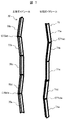
本発明の第1の実施形態について以下に説明するが、まず、乗りかごの移動中に振動を生じるガイドレールの不整な取り付け状態を図7に基づき簡単に説明する。ここではガイドレールが乗りかごの扉側とその反対の奥側の方向にずれた状態で取り付けられた不整を示している。 The first embodiment of the present invention will be described below. First, an irregular mounting state of the guide rail that generates vibration during the movement of the car will be briefly described with reference to FIG. Here, an irregularity is shown in which the guide rail is mounted in a state of being shifted in the direction of the door side of the car and the opposite side of the car.
図7において、左側ガイドレール70の単位ガイドレール70aと単位ガイドレール70bの接続部C70abは扉側に向かって曲がっており、対する右側ガイドレール71の単位ガイドレール71aと単位ガイドレール71bの接続部C71abは扉とは反対の奥側に向かって曲がっている状態を示している。そして、このような取り付け不整の場合では、この領域を乗りかごが高速度で通過すると乗りかごの移動方向の軸心周りの回転振動を励起しやすくなる。
In FIG. 7, the connecting portion C70ab between the
また、左側ガイドレール70の単位ガイドレール70dと単位ガイドレール70eの接続部C70deは扉側に向かって曲がっており、対する右側ガイドレール71の単位ガイドレール71dと単位ガイドレール71eの接続部C71deも扉側に向かって曲がっている。このような取り付け不整の場合、この領域を乗りかごが高速度で通過すると乗りかごは乗りかごの扉側とその反対の奥側に伸びる軸に並進、あるいはガイドレール側に向かって伸びる軸周りの回転振動を励起しやすくなる。
Further, a connecting portion C70de between the
したがって、ガイドレール70、71の取り付け不整を把握し、どのような振動が励起されやすいかがわかれば、それに対応してよりよい制振機構の調整が可能になる。尚、以下の説明では乗りかごの扉側とその奥側の方向を前後方向、或いはx方向とし、これに直交するガイドレール側の方向を左右方向、或いはy方向とし、乗りかごの移動方向を上下方向、或いはz方向とし、各方向の軸線をx軸、y軸、z軸として説明する。
Therefore, if the mounting irregularities of the
そして、乗りかごが移動してる途中に乗りかごに生じる振動は、上下方向と横方向(=前後方向及び左右方向)の振動がある。上下方向の振動は、主に回転系の取り付け不整によって引き起こされる。横方向の振動は、ガイドレールの曲がりや段差に基づく取り付け不整による強制変位が乗りかごに作用することによって引き起こされる。また、場合によってはつり合い重りや隣接する乗りかごとすれ違う際の風が乗りかごに作用することによって引き起こされることもある。 The vibrations generated in the car while the car is moving include vibrations in the vertical direction and the horizontal direction (= front-rear direction and left-right direction). The vibration in the vertical direction is mainly caused by improper mounting of the rotating system. Lateral vibration is caused by forced displacement acting on the car due to improper mounting due to bending of the guide rail or steps. Also, in some cases, it may be caused by the balance weight or the wind that passes between adjacent cars acting on the car.
ところで、乗りかごの走行速度が増加していくと、ガイドレールの取り付け不整によって励起される振動エネルギが増加すると共に、並進運動となる低次の振動モードのみならず、回転運動となる高次の振動モードが励起される。振動の種類としては、前後方向及び左右方向の並進運動と、各軸周りの3つの回転運動である計5つの運動があり、これらの組み合わせを含めて複数の運動(振動モード)を抑制することが必要である。また、つり合い重りや隣接する乗りかごのすれ違い時に受ける風も走行速度の増加に伴って大きくなるので、これについても考慮する必要がある。 By the way, as the traveling speed of the car increases, the vibration energy excited by the improper mounting of the guide rail increases, and not only the low-order vibration mode that is a translational motion but also the high-order that is a rotational motion. The vibration mode is excited. There are a total of five types of vibrations: translational motion in the front-rear and left-right directions, and three rotational motions around each axis. Suppress multiple motions (vibration modes) including these combinations. is necessary. Moreover, since the wind received when the counterweight and adjacent cars pass each other increases as the traveling speed increases, it is necessary to consider this as well.
このように乗りかごの走行速度の高速化が進むにつれて、乗りかごに生じる振動に対する制振作用を向上させていく必要がある。通常は、ガイドレールの据付精度の向上や風の影響を低減する乗りかご形状の採用等の対策がとられるが、これだけでは乗りかごに生じる振動に対する制振作用は不十分であり、乗りかごの振動を能動的に制御しなくてはならない。 As the traveling speed of the car is increased as described above, it is necessary to improve the damping action against the vibration generated in the car. Normally, measures such as improving the guide rail installation accuracy and adopting a car shape that reduces the influence of wind are taken, but this alone does not provide sufficient vibration suppression for the car. The vibration must be actively controlled.
更に、設置されている制振機構部の制振アクチュエータの個数が抑制すべき振動モードの個数より少ない場合、ある1つの振動モードを抑制しようとして制振アクチュエータを作動させると、その作動によって他の振動モードが逆に励起されてしまうという干渉現象を発生して制振能力に限界が生じる。抑制すべき振動モードと同数以上の制振アクチュエータとすれば良いが、制振アクチュエータの個数が増大するにしたがい制御装置での制御演算が複雑化していき、制御ゲイン等の制御パラメータの調整作業が困難となり、十分な振動抑制効果が得られないという課題や、調整作業に多くの時間を費やすという課題を生じる。 Further, when the number of vibration control actuators of the vibration control mechanism installed is smaller than the number of vibration modes to be suppressed, if the vibration control actuator is operated to suppress one vibration mode, another operation is caused by the operation. An interference phenomenon in which the vibration mode is excited in reverse occurs to limit the vibration suppression capability. The number of vibration control actuators should be equal to or greater than the number of vibration modes to be suppressed.However, as the number of vibration control actuators increases, the control calculations in the control device become more complicated, and the adjustment work of control parameters such as control gain becomes more complicated. It becomes difficult and the subject that sufficient vibration suppression effect is not acquired and the subject that spends a lot of time for adjustment work arise.
このような課題を解決すべく本実施例では、制振機構部を作動させずに予め乗りかごを昇降させて取得した加速度から、ガイドレールの取り付け不整によって乗りかごに与えられる外乱を推定し、推定された外乱に基づき制振機構部の制振アクチュエータを制御する制御量の少なくとも1つの制御パラメータの調整量を算出し、この調整量を用いて演算された制御量で制振機構部の制振アクチュエータを作動させて乗りかごを昇降させ、この時に取得した加速度が所定値以下になるまで、制御パラメータの調整量を繰り返し算出して制振機構部の制振アクチュエータに与える制御量を演算することを特徴としている。 In order to solve such a problem, in this embodiment, from the acceleration obtained by raising and lowering the car in advance without operating the vibration damping mechanism part, the disturbance given to the car due to improper mounting of the guide rail is estimated, Based on the estimated disturbance, an adjustment amount of at least one control parameter of the control amount for controlling the vibration control actuator of the vibration suppression mechanism portion is calculated, and the control amount of the vibration suppression mechanism portion is calculated using the control amount calculated using this adjustment amount. Operate the vibration actuator to raise and lower the car, and calculate the control amount to be given to the vibration control actuator of the vibration suppression mechanism by repeatedly calculating the adjustment amount of the control parameter until the acceleration acquired at this time becomes less than the predetermined value It is characterized by that.
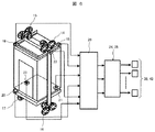
次に本発明の具体的な実施形態を図面に基づき説明する。図1において、エレベータ装置の乗りかご10はかご枠11とかご室12を有し、かご枠11の上部と下部には、制振機構部であるローラガイド機構14、15、16、17が設置されている。ローラガイド機構14、15、16、17は、昇降路に設置されるガイドレール(図7に示している)に当接しており、乗りかご10はガイドレールに沿って昇降するものである。ローラガイド機構14、15、16、17は乗りかご10の左側と右側で、かつ乗りかご10の前後方向のほぼ中央に設置されている。そして、このローラガイド機構14、15、16、17の設置位置に対応してガイドレールが昇降路壁面に取り付け固定されている。
Next, specific embodiments of the present invention will be described with reference to the drawings. In FIG. 1, a
ガイドレールは図7にある通り、単位ガイドレール70a〜70e、71a〜71e(もちろん、上下方向にこれらに接続される単位ガイドレールがあることは言うまでもない)からなっており、この単位ガイドレールは4〜5mの長さを有している。そして、単位ガイドレールは昇降路に縦方向に連結して据え付けるため、単位ガイドレールの接続点において曲がりが生じる。乗りかご10の昇降時には、単位ガイドレールの接続点の曲がりが強制変位としてローラガイド機構14、15、16、17を介して乗りかご10に作用して横方向の振動を発生させることになる。
As shown in FIG. 7, the guide rails are composed of
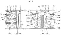
このように、ガイドレールの取り付け不整に基づく乗りかご10に作用する横方向の振動を能動的に抑制すべく、ローラガイド機構14、15、16、17には制振アクチュエータが取り付けられている。このローラガイド機構14、15、16、17の構成を図2に示している。このように制振アクチュエータによって制振力を調整するものを能動的制振機構部と呼んでいる。
As described above, the vibration guide actuators are attached to the
図2は制振機構部であるローラガイド機構14、15、16、17の一つを側面から見た図である。まず、ローラ30a、30bはガイドレールの突出部の両端面を挟み込むもので、それぞれ一対のレバー31a、31bに軸支されており、これらのレバー下端が支持台32にピン支持されている。ここで、ローラ30a、30bは、乗りかご10に横揺れが発生したり、乗客の乗り込みによって乗りかご10に偏荷重が発生しても、ガイドレールから離れないようにしなければならない。
FIG. 2 is a side view of one of the
ローラ30a、30bをガイドレールに押付けるため、レバー31a、31bに固定されたコイルばね33a、33bが自然長から圧縮した状態で取付けられている。また、乗りかごの異常な傾きを防ぐため、レバー31a、31bが一定の回転角を超えないようにそれぞれ弾性体34a、34bが設置され、ストッパの役割を果たしている。更に、ローラ30a、30bに直交するローラ30cが設けられており、ローラ30cはガイドレールの突出部の先端に密着して回転するものである。
In order to press the
ローラガイド機構の支持台32に結合された支持板35には、制振アクチュエータ36が取付けられている。この制振アクチュエータ36は、例えばボールネジ37とカップリング( 図示せず)を介して可動体38と直結されている。ここで、可動体38は、制振アクチュエータ36と同様に支持板35上に、例えばリニアガイド39を介して取付けられ、ローラ30a、30bの揺動方向と同一方向のみに水平移動することができる。
A
可動体38には、その両端において左右に一対のロッド40a、40bが結合されており、コイルばね33a、33bの端部が、このロッド端に設けたナット41a、41bにより固定されている。このような構成によれば、制振アクチュエータ36に指令を与えて、可動体37の水平動作を制御することでコイルばね33a、33bの圧縮力を変えることができる。
A pair of rods 40a and 40b are coupled to the
また、ローラ30cも実質的に同じ構成になっており、支持板35には、制振アクチュエータ42が取付けられている。この制振アクチュエータ42は、例えばボールネジ43とカップリング( 図示せず)を介して可動体44と直結されている。ここで、可動体44は、アクチュエータ42と同様に支持板35上に、例えばリニアガイド45を介して取付けられ、ローラ30cの揺動方向と同一方向のみに水平移動することができる。
Further, the
可動体44には、その一端においてロッド46が結合されており、コイルばね47の端部が、このロッド端に設けたナット48により固定されている。このような構成によれば、制振アクチュエータ42に指令を与えて、可動体44の水平動作を制御することでコイルばね47の圧縮力を変えることができる。
A
ここで、アクチュエータ36、42への駆動信号は、乗りかご10に設置された後述する加速度センサの出力から制御装置で演算されて決定されるものである。尚、図示したローラガイド機構14、15、16、17とは異なり、それぞれのローラ30a〜30cの押し付け力を個別のモータによって調整しても良く、また、制振アクチュエータとしてリニアモータを用いても良いものである。
Here, the drive signals to the
図1に戻って、乗りかご10にはガイドレールから与えられる振動を検出する加速度検出器(以下、加速度センサという)が複数個設けられている。具体的には、乗りかご10の天井側の外側上面部の対角部分には加速度センサ18、19が設けられている。同様に乗りかご10の床側の外側下面部の対角部分には加速度センサ20、21が設けられている。加速度センサ18、19の配置関係と加速度センサ20、21の配置関係は同じ関係に設定されており、それぞれの加速度センサ18〜21は、天井側の外側表面と床側の外側表面の対角部分の角部に配置されている。これらの加速度センサ18〜21はx方向(前後方向)の加速度を検出するものである。これらの加速度センサは必ずしも角部に配置されていなくても良い。
Returning to FIG. 1, the
また、かご枠11の天井側の外表面に配置されたローラガイド機構14の配置部分には加速度センサ22が配置され、これと対角の位置にあるかご枠11の床側の外表面に配置されたローラガイド機構17の配置部分にも加速度センサ23が配置されている。これらの加速度センサ22、23はy方向(左右方向)の加速度を検出するものである。
Further, an
加速度センサ18〜21で検出された加速度は第1制御装置24に入力され、この検出された加速度に基づいて乗りかご1の振動を抑制するための駆動信号(制御指令)を出力する。第1制御装置24は乗りかご1の前後方向(=x方向)の振動を抑制するための制振アクチュエータ36の駆動信号を出力する機能を備えている。第1制御装置24は種々の機能を実行するための制御装置であるが、ここでは乗りかごの振動を抑制する制振機能を実行する制御装置として説明する。第1制御装置24は基本的には、加速度から外乱力を求める外乱力演算機能部26Aと、制御パラメータである制御ゲインを求める制御パラメータ演算機能部26Bと、この制御パラメータ演算機能部26Bからの制御ゲインを用いて制御量である駆動信号を演算する制御量演算機能部26Cを有している。
The acceleration detected by the
同様に、加速度センサ22〜23で検出された加速度は第2制御装置25に入力され、この検出された加速度に基づいて乗りかご1の振動を抑制するための駆動信号(制御指令)を出力する。第2制御装置25は乗りかご1の左右方向(=y方向)の振動を抑制するための制振アクチュエータ42の駆動信号を出力する機能を備えている。第2制御装置25も同様に種々の機能を実行するための制御装置であるが、乗りかごの振動を抑制する制振機能を実行する制御装置として説明する。第2制御装置25も、基本的には、加速度から外乱力を求める外乱力演算機能部27Aと、制御パラメータである制御ゲインを求める制御パラメータ演算機能部27Bと、この制御パラメータ演算機能部27Bからの制御ゲインを用いて制御量である駆動信号を制御演算する制御量演算機能部27Cを有している。
Similarly, the acceleration detected by the
ここで、本実施例では、x方向に関する振動を抑制する第1制御装置24と、y方向に関する振動を抑制する第2制御装置25に分割されている。
Here, in this embodiment, it is divided into a
本実施例では、第1制御装置24、第2制御装置25及びローラガイド機構14、15、16、17を纏めて制振機構ということにする。そして、第1制御装置24と第2制御装置25は機能的に同じ構成を採用しており、乗りかご10に作用する前後方向と左右方向の振動を抑制するために、前後方向では制振アクチュエータ36に駆動信号を送り、左右方向では制振アクチュエータ42に駆動信号を送っている。したがって、第1制御装置24と第2制御装置25では各制振アクチュエータ36、42の駆動信号を算出するための制御演算が実行されている。
In this embodiment, the
制御装置の一例として第2制御装置25の機能構成を図3に基づいて説明すると、第2制御装置25は4つの単位制御装置25A、25B、25C、25Dから構成されている。これは左右方向(=y方向)に関する2つの加速度センサ22、23の入力から左右方向に関する2つの制振アクチュエータ42への駆動信号を決定するものである。それぞれの単位制御装置25A〜25Dは、加速度による外乱力F11、F21、F12、F22を演算する外乱力演算機能部27Aと、制御ゲインであるK11、K21、K12、K22を演算する制御パラメータ演算機能部27Bと、周波数特性をもつ伝達関数G(s)よりなる制御量演算機能部27Cとから構成されている。伝達関数G(s)は各単位制御装置25A〜25Dとも共通であり、異なるのは制御ゲインである。制御ゲインK11、K21、K12、K22は伝達関数G(s)に反映され、これによって駆動信号が演算されて出力されるものである。
The functional configuration of the
制御パラメータというのは本実施例では制御ゲインのことであり、y方向に関する各単位制御装置25A〜25Dには4つ(複数)の制御パラメータが存在する。したがって、ガイドレールの取り付け不整によって引き起こされる振動モードに応じて、各制御パラメータの値が正確に決定されれば振動を効果的に抑制することができる。当然のことであるが、第1制御装置24においても各制御パラメータの値が正確に決定されれば振動を効果的に抑制することができることは言うまでもない。
The control parameter is a control gain in this embodiment, and there are four (plural) control parameters in each of the
このように、第1制御装置24、第2制御装置25は図3に例示してある通り、複数の単位制御装置を有しており、複数の制御パラメータの調整量を算出して制振アクチュエータの駆動信号の演算に使用されるものである。
As described above, the
そして、上述したような現場据え付け段階での調整作業が困難になる、或いは調整作業効率が低下するという課題を解決するために、本実施例では以下の調整方法を提案するものである。図4は本実施例になる制御パラメータを自動的に調整するための調整工程を説明する調整フローチャートを示している。 And in order to solve the subject that adjustment work in the field installation stage as mentioned above becomes difficult, or adjustment work efficiency falls, this example proposes the following adjustment methods. FIG. 4 shows an adjustment flowchart for explaining an adjustment process for automatically adjusting the control parameters according to this embodiment.
まず、ステップS40でローラガイド機構14、15、16、17等の制振機構部による制振制御をかけない状態で乗りかごを所定の速度で昇降させ、この時の乗りかご10に取り付けた加速度センサ18〜23より各加速度センサ18〜23毎の走行データAを取得する。この走行データAは、各加速度センサ18〜23によって検出された、乗りかご10に作用する少なくとも前後方向及び左右方向の加速度を示している。これによってガイドレールにどのような方向の加速度を生じる取り付け不整が生じているか、或いはその取り付け不整がどの程度のものかが推定できる。
First, in step S40, the car is moved up and down at a predetermined speed without vibration control by the vibration control mechanisms such as the
例えば、前後方向の加速度が大きい領域(昇降路に取り付けたガイドレールの縦方向位置)があると、その領域でガイドレールが開閉扉の方向、或いは奥側の方向に傾いて取り付けられていることが推定できる。同様に、左右方向でもガイドレールの取り付け不整が推定できる。 For example, if there is a region where the acceleration in the front-rear direction is large (the vertical position of the guide rail attached to the hoistway), the guide rail is attached to the region in the direction of the door or the back side in that region. Can be estimated. Similarly, guide rail mounting irregularities can be estimated in the left-right direction.
次にステップS41で、走行データAによる各加速度センサ18〜23毎の加速度からガイドレールの取り付け不整に基づく外乱力を推定する。基本的には以下のような関係式からガイドレールの取り付け不整に基づく外乱力の推定を行うことができる。
Next, in step S41, the disturbance force based on the improper mounting of the guide rail is estimated from the acceleration of each of the
加速度センサ18〜23の設置位置での加速度情報xsと乗りかご10の重心周りの運動加速度x0との関係が式(1)で表されたとする。
Relationship between the motion acceleration x 0 around the center of gravity of the
![]()
![]()
ここで、Tは座標変換マトリクスであり、各加速度センサの設置位置と乗りかごの重心との関係を示している。 Here, T is a coordinate conversion matrix, and shows the relationship between the installation position of each acceleration sensor and the center of gravity of the car.
そして、乗りかご10の運動方程式は以下の式(2)で表すことができる。
The equation of motion of the
![]()
![]()
ここで、Mは乗りかご系の質量マトリクス、Cは減衰マトリクス、Kは剛性マトリクスであり、Frはガイドレールの取り付け不整より発生する外乱力を表している。 Here, M car system mass matrix, C is the attenuation matrix, K is a stiffness matrix, F r represents the disturbance force generated from the mounting of the guide rail irregularities.
更に式(1)を式(2)の第1項に代入して整理すると、 Further substituting equation (1) into the first term of equation (2) and rearranging,
![]()
![]()
となり、これは加速度センサで検出された加速度からガイドレールによる外乱力を推定できることを意味している。ただし、式(3)の This means that the disturbance force due to the guide rail can be estimated from the acceleration detected by the acceleration sensor. However, in equation (3)
![]()
![]()
は加速度センサの加速度を積分して得られるものである。以上のような演算によって、ガイドレールの取り付け不整による外乱力Frが推定できると、いずれの振動モードが引き起こされやすいかが判断できる。このように、各加速度センサ18〜23によって、ガイドレールの取り付け不整によって生じる複数の振動モードの内のいずれかを推定することができる。
Is obtained by integrating the acceleration of the acceleration sensor. If the disturbance force Fr due to improper mounting of the guide rail can be estimated by the above calculation, it can be determined which vibration mode is likely to be caused. As described above, each of the
次に、ステップS42では、外乱力に基づいて推定された引き起こされやすい振動モードに関係する制御パラメータの調整量(制御ゲインの大きさ)の演算を行い、この演算された調整量を反映した制御量は出力回路に設定される。尚、この調整量は乗りかごに作用する加速度を減少させる成分を持った調整量に設定されることは言うまでもない。もちろん、励起される振動モードが複数あった場合は、これに対応した制御パラメータの調整量の演算が行われることになる。そして、この制御パラメータの調整量は、予め振動モードに対応して設定しておいた複数の調整量から適切な調整量を選定して得られるものであり、調整量は電子的なメモリに形成されたテーブルを参照して求めることができる。制御パラメータの調整量が求まると、制振アクチュエータ36、42の駆動信号の最終的な制御演算が各制御装置24、25によって実行されることになる。
Next, in step S42, the control parameter adjustment amount (the magnitude of the control gain) related to the easily caused vibration mode estimated based on the disturbance force is calculated, and the control reflecting the calculated adjustment amount is performed. The quantity is set in the output circuit. Needless to say, this adjustment amount is set to an adjustment amount having a component that reduces the acceleration acting on the car. Of course, if there are a plurality of vibration modes to be excited, the control parameter adjustment amount corresponding to this is calculated. The adjustment amount of the control parameter is obtained by selecting an appropriate adjustment amount from a plurality of adjustment amounts set in advance corresponding to the vibration mode. The adjustment amount is formed in an electronic memory. Can be obtained by referring to the table. When the adjustment amount of the control parameter is obtained, the final control calculation of the drive signals of the
次に、ステップS43ではステップS42で求められた制振アクチュエータ36、42の駆動信号で制振アクチュエータ36、42を駆動してローラガイド機構14、15、16、17等の制振機構部による制振制御を実行する。そして、この状態で乗りかご10をステップS40と同じ速度条件で昇降させ、この時の乗りかご10に取り付けた加速度センサ18〜23より各加速度センサ18〜23毎の走行データBを取得する。この走行データBはステップS42によって制御パラメータが調整された後なので走行データAよりも加速度が小さく改善されている。
Next, in step S43, the
次に、ステップS44に進み、走行データBの加速度が許容基準値より小さいかどうかが判断される。ステップS44で走行データBの加速度が許容基準値より小さいと判断されると、ステップS42で設定した制御パラメータの調整量の設定が成功したとしてエンドに抜ける。これによって、制御パラメータの値が確定して以後の実際の運行で使用されるものとなる。この場合も、複数の振動モードがあった場合はこれらに対応する加速度が許容基準値より小さいかどうかが判断される。 Next, it progresses to step S44 and it is judged whether the acceleration of the driving | running | working data B is smaller than an allowable reference value. If it is determined in step S44 that the acceleration of the travel data B is smaller than the allowable reference value, the control parameter adjustment amount set in step S42 is successfully set and the process ends. As a result, the value of the control parameter is determined and used in the subsequent actual operation. Also in this case, when there are a plurality of vibration modes, it is determined whether or not the acceleration corresponding to these vibration modes is smaller than the allowable reference value.
一方、ステップS44で走行データBの加速度が許容基準値より大きいと判断されると、ステップS42で設定した制御パラメータの調整量の設定が未だ成功していないとしてステップS45に進む。ステップS45では、ステップS41で推定された制振制御を実行していないときの外乱力と、制振制御を実行した時の走行データBによって制御パラメータの調整量の再演算を実行する。すなわち、外乱力から導かれた振動モードを対象に、ステップS42で求めた制御パラメータの調整量に対して、更に加速度を抑制することができる調整量に変更する演算を実行する。 On the other hand, if it is determined in step S44 that the acceleration of the travel data B is greater than the allowable reference value, the control parameter adjustment amount set in step S42 has not yet been set, and the process proceeds to step S45. In step S45, the control parameter adjustment amount is recalculated based on the disturbance force when the vibration suppression control estimated in step S41 is not executed and the travel data B when the vibration suppression control is executed. That is, for the vibration mode derived from the disturbance force, the calculation for changing the adjustment amount of the control parameter obtained in step S42 to an adjustment amount that can further suppress the acceleration is executed.
例えば、外乱力と走行データとの関係は予めモデルとして構築されており、このモデルに外乱力と走行データを代入してやることで調整量を求めることができる。この他に、乗りかご10を走行して得られた走行データBの加速度が要求される所定の許容基準値に収束する方向に、調整量を段階的に順次更新していく方法をとることもできる。要は、ステップS41で推定された外乱力から求まる振動モードを対象に、走行データBの加速度が要求される所定の許容基準値以下になるまで、制御パラメータの調整量を調整すれば良いものである。
For example, the relationship between disturbance force and travel data is built in advance as a model, and the adjustment amount can be obtained by substituting the disturbance force and travel data into this model. In addition to this, a method may be used in which the adjustment amount is sequentially updated step by step so that the acceleration of the travel data B obtained by traveling the
そして、再びステップS43〜S45を実行して適切な制御パラメータの調整量を探索する処理を実行する。これらのステップを繰り返して、乗りかご10に作用する加速度が所定の許容基準値より小さくなるまで調整量の演算を行い、最期に乗りかご10に作用する加速度が所定の許容基準値より小さくなるとエンドに抜けるものである。これによって、最終的に制御パラメータの値が確定して以後の実際の運行で使用されるものとなる。
Then, steps S43 to S45 are executed again to execute a process of searching for an appropriate control parameter adjustment amount. By repeating these steps, the adjustment amount is calculated until the acceleration acting on the
ここで、上記した調整フローチャートはガイドレールの取り付け不整に基づく外乱力から振動モードを推定するので、すべての振動モードについて乗りかごに作用する加速度が所定の許容基準値より小さくなるまで調整フローチャートの実行が継続されるものである。 Here, since the above-described adjustment flowchart estimates the vibration mode from the disturbance force based on the improper mounting of the guide rail, the adjustment flowchart is executed until the acceleration acting on the car becomes smaller than a predetermined allowable reference value for all vibration modes. Will continue.
このように、本実施例では、制振機構部を作動させずに乗りかごを昇降させて取得した加速度からガイドレールによって乗りかごに与えられる外乱力を推定し、推定された外乱力に基づき制振機構部の制振アクチュエータを制御する制御量の少なくとも1つの制御パラメータの調整量を算出し、この調整量を用いて演算された制御量で制振機構部の制振アクチュエータを作動させて乗りかごを昇降させ、この時に取得した加速度が所定値以下になるまで、制御パラメータの調整量を繰り返し算出して制振機構部の制振アクチュエータに与える制御量を演算するものである。したがって、複数の振動モードを抑制する複雑な制御装置であっても、据え付け現場での調整を容易にして据え付け完了までの期間を短縮することができるものとなる。 As described above, in this embodiment, the disturbance force applied to the car by the guide rail is estimated from the acceleration obtained by raising and lowering the car without operating the vibration damping mechanism, and the damping force is based on the estimated disturbance force. Calculate an adjustment amount of at least one control parameter of the control amount for controlling the vibration control actuator of the vibration mechanism unit, and operate the vibration control actuator of the vibration control mechanism unit with the control amount calculated using this adjustment amount. The car is moved up and down, and the amount of control parameter adjustment is repeatedly calculated until the acceleration acquired at this time falls below a predetermined value, and the control amount given to the vibration control actuator of the vibration control mechanism is calculated. Therefore, even in a complicated control device that suppresses a plurality of vibration modes, adjustment at the installation site can be facilitated and the period until the installation is completed can be shortened.
ここで、本実施例では、外乱力を推定するためステップS40においては、制振機構部による制振制御をかけないで乗りかごを所定の走行速度で昇降させ、この時の乗りかご10に取り付けた加速度センサ18〜23より走行データAを取得するようにしている。しかしながら、この時の乗りかご10の速度はガイドレールの取り付け不整領域の数、及びその位置によって調整された走行速度であることが望ましい。このように外乱力を推定する走行速度を変えることによって、更に制振効果を高める調整量を早く求めることができる。
Here, in this embodiment, in order to estimate the disturbance force, in step S40, the car is moved up and down at a predetermined traveling speed without being subjected to vibration damping control by the vibration damping mechanism, and attached to the
ガイドレールによる外乱力を推定するために、ステップS40で示す制振制御を実行しないで乗りかご10を昇降させる際に、その走行速度を乗りかご系の固有振動数に一致するように設定すると良い。この走行速度は、ガイドレール長に乗りかごの固有振動数を乗ずれば導き出せる。乗りかご10がガイドレール上を移動する過程で、制振すべき対象となる振動モードが複数存在する場合、それぞれの振動モードに対応する走行速度で走行データAを取得することは有効である。
In order to estimate the disturbance force due to the guide rail, when the
走行データAにおいて、乗りかごに作用する加速度が大きくなる箇所が、制振すべき固有振動数の振動モードを引き起こす原因となるガイドレールの取り付け不整領域であることが推測できる。よって、この固有振動数に対応した走行速度で乗りかごを走行させて走行データAをとると、昇降路中のガイドレールがどの位置でどのような形態の取り付け不整が生じているかを容易に把握することが可能となる。 In the travel data A, it can be inferred that the portion where the acceleration acting on the car is large is a guide rail mounting irregular region that causes the vibration mode of the natural frequency to be damped. Therefore, when the car is run at a running speed corresponding to this natural frequency and the running data A is taken, it is easy to know what type of mounting irregularities occur at which position of the guide rail in the hoistway. It becomes possible to do.
したがって、ガイドレールの取り付け不整形態、及び乗りかごの走行状態から最も引き起こされやすい振動モードを導き出し、その振動モードに適した制御パラメータを算出することができる。また、ガイドレールの取り付け不整形態、及び乗りかごの走行状態からから乗りかご10に影響を与える振動モードが発生するガイドレールの取り付け不整領域(昇降路の縦方向位置)を推定することができる。このような情報から、引き起こされやすい振動モードに対応した制御パラメータの調整量を導き出しておき、乗りかご10の走行中に対応する振動モードが発生するガイドレールの取り付け不整領域で、算出しておいた制御パラメータの調整量を切り替えることによって制振機構の振動抑制効果を高めることが可能になる。もちろん、振動モードの発生領域が複数ある場合は、その領域毎に走行速度を変えてやることも可能である。この場合、領域毎に制御パラメータの調整量を導き出すことも可能である。
Therefore, it is possible to derive the vibration mode that is most likely to be caused from the improper configuration of the guide rail and the traveling state of the car, and to calculate the control parameters suitable for the vibration mode. In addition, it is possible to estimate a guide rail attachment irregularity region (vertical position of the hoistway) in which a vibration mode affecting the
また、ガイドレール長と乗りかごの固有振動数から導き出した複数の走行速度に基づいて、それぞれの速度で乗りかごを昇降させ、加速度センサから最大加速度が発生している走行速度を導き出し、この時の走行速度に対応して図4に示した手法によって制御パラメータの調整量を求めることも有効である。これは走行速度によって外乱力の大きさが変化するので、走行速度が大きいほど制振効果が強くなる調整量を使用することが有利である。もちろん、最大加速度だけでなく、それぞれの加速度に対応した調整量を用いることも可能である。 Also, based on the multiple travel speeds derived from the guide rail length and the natural frequency of the car, the car is moved up and down at each speed, and the travel speed at which the maximum acceleration is generated is derived from the acceleration sensor. It is also effective to obtain the adjustment amount of the control parameter by the method shown in FIG. Since the magnitude of the disturbance force changes depending on the traveling speed, it is advantageous to use an adjustment amount that increases the vibration damping effect as the traveling speed increases. Of course, it is possible to use not only the maximum acceleration but also an adjustment amount corresponding to each acceleration.
更に、昇降路の高さ毎に複数の高さ領域に分割し、その分割された高さ領域毎に最大加速度が発生している走行速度を算出し、図4に示す調整フローチャートに沿って、上記した走行速度で走行させた時の走行データに基づいて制御パラメータの調整量を求め、高さ領域毎に制御パラメータの調整量を切り替えることも可能である。 Furthermore, it is divided into a plurality of height regions for each height of the hoistway, the travel speed at which the maximum acceleration is generated for each of the divided height regions is calculated, and along the adjustment flowchart shown in FIG. It is also possible to obtain the adjustment amount of the control parameter based on the travel data when traveling at the travel speed described above, and to switch the adjustment amount of the control parameter for each height region.
尚、本実施例では第1制御装置24と第2制御装置25を個別に設けているが、第1制御装置24と第2制御装置25を纏めて一つの制御装置として構成することもできる。このように一つの制御装置にまとめると、第1制御装置24と第2制御装置25を繋ぐ配線にノイズが乗るといった影響を少なくできる、第1制御装置24と第2制御装置25の相互のキャリブレーションが容易になるといった効果が期待できる。
In the present embodiment, the
次に本発明の第2の実施形態について説明する。実施例1では制御装置24、25に、外乱力演算機能部26A、27Aと、制御ゲイン演算機能部26B、27Bと制御量演算機能部26C、27Cを有しているが、本実施例では外乱力演算機能部26A、27Aを分離した点で、実施例1と異なっているものである。
Next, a second embodiment of the present invention will be described. In the first embodiment, the
図5に示すように、x軸方向のガイドレールの取り付け不整に基づく外乱力を推定する外乱力演算機能部26Aを第1制御装置24から分離し、この外乱力演算機能部26Aからの出力を第1制御装置24に入力し、これに基づいて、第1制御装置24に設けられた制御パラメータ演算機能部26Bはx方向の制御パラメータの調整量を演算する。更に、制御パラメータ演算機能部26Bからの制御パラメータの調整量は制御量演算機能部26Cに入力される。
As shown in FIG. 5, a disturbance force
更に、y軸方向のガイドレールの取り付け不整に基づく外乱力を推定する外乱力演算機能部27Aを第1制御装置24から分離し、この外乱力演算機能部27Aからの出力を第2制御装置25に入力し、これに基づいて、第2制御装置25に設けられた制御パラメータ演算機能部27Bはy方向の制御パラメータの調整量を演算する。更に、制御パラメータ演算機能部27Bからの制御パラメータの調整量は制御量演算機能部27Cに入力される。この実施例においても、実施例1と同様の作用、効果を奏することができるものである。
Further, the disturbance force
更に、実施例1では、外乱力演算機能部26A、27Aと、制御ゲイン演算機能部26B、27Bと制御量演算機能部26C、27Cを一体的に有しているが、外乱力演算機能部26A、27Aと、制御ゲイン演算機能部26B、27Bと制御量演算機能部26C、27Cをそれぞれ別体に構成することも可能である。
Further, in the first embodiment, the disturbance force
次に本発明の第3の実施形態について説明する。実施例1では制御装置24、25によって制御パラメータの調整値を演算して制御量に反映するオンボード方式であるが、本実施例ではエレベータ装置の据え付け者が有する制御パラメータ調整装置によって、制御パラメータの調整量を求め、これを制御装置24、25に転送して調整作業を行う方式である。制御パラメータ調整装置は携帯型の汎用コンピュータ(パーソナルコンピュータや携帯タブレット)や、制御パラメータ調整ソフトを内蔵した専用の携帯型タブレットが使用できる。
Next, a third embodiment of the present invention will be described. In the first embodiment, the adjustment values of the control parameters are calculated by the
制御パラメータ調整装置28は第1制御装置24、第2制御装置25とは分離して据え付け者が携帯するものである。制御パラメータ調整装置28は外乱力演算機能部26A、27Aと、制御パラメータ演算機能部26B、27Bを備えており、演算して求められた制御パラメータの調整量を第1制御装置24、第2制御装置25に転送するものである。このため、第1制御装置24、第2制御装置25は外乱演算機能部26A、27Aと、制御パラメータ演算機能部26B、27Bを備えていない。
The control
そして、調整作業において、据え付け者は加速度センサ18〜23と第1制御装置24、第2制御装置25とを信号線で制御パラメータ調整装置28に接続する。その後、図4に示した制御フローのステップを実行することによって得られた制御パラメータの調整量を第1制御装置24、第2制御装置25に送って制振制御を実行するものである。
In the adjustment work, the installer connects the
つまり、制御パラメータ調整装置28は、制振機構部を作動させずに乗りかご10を昇降させて取得した加速度からガイドレールによって与えられる外乱を推定し、推定された外乱に基づき制振機構部の制振アクチュエータ36,42を制御する制御量の少なくとも1つの制御パラメータの調整量を算出して制御装置24,25に転送する。そして、制御装置24,25は、転送されてきた調整量を用いて演算した制御量で制振機構部の制振アクチュエータを作動させて乗りかごを昇降させる。更に、制御パラメータ調整装置28は図4に示す通り、この時に取得した加速度が所定値以下になるまで、制御パラメータの調整量を繰り返し算出して制御装置24,25に与えるように動作するものである。
In other words, the control
もちろん、この場合もガイドレールの取り付け不整に基づく外乱力から振動モードを推定するので、すべての振動モードについて加速度が基準値より小さくなるまで継続されるものである。 Of course, in this case as well, the vibration mode is estimated from the disturbance force based on the improper mounting of the guide rail, so that the acceleration is continued until the acceleration becomes smaller than the reference value for all vibration modes.
尚、制御パラメータ調整措置28は携帯しないで、それぞれの制御装置24、25が設けられている制御盤に取り付けられていても良いものである。制御盤に取り付けられている場合は、据え付け者が制御パラメータ調整措置28から最終的な制御パラメータの調整量を取り出せるように構成することもできる。この場合は、制御パラメータ調整措置28に、読み出し用のコネクタを設けることで実施できるものである。
Note that the control
以上説明した通り、本発明は、制振機構部を作動させずに乗りかごを昇降させて取得した加速度からガイドレールによって与えられる外乱を推定し、推定された外乱に基づき制振機構部の制振アクチュエータを制御する制御量の制御パラメータの調整量を算出し、この調整量を用いて演算された制御量で制振機構部の制振アクチュエータを作動させて乗りかごを昇降させ、この時に取得した加速度が所定値以下になるまで、制御パラメータの調整量を繰り返し算出して制振機構部の制振アクチュエータに与える制御量を演算するところにある。 As described above, the present invention estimates the disturbance given by the guide rail from the acceleration acquired by raising and lowering the car without operating the vibration damping mechanism, and the damping mechanism is controlled based on the estimated disturbance. Calculate the control parameter adjustment amount for controlling the vibration actuator, and use this adjustment amount to operate the vibration control actuator of the vibration control mechanism with the control amount calculated. The amount of control parameter adjustment is repeatedly calculated until the acceleration is less than or equal to a predetermined value, and the amount of control applied to the vibration control actuator of the vibration control mechanism is calculated.
これによれば、複数の振動モードを抑制する制御装置であっても、据え付け現場での調整を容易にして据え付け完了までの期間を短縮することができるようになる。 According to this, even in a control device that suppresses a plurality of vibration modes, adjustment at the installation site can be facilitated and the period until the installation is completed can be shortened.
10…乗りかご、11…かご枠、12…かご室、13…開閉扉、14〜17…制振機構部(ローラガイド機構)、18〜23…加速検出器、24…第1制御装置、25…第2制御装置、25A〜25D……単位制御装置、26A、27A…外乱力演算機能部、26B、27B…制御パラメータ演算機能部、26C、27C…制御量演算機能部、36、42……制振アクチュエータ。
DESCRIPTION OF
Claims (8)
前記制御装置は、
前記制振機構部を作動させずに前記乗りかごを昇降させて取得した加速度から前記ガイドレールによって与えられる外乱を推定し、
推定された外乱に基づき前記制振機構部の制振アクチュエータを制御する制御量の少なくとも1つの制御パラメータの調整量を算出し、
この調整量を用いて演算された制御量で前記制振機構部の前記制振アクチュエータを作動させて前記乗りかごを昇降させ、この時に取得した加速度が所定値以下になるまで、制御パラメータの調整量を繰り返し算出して前記制振アクチュエータに与える制御量を演算すると共に、
更に、前記制御装置は、
前記乗りかごが前記ガイドレール上を移動する過程で複数の振動モード発生領域が存在する場合、前記ガイドレールのガイドレール長と前記乗りかごの複数の振動モードの固有振動数から導き出した複数の走行速度に基づいて前記乗りかごを昇降させ、
前記加速度検出器によって検出された最大加速度から前記ガイドレールによって与えられる外乱を推定し、
推定された外乱に基づき前記制振アクチュエータを制御する制御量の制御パラメータの調整量を算出する
ことを特徴とするエレベータ装置。 A pair of guide rails provided in the hoistway, a car that moves up and down along the guide rail, an acceleration detector that detects vibrations of the car, and a control that actively suppresses vibrations of the car. In an elevator apparatus comprising a vibration control mechanism and a control device that controls the vibration control mechanism to suppress vibration of the car based on the output of the acceleration detector.
The controller is
Estimating the disturbance given by the guide rail from the acceleration obtained by raising and lowering the car without operating the vibration damping mechanism,
Calculating an adjustment amount of at least one control parameter of a control amount for controlling the vibration damping actuator of the vibration damping mechanism based on the estimated disturbance;
The control parameter is adjusted until the acceleration obtained at this time is less than or equal to a predetermined value by operating the vibration control actuator of the vibration control mechanism unit with the control amount calculated using the adjustment amount to raise and lower the car. While calculating the amount repeatedly and calculating the control amount given to the vibration control actuator ,
Furthermore, the control device comprises:
When there are a plurality of vibration mode generation regions in the process of moving the car on the guide rail, a plurality of travels derived from the guide rail length of the guide rail and the natural frequencies of the vibration modes of the car Raise and lower the car based on speed,
Estimating the disturbance provided by the guide rail from the maximum acceleration detected by the acceleration detector;
An elevator apparatus that calculates an adjustment amount of a control parameter of a control amount that controls the vibration damping actuator based on the estimated disturbance .
前記制御装置は、The control device includes:
前記制振機構部を作動させずに前記乗りかごを昇降させて取得した加速度から前記ガイドレールによって与えられる外乱を推定し、Estimating the disturbance given by the guide rail from the acceleration obtained by raising and lowering the car without operating the vibration damping mechanism,
推定された外乱に基づき前記制振機構部の制振アクチュエータを制御する制御量の少なくとも1つの制御パラメータの調整量を算出し、Calculating an adjustment amount of at least one control parameter of a control amount for controlling the vibration damping actuator of the vibration damping mechanism based on the estimated disturbance;
この調整量を用いて演算された制御量で前記制振機構部の前記制振アクチュエータを作動させて前記乗りかごを昇降させ、この時に取得した加速度が所定値以下になるまで、制御パラメータの調整量を繰り返し算出して前記制振アクチュエータに与える制御量を演算すると共に、The control parameter is adjusted until the acceleration obtained at this time is less than or equal to a predetermined value by operating the vibration control actuator of the vibration control mechanism unit with the control amount calculated using the adjustment amount to raise and lower the car. While calculating the amount repeatedly and calculating the control amount given to the vibration control actuator,
更に、前記制御装置は、Furthermore, the control device comprises:
前記昇降路を高さ毎に複数の高さ領域に分けて前記加速度検出器で加速度を検出し、Dividing the hoistway into a plurality of height regions for each height and detecting acceleration with the acceleration detector,
前記高さ領域毎に最大加速度が発生している走行速度を算出し、その走行速度に対応して発生する加速度に応じて前記制振アクチュエータを制御する制御量の制御パラメータの調整量を算出するA travel speed at which the maximum acceleration is generated for each height region is calculated, and an adjustment amount of a control parameter for controlling the vibration control actuator is calculated according to the acceleration generated corresponding to the travel speed.
ことを特徴とするエレベータ装置。An elevator apparatus characterized by that.
前記制振機構部を作動させずに前記乗りかごを昇降させる時の走行条件と、前記制振機構部を作動させて前記乗りかごを昇降させる時の走行条件とを同じ条件とするThe running conditions when raising and lowering the car without operating the damping mechanism and the running conditions when raising and lowering the car by operating the damping mechanism are the same conditions.
ことを特徴とするエレベータ装置。An elevator apparatus characterized by that.
前記制御装置は、少なくとも前記乗りかごの前後方向の振動を抑制する前記制振機構部を制御する第1の制御装置と、少なくとも前記乗りかごの左右方向の振動を抑制する前記制振機構部を制御する第2の制御装置とからなり、The control device includes: a first control device that controls at least the vibration control mechanism unit that suppresses vibration in the longitudinal direction of the car; and at least the vibration control mechanism unit that suppresses vibration in the left-right direction of the car. A second control device for controlling,
前記第1の制御装置は、推定された前後方向の外乱に基づき前記制振機構部の前後方向の振動を抑制する第1の制振アクチュエータを制御する制御量の少なくとも1つの制御パラメータの調整量を算出し、この調整量を用いて演算された制御量で前記第1の制振アクチュエータを作動させて前記乗りかごを昇降させ、この時に取得した加速度が所定値以下になるまで、制御パラメータの調整量を繰り返し算出して前記第1の制振アクチュエータに与える制御量を演算し、The first control device adjusts at least one control parameter of a control amount for controlling the first vibration control actuator that suppresses vibration in the front-rear direction of the vibration control mechanism based on the estimated front-rear disturbance. The first damping actuator is operated with a control amount calculated using this adjustment amount to raise and lower the car, and the control parameter Repetitively calculating an adjustment amount to calculate a control amount to be given to the first vibration damping actuator;
前記第2の制御装置は、推定された左右方向の外乱に基づき前記制振機構部の左右方向の振動を抑制する第2の制振アクチュエータを制御する制御量の少なくとも1つの制御パラメータの調整量を算出し、この調整量を用いて演算された制御量で前記第2の制振アクチュエータを作動させて前記乗りかごを昇降させ、この時に取得した加速度が所定値以下になるまで、前記制御パラメータの調整量を繰り返し算出して第2制振アクチュエータに与える制御量を演算するThe second control device adjusts at least one control parameter of a control amount for controlling the second vibration control actuator that suppresses the vibration in the horizontal direction of the vibration control mechanism based on the estimated horizontal disturbance. The control parameter is calculated until the car is moved up and down by operating the second vibration damping actuator with a control amount calculated using the adjustment amount, and the acceleration acquired at this time becomes a predetermined value or less. The control amount given to the second vibration control actuator is calculated by repeatedly calculating the adjustment amount
ことを特徴とするエレベータ装置。An elevator apparatus characterized by that.
前記制御装置とは分離された制御パラメータ調整装置を前記制御装置と前記加速度検出器に接続し、前記制御パラメータ調整装置は、
前記制振機構部を作動させずに前記乗りかごを昇降させて取得した加速度から前記ガイドレールによって与えられる外乱を推定し、
推定された外乱に基づき前記制振機構部の制振アクチュエータを制御する制御量の少なくとも1つの制御パラメータの調整量を算出して前記制御装置に転送し、
前記制御装置が転送された調整量を用いて演算した制御量で前記制振アクチュエータを作動させて前記乗りかごを昇降させた時、この時に取得した加速度が所定値以下になるまで、制御パラメータの調整量を繰り返し算出して前記制御装置に転送すると共に、
更に、前記制御パラメータ調整装置は、
前記乗りかごが前記ガイドレール上を移動する過程で複数の振動モード発生領域が存在する場合、前記ガイドレールのガイドレール長と前記乗りかごの複数の振動モードの固有振動数から導き出した複数の走行速度に基づいて前記乗りかごを昇降させ、
前記加速度検出器によって検出された最大加速度から前記ガイドレールによって与えられる外乱を推定し、
推定された外乱に基づき前記制振アクチュエータを制御する制御量の制御パラメータの調整量を算出して前記制御装置に転送する
ことを特徴とするエレベータ装置。 A pair of guide rails provided in the hoistway, a car that moves up and down along the guide rail, an acceleration detector that detects vibrations of the car, and a control that actively suppresses vibrations of the car. In an elevator apparatus comprising a vibration control mechanism and a control device that controls the vibration control mechanism to suppress vibration of the car based on the output of the acceleration detector.
A control parameter adjustment device separated from the control device is connected to the control device and the acceleration detector, and the control parameter adjustment device is
Estimating the disturbance given by the guide rail from the acceleration obtained by raising and lowering the car without operating the vibration damping mechanism,
Calculating an adjustment amount of at least one control parameter of a control amount for controlling the vibration damping actuator of the vibration damping mechanism based on the estimated disturbance, and transferring the adjustment amount to the control device;
When the vibration control actuator is operated with the control amount calculated using the adjustment amount transferred by the control device to raise or lower the car, until the acceleration acquired at this time becomes a predetermined value or less, the control parameter While repeatedly calculating the adjustment amount and transferring it to the control device,
Furthermore, the control parameter adjusting device comprises:
When there are a plurality of vibration mode generation regions in the process of moving the car on the guide rail, a plurality of travels derived from the guide rail length of the guide rail and the natural frequencies of the vibration modes of the car Raise and lower the car based on speed,
Estimating the disturbance provided by the guide rail from the maximum acceleration detected by the acceleration detector;
Based on the estimated disturbance, an adjustment amount of a control parameter of a control amount for controlling the vibration damping actuator is calculated and transferred to the control device
An elevator apparatus characterized by that.
前記制御装置とは分離された制御パラメータ調整装置を前記制御装置と前記加速度検出器に接続し、前記制御パラメータ調整装置は、 A control parameter adjustment device separated from the control device is connected to the control device and the acceleration detector, and the control parameter adjustment device is
前記制振機構部を作動させずに前記乗りかごを昇降させて取得した加速度から前記ガイドレールによって与えられる外乱を推定し、Estimating the disturbance given by the guide rail from the acceleration obtained by raising and lowering the car without operating the vibration damping mechanism,
推定された外乱に基づき前記制振機構部の制振アクチュエータを制御する制御量の少なくとも1つの制御パラメータの調整量を算出して前記制御装置に転送し、Calculating an adjustment amount of at least one control parameter of a control amount for controlling the vibration damping actuator of the vibration damping mechanism based on the estimated disturbance, and transferring the adjustment amount to the control device;
前記制御装置が転送された調整量を用いて演算した制御量で前記制振アクチュエータを作動させて前記乗りかごを昇降させた時、この時に取得した加速度が所定値以下になるまで、制御パラメータの調整量を繰り返し算出して前記制御装置に転送すると共に、When the vibration control actuator is operated with the control amount calculated using the adjustment amount transferred by the control device to raise or lower the car, until the acceleration acquired at this time becomes a predetermined value or less, the control parameter While repeatedly calculating the adjustment amount and transferring it to the control device,
更に、前記制御パラメータ調整装置は、 Furthermore, the control parameter adjusting device comprises:
前記昇降路を高さ毎に複数の高さ領域に分けて前記加速度検出器で加速度を検出し、Dividing the hoistway into a plurality of height regions for each height and detecting acceleration with the acceleration detector,
前記高さ領域毎に最大加速度が発生している走行速度を算出し、その走行速度に対応して発生する加速度に応じて前記制振アクチュエータを制御する制御量の制御パラメータの調整量を算出して前記制御装置に転送するA travel speed at which the maximum acceleration is generated for each height region is calculated, and an adjustment amount of a control parameter for controlling the vibration control actuator is calculated according to the acceleration generated corresponding to the travel speed. To the control device
ことを特徴とするエレベータ装置。An elevator apparatus characterized by that.
前記制御装置は、
前記制振機構部を作動させずに前記乗りかごを昇降させて取得した加速度から前記ガイドレールによって与えられる外乱を推定し、
推定された外乱に基づき前記制振機構部の制振アクチュエータを制御する制御量の少なくとも1つの制御パラメータの調整量を算出し、
この調整量を用いて演算された制御量で前記制振機構部の前記制振アクチュエータを作動させて前記乗りかごを昇降させ、この時に取得した加速度が所定値以下になるまで、制御パラメータの調整量を繰り返し算出して前記制振アクチュエータに与える制御量を演算し、
更に、前記制御装置は、
前記乗りかごが前記ガイドレール上を移動する過程で複数の振動モード発生領域が存在する場合、前記ガイドレールのガイドレール長と前記乗りかごの複数の振動モードの固有振動数から導き出した複数の走行速度に基づいて前記乗りかごを昇降させ、
前記加速度検出器によって検出された最大加速度から前記ガイドレールによって与えられる外乱を推定し、
推定された外乱に基づき前記制振アクチュエータを制御する制御量の制御パラメータの調整量を算出する
ことを特徴とするエレベータ装置の制振機構調整方法。 A pair of guide rails provided in the hoistway, a car that moves up and down along the guide rail, an acceleration detector that detects vibrations of the car, and a control that actively suppresses vibrations of the car. In an elevator apparatus comprising a vibration control mechanism and a control device that controls the vibration control mechanism so as to suppress vibration of the car based on the output of the acceleration detector.
The controller is
Estimating the disturbance given by the guide rail from the acceleration obtained by raising and lowering the car without operating the vibration damping mechanism,
Calculating an adjustment amount of at least one control parameter of a control amount for controlling the vibration damping actuator of the vibration damping mechanism based on the estimated disturbance ;
The control parameter is adjusted until the acceleration obtained at this time is less than or equal to a predetermined value by operating the vibration control actuator of the vibration control mechanism unit with the control amount calculated using the adjustment amount to raise and lower the car. Calculate the amount of control given to the vibration control actuator by repeatedly calculating the amount,
Furthermore, the control device comprises:
When there are a plurality of vibration mode generation regions in the process of moving the car on the guide rail, a plurality of travels derived from the guide rail length of the guide rail and the natural frequencies of the vibration modes of the car Raise and lower the car based on speed,
Estimating the disturbance provided by the guide rail from the maximum acceleration detected by the acceleration detector;
Based on the estimated disturbance, the adjustment amount of the control parameter of the control amount for controlling the vibration control actuator is calculated.
A method for adjusting a vibration damping mechanism of an elevator apparatus.
前記制御装置は、The control device includes:
前記制振機構部を作動させずに前記乗りかごを昇降させて取得した加速度から前記ガイドレールによって与えられる外乱を推定し、Estimating the disturbance given by the guide rail from the acceleration obtained by raising and lowering the car without operating the vibration damping mechanism,
推定された外乱に基づき前記制振機構部の制振アクチュエータを制御する制御量の少なくとも1つの制御パラメータの調整量を算出し、Calculating an adjustment amount of at least one control parameter of a control amount for controlling the vibration damping actuator of the vibration damping mechanism based on the estimated disturbance;
この調整量を用いて演算された制御量で前記制振機構部の前記制振アクチュエータを作動させて前記乗りかごを昇降させ、この時に取得した加速度が所定値以下になるまで、制御パラメータの調整量を繰り返し算出して前記制振アクチュエータに与える制御量を演算し、The control parameter is adjusted until the acceleration obtained at this time is less than or equal to a predetermined value by operating the vibration control actuator of the vibration control mechanism unit with the control amount calculated using the adjustment amount to raise and lower the car. Calculate the amount of control given to the vibration control actuator by repeatedly calculating the amount,
更に、前記制御装置は、Furthermore, the control device comprises:
前記昇降路を高さ毎に複数の高さ領域に分けて前記加速度検出器で加速度を検出し、Dividing the hoistway into a plurality of height regions for each height and detecting acceleration with the acceleration detector,
前記高さ領域毎に最大加速度が発生している走行速度を算出し、その走行速度に対応して発生する加速度に応じて前記制振アクチュエータを制御する制御量の制御パラメータの調整量を算出するA travel speed at which the maximum acceleration is generated for each height region is calculated, and an adjustment amount of a control parameter for controlling the vibration control actuator is calculated according to the acceleration generated corresponding to the travel speed.
ことを特徴とするエレベータ装置の制振機構調整方法。A method for adjusting a vibration damping mechanism of an elevator apparatus.
Priority Applications (2)
| Application Number | Priority Date | Filing Date | Title |
|---|---|---|---|
| JP2014165739A JP6295166B2 (en) | 2014-08-18 | 2014-08-18 | Elevator apparatus and vibration damping mechanism adjusting method thereof |
| CN201510462956.8A CN105366483B (en) | 2014-08-18 | 2015-07-31 | The damper mechanism method of adjustment of lift appliance and lift appliance |
Applications Claiming Priority (1)
| Application Number | Priority Date | Filing Date | Title |
|---|---|---|---|
| JP2014165739A JP6295166B2 (en) | 2014-08-18 | 2014-08-18 | Elevator apparatus and vibration damping mechanism adjusting method thereof |
Publications (3)
| Publication Number | Publication Date |
|---|---|
| JP2016041620A JP2016041620A (en) | 2016-03-31 |
| JP2016041620A5 JP2016041620A5 (en) | 2017-03-09 |
| JP6295166B2 true JP6295166B2 (en) | 2018-03-14 |
Family
ID=55369209
Family Applications (1)
| Application Number | Title | Priority Date | Filing Date |
|---|---|---|---|
| JP2014165739A Active JP6295166B2 (en) | 2014-08-18 | 2014-08-18 | Elevator apparatus and vibration damping mechanism adjusting method thereof |
Country Status (2)
| Country | Link |
|---|---|
| JP (1) | JP6295166B2 (en) |
| CN (1) | CN105366483B (en) |
Families Citing this family (7)
| Publication number | Priority date | Publication date | Assignee | Title |
|---|---|---|---|---|
| JP6203334B1 (en) * | 2016-06-06 | 2017-09-27 | 東芝エレベータ株式会社 | Elevator active vibration control device |
| JP6242969B1 (en) * | 2016-09-05 | 2017-12-06 | 東芝エレベータ株式会社 | Elevator active vibration control device |
| US10407274B2 (en) * | 2016-12-08 | 2019-09-10 | Mitsubishi Electric Research Laboratories, Inc. | System and method for parameter estimation of hybrid sinusoidal FM-polynomial phase signal |
| JP6370006B1 (en) * | 2017-04-28 | 2018-08-08 | 東芝エレベータ株式会社 | Elevator equipment |
| JP6826548B2 (en) * | 2018-01-26 | 2021-02-03 | 株式会社日立製作所 | Elevator and this vibration damping mechanism adjustment method |
| BR112022011691A2 (en) * | 2019-12-18 | 2022-09-06 | Inventio Ag | METHOD FOR RAISING AN ELEVATOR INSTALLATION |
| CN113503334B (en) * | 2021-07-30 | 2023-03-21 | 上海三菱电梯有限公司 | Method for reducing vibration of guide rail |
Family Cites Families (14)
| Publication number | Priority date | Publication date | Assignee | Title |
|---|---|---|---|---|
| FI72947C (en) * | 1985-09-27 | 1987-08-10 | Kone Oy | FOERFARANDE OCH ANORDNING FOER KONTINUERLIG KOMPENSERING AV EN HISSKORGS HORISONTALA KAST. |
| JPH0351281A (en) * | 1989-07-19 | 1991-03-05 | Hitachi Elevator Eng & Service Co Ltd | Controller of elevator |
| JPH05124783A (en) * | 1991-10-31 | 1993-05-21 | Toshiba Corp | Elevator |
| JPH05319703A (en) * | 1992-05-14 | 1993-12-03 | Hitachi Ltd | Elevator |
| JPH08133627A (en) * | 1994-11-08 | 1996-05-28 | Hitachi Ltd | Guide device for elevator |
| DE59606928D1 (en) * | 1995-03-10 | 2001-06-28 | Inventio Ag | Device and method for damping vibrations in an elevator car |
| JPH08333068A (en) * | 1995-06-09 | 1996-12-17 | Hitachi Ltd | Failure detecting device for elevator guiding device |
| JPH09208153A (en) * | 1996-02-01 | 1997-08-12 | Toshiba Corp | Elevator traveling guiding device and manufacture of it |
| JP4161063B2 (en) * | 1999-10-22 | 2008-10-08 | 三菱電機株式会社 | Elevator device and guide device for elevator device |
| JP2002173284A (en) * | 2000-12-11 | 2002-06-21 | Toshiba Corp | Roller guide control device of elevator |
| MY142882A (en) * | 2003-12-22 | 2011-01-31 | Inventio Ag | Equipment and method for vibration damping of a lift cage |
| MY138827A (en) * | 2004-02-02 | 2009-07-31 | Inventio Ag | Method for vibration damping at an elevator car |
| JP4844562B2 (en) * | 2005-06-20 | 2011-12-28 | 三菱電機株式会社 | Elevator damping device and elevator |
| JP2007131407A (en) * | 2005-11-10 | 2007-05-31 | Toshiba Elevator Co Ltd | Elevator auto-tuning device and auto-tuning system |
-
2014
- 2014-08-18 JP JP2014165739A patent/JP6295166B2/en active Active
-
2015
- 2015-07-31 CN CN201510462956.8A patent/CN105366483B/en active Active
Also Published As
| Publication number | Publication date |
|---|---|
| JP2016041620A (en) | 2016-03-31 |
| CN105366483A (en) | 2016-03-02 |
| CN105366483B (en) | 2017-12-19 |
Similar Documents
| Publication | Publication Date | Title |
|---|---|---|
| JP6295166B2 (en) | Elevator apparatus and vibration damping mechanism adjusting method thereof | |
| US7909141B2 (en) | Elevator vibration damping system having damping control | |
| JP5009304B2 (en) | Elevator equipment | |
| US9434577B2 (en) | Semi-active feedback control of elevator rope sway | |
| US5866861A (en) | Elevator active guidance system having a model-based multi-input multi-output controller | |
| JP6567922B2 (en) | elevator | |
| JP5837256B2 (en) | System and method for controlling a set of semi-active actuators | |
| JP6521887B2 (en) | Elevator system, method for controlling operation of elevator system and non-transitory computer readable medium | |
| JP5709324B2 (en) | Elevator equipment | |
| JP4252330B2 (en) | Elevator rope damping device | |
| JP5879166B2 (en) | Elevator | |
| JP6173752B2 (en) | Elevator with vibration control device | |
| JP4810539B2 (en) | Elevator vibration reduction device | |
| JP6614165B2 (en) | Threshold decision method, threshold decision device, and elevator control system | |
| JPH05319739A (en) | Vibration damping device for elevator | |
| JP5942875B2 (en) | Elevator vibration reduction device and elevator | |
| JP5431185B2 (en) | Control system for variable damping damper in damping structure | |
| JPH05310386A (en) | Damping device for elevator | |
| JP2015093750A (en) | Elevator system | |
| JP4616520B2 (en) | Vibration control device | |
| CN115867773A (en) | Sloshing estimation system | |
| JP6527036B2 (en) | Elevator and elevator vibration damping method | |
| JP2000130497A (en) | Vibration control device | |
| JP3715037B2 (en) | Drive control method and drive control device for horizontal bi-directional movable device | |
| JP2002235455A (en) | Damper for controlling plural modes |
Legal Events
| Date | Code | Title | Description |
|---|---|---|---|
| A521 | Written amendment |
Free format text: JAPANESE INTERMEDIATE CODE: A523 Effective date: 20170131 |
|
| A621 | Written request for application examination |
Free format text: JAPANESE INTERMEDIATE CODE: A621 Effective date: 20170131 |
|
| A977 | Report on retrieval |
Free format text: JAPANESE INTERMEDIATE CODE: A971007 Effective date: 20171106 |
|
| A131 | Notification of reasons for refusal |
Free format text: JAPANESE INTERMEDIATE CODE: A131 Effective date: 20171205 |
|
| A521 | Written amendment |
Free format text: JAPANESE INTERMEDIATE CODE: A523 Effective date: 20180122 |
|
| TRDD | Decision of grant or rejection written | ||
| A01 | Written decision to grant a patent or to grant a registration (utility model) |
Free format text: JAPANESE INTERMEDIATE CODE: A01 Effective date: 20180206 |
|
| A61 | First payment of annual fees (during grant procedure) |
Free format text: JAPANESE INTERMEDIATE CODE: A61 Effective date: 20180219 |
|
| R150 | Certificate of patent or registration of utility model |
Ref document number: 6295166 Country of ref document: JP Free format text: JAPANESE INTERMEDIATE CODE: R150 |