EP0730939A2 - Verfahren und Vorrichtung zur Reduzierung von Schrumpf in einem extrudierten Gummielement - Google Patents
Verfahren und Vorrichtung zur Reduzierung von Schrumpf in einem extrudierten Gummielement Download PDFInfo
- Publication number
- EP0730939A2 EP0730939A2 EP96300657A EP96300657A EP0730939A2 EP 0730939 A2 EP0730939 A2 EP 0730939A2 EP 96300657 A EP96300657 A EP 96300657A EP 96300657 A EP96300657 A EP 96300657A EP 0730939 A2 EP0730939 A2 EP 0730939A2
- Authority
- EP
- European Patent Office
- Prior art keywords
- rubber
- extruded
- vibration
- shrinkage
- extruded rubber
- Prior art date
- Legal status (The legal status is an assumption and is not a legal conclusion. Google has not performed a legal analysis and makes no representation as to the accuracy of the status listed.)
- Withdrawn
Links
Images


Classifications
-
- B—PERFORMING OPERATIONS; TRANSPORTING
- B29—WORKING OF PLASTICS; WORKING OF SUBSTANCES IN A PLASTIC STATE IN GENERAL
- B29C—SHAPING OR JOINING OF PLASTICS; SHAPING OF MATERIAL IN A PLASTIC STATE, NOT OTHERWISE PROVIDED FOR; AFTER-TREATMENT OF THE SHAPED PRODUCTS, e.g. REPAIRING
- B29C48/00—Extrusion moulding, i.e. expressing the moulding material through a die or nozzle which imparts the desired form; Apparatus therefor
- B29C48/14—Extrusion moulding, i.e. expressing the moulding material through a die or nozzle which imparts the desired form; Apparatus therefor characterised by the particular extruding conditions, e.g. in a modified atmosphere or by using vibration
-
- B—PERFORMING OPERATIONS; TRANSPORTING
- B29—WORKING OF PLASTICS; WORKING OF SUBSTANCES IN A PLASTIC STATE IN GENERAL
- B29C—SHAPING OR JOINING OF PLASTICS; SHAPING OF MATERIAL IN A PLASTIC STATE, NOT OTHERWISE PROVIDED FOR; AFTER-TREATMENT OF THE SHAPED PRODUCTS, e.g. REPAIRING
- B29C48/00—Extrusion moulding, i.e. expressing the moulding material through a die or nozzle which imparts the desired form; Apparatus therefor
- B29C48/03—Extrusion moulding, i.e. expressing the moulding material through a die or nozzle which imparts the desired form; Apparatus therefor characterised by the shape of the extruded material at extrusion
- B29C48/07—Flat, e.g. panels
- B29C48/08—Flat, e.g. panels flexible, e.g. films
Definitions
- the present invention relates to a method and an apparatus for reducing shrinkage-of a rubber member which is composed of a rubber extruded from an extruder.
- an extruded rubber member obtained from an extrusion train is used in a subsequent step, i.e., a green tire forming step.
- the extruded rubber member is cut into a predetermined length before or after it has been wound around a forming drum, and shaped into a cylindrical body with the cut ends being joined to each other.
- the rubber member formed by the cutting undergoes a rapid shrinkage due to a residual stress immediately after it has been cut into length, thereby making it difficult or even impossible to properly join the cut ends of the rubber member with each other.
- the conveyor for conveying the extruded rubber within the extrusion train is divided into a plurality of conveyor sections.
- the conveyor section situated on the downstream side is operated at a speed which is lower than the operation speed of the conveyor section on the upstream side.
- the extruded rubber is thus forcibly caused to undergo shrinkage at the transition between neighbouring conveyor sections operating at different speeds.
- the extruded rubber is wound on a drum and left for a relatively long time so that the residual stress is relaxed with time.
- the rubber member obtained from the extrusion train has a still insufficient advance shrinkage.
- the rubber member after the extruded rubber has been wound on the forming drum and cut into a predetermined length corresponding to a single tire, the rubber member often undergoes a significant shrinkage and a satisfactory joining of the longitudinal ends cannot be achieved due to the insufficient length.
- the rubber member obtained from the extrusion train exhibits an enhanced tendency of posterior shrinkage after cutting the extruded rubber into length, thereby giving rise to variation in the widthwise shape and/or dimension of the rubber member.
- a method for reducing a posterior shrinkage of a rubber member wherein a rubber extruded from an extruder for forming the rubber member is applied with a vibration so as to increase a shrinkage speed of the extruded rubber and thereby reduce the posterior shrinkage amount of the rubber member.
- the present invention is based on a novel recognition which has been obtained from through research and analysis that, as will be more fully explained hereinafter, the posterior shrinkage amount of the rubber member can be effectively reduced by causing the extruded rubber to undergo a sufficient advance shrinkage at an accelerated speed, under application of a vibration to the extruded rubber which has been extruded from an extruder.
- the shrinkage due to the vibration of the extruded rubber is dependent upon the temperature of the rubber during the application of vibration.
- the extruded rubber is maintained at a controlled temperature during application of vibration, which is preferably 10-140°C and more preferably 60-100°C.
- the vibration has a frequency of 1-50Hz, preferably 10-30Hz, and/or an amplitude of 0.2-20mm, preferably 2-20mm.
- the extruded rubber may be applied with at least two vibrations having a phase angle difference which is greater than 0° but smaller than 180°.
- the polymer chain begins shrinkage from the instant of extrusion though it is more or less restrained by gel or the like and thus tends to undergo a non-uniform shrinkage.
- a shearing force is applied to the restraining points such as gel, and shearing slips occur to release the restraining points.
- the polymer chain it becomes possible for the polymer chain to undergo a shrinkage like a spring.
- the amplitude and the phase angle of the vibration play an important role in applying a shearing to the restraining points of the polymer chain by gel or the like, so as to uniformly cause slips to occur at the restraining points and cause the shrinkage of the extruded rubber to take place with a satisfactory uniformity.
- the application of a vibration phase angle effectively serves to release the restraining points without elongation of the polymer chain.
- the speed v with which the viscoelastic body undergoes shrinkage can be expressed as follows.
- A is a constant
- ⁇ is a shrinkage time inherent to the viscoelastic body
- t is a time measured from the beginning of shrinkage.
- the shrinkage time ⁇ can be expressed as follows.
- ⁇ B ⁇ tan ⁇
- B is a constant
- ⁇ is a frequency
- tan ⁇ is a ratio G 1 /G 2 of the loss modulus of elasticity G 1 to the storage modulus of elasticity G 2 of the extruded rubber.
- the inventors conceived that the shrinkage time ⁇ of the extruded rubber can be decreased by increasing the frequency ⁇ of the vibration applied to the rubber, and that the shrinkage speed v of the rubber, in turn, can be increased by the reduction of the shrinkage time ⁇ .
- the frequency ⁇ of the vibration applied to the rubber is increased so that the extruded rubber undergoes a sufficient advance shrinkage with a high speed and a large amount, thereby to reduce the posterior shrinkage of the rubber member.
- an appropriate time is required.
- the shrinkage time of the extruded rubber is usually 10 2 -10 3 seconds when vibration is not applied, and 10 0 -10 1 seconds when vibration is applied.
- the rubber immediately after it has extruded from an extruder is at a temperature of 100-140°C, and gradually cooled to a room temperature within the extrusion train, or forcibly cooled by water or the like coolant to a temperature of approximately 10°C. It has been confirmed that, in order to sufficiently release the restraining points of the polymer chain by gel or the like, application of vibration to the extruded rubber at as low a temperature as approximately 10°C does serve to transform a non-uniform restraint of the polymer chain into a sufficiently uniform restraint. In this connection, however, a particularly advantageous effects can be achieved by maintaining the extruded rubber at a temperature of not less than 60°C during application of vibration thereto, in view of a rapid decrease in the elastic modulus of the extruded rubber.
- an apparatus for reducing a posterior shrinkage amount of a rubber member composed of a rubber which has been extruded from an extruder which comprises a vibrator device for applying a vibration to the extruded rubber, a thermoregulator for passing the extruded rubber therethrough, said thermoregulator being adjustable for changing the temperature of the extruded rubber, and a conveyor for conveying the extruded rubber along the apparatus.
- the vibrator device comprises a rolling means which can be brought into contact with a lower surface of the extruded rubber for applying the vibration thereto.
- the rolling means may comprise a plurality of rollers, balls or stick-bars.
- the vibrator device may comprise at least two vibrator units adapted to apply to the extruded rubber at least two vibrations having a phase angle difference which is greater than 0° but smaller than 180°.
- the apparatus when the rubber is extruded from the extruder and passed through the extrusion train in contact with the upper surfaces of the rollers, balls or stick-bars of the vibrator device, a vertical reciprocation of the rollers, balls or stick-bars causes a flexural vibration of the extruded rubber with a frequency of the vibrator device.
- the distribution of gel phase in the extruded rubber which had been non-uniform is transformed into a uniform distribution and the shrinkage of the polymer phase is enhanced to increase the shrinkage speed.
- the temperature of the extruded rubber while it is being passed along the vibrator device can be adjusted to an optimum level depending upon the physical/chemical properties of the rubber.
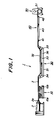
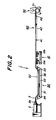
- Figs. 1 and 2 are side views showing different embodiments of the apparatus for reducing the posterior shrinkage amount of a rubber member according to the present invention.
- a vibrator device 10 for applying a vibration to an extruded rubber and a thermoregulator 30 for maintaining the extruded rubber at a controlled temperature are arranged on the downstream side of an extruder 2.
- the difference between these embodiments resides in the location of the vibrator device 10.
- the vibrator device 10 is arranged adjacent to the extruder 2 and the thermoregulator 30 is arranged on the downstream side of the vibrator device 10.
- the vibrator device 10 is arranged on the downstream side of the thermoregulator 30 which, in turn, is arranged adjacent to the extruder 2.
- the extrusion train 1 includes the extruder 2 on its upstream end, which serves to continuously extrude unvulcanized rubber 3 in the form of a strip, from an extrusion die 2a by driving an extrusion screw which is not shown.
- the rubber strip 3 immediately after the extrusion from the extruder 2 is typically at a temperature of 100-140°C and is then delivered to the vibrator device 10 on the downstream side.
- the vibrator device 10 may be comprised of a first vibrator unit 10a and a second vibrator unit 10b which may be of the same structure.
- first vibrator unit 10a As shown in Figs. 3 and 4, -the vibrator device 10 may be comprised of a first vibrator unit 10a and a second vibrator unit 10b which may be of the same structure.
- second vibrator unit 10b which may be of the same structure.
- the first vibrator unit 10a includes vertical frames 11 and a plurality of rollers 12 which are supported by the frames 11 and arranged at a predetermined pitch and in parallel with each other.
- Each roller 12 incorporates bearings therein and has a horizontal shaft 13 which is oriented so that the axis of the shaft 13 extends at right angle to the longitudinal direction of the extrusion train.
- the shaft 13 has both ends which are movably fitted in, and supported by vertical slots 14 at the upper ends of the respective frames 11. These slots 14 are spaced from each other at a predetermined pitch.
- twelve such rollers 12 are arranged at a pitch of 50mm.
- the vibrator unit 10a further includes a horizontal plate member 15 arranged below the rollers 12, having four corners which are connected to the upper ends of compression coil springs 17.
- the lower ends of the springs 17 are connected to a stationary base member 19 which is common to the two vibrator units 10a, 10b.
- the plate member 15 is provided with a center region having a lower surface which is in contact with the upper surface of a vibrator 16.
- the vibrator 16 has a lower portion which is fixedly secured to the base member 16.
- the vibrator 16 may be of a pneumatic-type, for example, and adapted to cause a vertical vibration of the plate member 15 with adjustable amplitude and/or frequency.
- a pair of elongate edge members 18 are fixedly provided for the plate member 15 on its both sides.
- Each edge member 18 is formed with semi-circular recesses 20 which are in contact with the lower surfaces of the relevant rollers 12. These recesses 20 are spaced from each other at a predetermined pitch. In the illustrated embodiment, twelve such recesses 20 are arranged at a pitch of 50mm.
- first vibrator unit 10a is comprised of the frame 11, rollers 12, shafts 13, slots 14, plate member 15, vibrator 16, coil springs 17, edge members 18, stationary frame 19, recesses 20, etc.
- the thermoregulator 30 on the downstream side of the vibrator device 10 includes a vessel 31 which is filled by a heat medium 32, such as appropriate gas or liquid.
- the heat medium 32 comprises water.
- the thermoregulator 30 is arranged such that the heat medium 32 is maintained at a controlled temperature, e.g., 10-100°C.
- a belt conveyor 33 is arranged within the vessel 31 and is comprised of a pair of pulleys 34, 35 and an endless belt 36 wound around and passed between the pulleys 34, 35.
- the pulley 35 is driven by a motor, not shown, so that the endless belt 36 is moved forward as shown by arrow and the extruded rubber strip 3 supported on the belt 36 is transferred toward the downstream side.
- thermoregulator 30 shown in Fig. 1 is arranged adjacent to the extruder 2, the extruded rubber strip 3 is cooled by the heat medium 32, typically to the room temperature, while it is transferred within the vessel 31 of the thermoregulator 30.
- the thermoregulator 30 is comprised of the vessel 31, heat medium 32, belt conveyor 33, pulleys 34, 35, endless belt 36, etc.
- a further conveyor 40 is arranged on the downstream side of the thermoregulator 30, and includes a pair of pulleys 41, 42 and an endless belt 43 wound around and passed between the pulleys 41, 42.
- the pulley 42 is driven by a motor, not shown, so that the endless belt 43 is moved forward as shown by arrow and the extruded rubber strip 3 supported on the belt 43 is transferred toward a movable trolley 50 which carries a winding drum thereon.
- the extruded rubber strip 3 which has been continuously supplied is cut into rubber member 51 having a predetermined length, e.g. a length corresponding to thirty tires, by a cutting device which is not shown. Subsequently, the rubber member 51 is wound around the drum on the trolley 50, and the trolley 50 is then moved to a subsequent station which is a green tire forming station.
- extrusion train 1 as a whole is comprised of the extruder 2 inclusive of the extrusion die 2a, as well as the vibrator device 10, thermoregulator 30, conveyor 40, trolley 50 and the winding drum, etc.
- the extruder 2 serves to continuously extrude a rubber strip 3 from the die 2a.
- the rubber strip 3 is fed toward the downstream side, with its lower surface maintaining contact with the surfaces of the rollers 12 of the vibrator device 10 comprised of two vibrator units 10a, 10b.
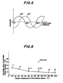
- the rubber strip 3 is placed under a vertical vibration at appropriate amplitude and frequency, by the vibrators 16 and via the respective rollers 12. By this, in a microscopic sense, the running rubber strip 3 assumes a sinusoidal shape with the lapse of time.
- the vibrator device 10 is comprised of two vibrator units 10a, 10b, it is possible to apply different vibrations to the extruded rubber strip 3, having an appropriate phase angle difference relative to each other.
- the waveform 10a' of the vibration excited by the first vibrator unit 10a and the waveform 10b' of the vibration excited by the second vibrator unit 10b may have a phase angle difference of 90°.
- Fig. 1 including a thermoregulator 30 which is arranged on the downstream side of the vibrator device 10, the extruded rubber applied with vibration is subjected to an accelerated cooling by the heat medium within the vessel 31.
- the extruded rubber strip 3 is transferred by the belt conveyor 33 within the vessel 31 and by a further conveyor 40 on the downstream side of the thermoregulator 30, is cut into a predetermined length and eventually wound around the winding drum on the trolley 50 as the rubber member 51 for use in the subsequent station.
- the application of vibrations to the extruded rubber 3 serves to increase the shrinkage speed of the extruded rubber 3 and cause a sufficient advance shrinkage of the extruded rubber within the extrusion train 1. Thus, it is possible to minimize the amount of posterior shrinkage of the rubber member 51.
- the extruded rubber strip 3 is applied with vibration after it has been placed under a controlled temperature by the heat medium within the vessel 31.
- the heat medium may be a warm water or gas.
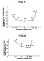
- the shrinkage ratio of the extruded rubber as the object of the experiments is determined in the following manner. That is, when the rubber strip 3 has been continuously extruded from the extruder 2, the entire upper surface of the rubber strip is applied with appropriate bench marks at a constant interval of 30cm. After the extruded rubber strip 3 has been passed through the various devices of the extrusion train 1, the rubber strip 3 is wound around the drum on the trolley 50 as the rubber member 51 and left for 24 hours to undergo a shrinkage. Then, the rubber member 51 is unwound from the drum to measure the distance between adjacent bench marks. The ratio between the initial interval between adjacent bench marks immediately after the extrusion, i.e., 30cm, and the distance between adjacent bench marks after the posterior shrinkage of the rubber member 51 is defined as the shrinkage ratio.
- the rubber member 51 obtained from an extruded rubber strip 3 which has not been subjected to vibration according to the prior art method has a shrinkage ratio which is as high as 40%.
- the rubber members 51 presubjected to vibration according to the examples 1-3 of the inventive method have shrinkage ratios reduced to 12-33%.
- the shrinkage ratio of the rubber member 51 according to the examples 1-3 exhibits an incremental tendency with increase in the frequency of the applied vibration. Such a tendency is believed primarily due to the fact that the amplitude of the applied vibration has been decreased with increase in the frequency.
- the present invention provides improved method and apparatus for reducing a posterior shrinkage amount of a rubber member which is comprised of a rubber extruded from an extruder, by applying vibration to the extruded rubber so as to increase the shrinkage speed of the extruded rubber and cause a sufficient advance shrinkage of the extruded rubber within the extrusion train, thereby reducing the posterior shrinkage amount of the rubber member.
- rollers 12 of the vibrator device 10 may be replaced by a number of balls arranged on the upper surface of the plate member 15.
- the second vibrator unit 10b may be replaced by a third unit in which a number of balls are arranged on the upper surface of the plate member 15.
- a plurality of first units and a plurality of third units may be arranged alternately to each other.
- each roller 12 may be associated with an individual vibrator 16 so that each roller 12 undergoes an independent vibration.
- the belt conveyor 33 of the thermoregulator 30 may be replaced by a number of rollers which are spaced from each other so that air can be discharged through gaps between adjacent rollers.
- the extruded rubber strip in the thermoregulator is placed under vibration by air bubbles.
Applications Claiming Priority (2)
| Application Number | Priority Date | Filing Date | Title |
|---|---|---|---|
| JP7049627A JPH08244090A (ja) | 1995-03-09 | 1995-03-09 | 押出しゴム部材の収縮量を緩和する方法及び装置 |
| JP49627/95 | 1995-03-09 |
Publications (2)
| Publication Number | Publication Date |
|---|---|
| EP0730939A2 true EP0730939A2 (de) | 1996-09-11 |
| EP0730939A3 EP0730939A3 (de) | 1997-05-21 |
Family
ID=12836470
Family Applications (1)
| Application Number | Title | Priority Date | Filing Date |
|---|---|---|---|
| EP96300657A Withdrawn EP0730939A3 (de) | 1995-03-09 | 1996-01-30 | Verfahren und Vorrichtung zur Reduzierung von Schrumpf in einem extrudierten Gummielement |
Country Status (3)
| Country | Link |
|---|---|
| US (1) | US5846475A (de) |
| EP (1) | EP0730939A3 (de) |
| JP (1) | JPH08244090A (de) |
Cited By (4)
| Publication number | Priority date | Publication date | Assignee | Title |
|---|---|---|---|---|
| WO1999038664A1 (en) * | 1998-01-29 | 1999-08-05 | The Goodyear Tire And Rubber Company | Extrudate shrinkage control and reduction |
| US6695606B1 (en) | 1998-01-29 | 2004-02-24 | The Goodyear Tire & Rubber Company | Extrudate shrinkage control and reduction |
| CN109664480A (zh) * | 2019-01-15 | 2019-04-23 | 宁夏神州轮胎有限公司 | 轮胎半成品低温冷却循环系统 |
| EP3643473A1 (de) * | 2018-10-25 | 2020-04-29 | Sumitomo Rubber Industries, Ltd. | Verfahren und vorrichtung zum formen einer unvernetzten elastomerkomponente |
Families Citing this family (7)
| Publication number | Priority date | Publication date | Assignee | Title |
|---|---|---|---|---|
| JP4786066B2 (ja) * | 2001-06-22 | 2011-10-05 | 東洋ゴム工業株式会社 | 帯状ゴム板冷却装置 |
| JP4425000B2 (ja) * | 2004-01-06 | 2010-03-03 | 株式会社ブリヂストン | ゴム部材搬送装置、及びそれを有するゴム部材供給システム |
| JP4149413B2 (ja) * | 2004-05-21 | 2008-09-10 | 日信工業株式会社 | 炭素繊維複合材料及びその製造方法 |
| DE602006005164D1 (de) * | 2005-07-13 | 2009-03-26 | Agfa Gevaert Nv | Verfahren zur breitschlitzextrusionsbeschichtung einer flüssigen zusammensetzung |
| JP5739691B2 (ja) * | 2011-03-02 | 2015-06-24 | 株式会社ブリヂストン | ゴム部材の冷却装置 |
| JP6784088B2 (ja) * | 2016-07-29 | 2020-11-11 | 住友ゴム工業株式会社 | 空気入りタイヤ製造方法 |
| JP7014020B2 (ja) * | 2018-04-09 | 2022-02-01 | 住友ゴム工業株式会社 | トレッドゴムの保管装置及び保管方法 |
Citations (3)
| Publication number | Priority date | Publication date | Assignee | Title |
|---|---|---|---|---|
| GB2117311A (en) * | 1982-02-16 | 1983-10-12 | Dunlop Ltd | Improvements in or relating to a method of and apparatus for extruding elastomeric components |
| JPS6487223A (en) * | 1987-09-29 | 1989-03-31 | Sakae Riken Kogyo Kk | Shrinkage prevention method and device for continuous extrusion molded product |
| JPH02235719A (ja) * | 1989-03-10 | 1990-09-18 | Toyoda Gosei Co Ltd | 発泡ゴム成形体の製造方法 |
Family Cites Families (5)
| Publication number | Priority date | Publication date | Assignee | Title |
|---|---|---|---|---|
| US4288398A (en) * | 1973-06-22 | 1981-09-08 | Lemelson Jerome H | Apparatus and method for controlling the internal structure of matter |
| US3285442A (en) * | 1964-05-18 | 1966-11-15 | Dow Chemical Co | Method for the extrusion of plastics |
| SU910459A1 (ru) * | 1980-07-16 | 1982-03-07 | Омский политехнический институт | Способ получени протектора |
| SU1426841A1 (ru) * | 1987-01-26 | 1988-09-30 | Воронежский шинный завод | Устройство дл изготовлени профилированных резиновых заготовок |
| JPH069845B2 (ja) * | 1988-11-24 | 1994-02-09 | 出光興産株式会社 | 押出成形方法とその装置 |
-
1995
- 1995-03-09 JP JP7049627A patent/JPH08244090A/ja active Pending
-
1996
- 1996-01-26 US US08/592,634 patent/US5846475A/en not_active Expired - Fee Related
- 1996-01-30 EP EP96300657A patent/EP0730939A3/de not_active Withdrawn
Patent Citations (3)
| Publication number | Priority date | Publication date | Assignee | Title |
|---|---|---|---|---|
| GB2117311A (en) * | 1982-02-16 | 1983-10-12 | Dunlop Ltd | Improvements in or relating to a method of and apparatus for extruding elastomeric components |
| JPS6487223A (en) * | 1987-09-29 | 1989-03-31 | Sakae Riken Kogyo Kk | Shrinkage prevention method and device for continuous extrusion molded product |
| JPH02235719A (ja) * | 1989-03-10 | 1990-09-18 | Toyoda Gosei Co Ltd | 発泡ゴム成形体の製造方法 |
Non-Patent Citations (4)
| Title |
|---|
| DATABASE WPI Week 8302 Derwent Publications Ltd., London, GB; AN 83-03900k XP002027604 & SU 910 459 A (OMSK POLY) , 7 March 1982 * |
| DATABASE WPI Week 8914 Derwent Publications Ltd., London, GB; AN 89-105296 XP002027603 & SU 1 426 841 A (VORON TYRE WKS ;VORON TECH INST) , 30 September 1988 * |
| PATENT ABSTRACTS OF JAPAN vol. 013, no. 296 (M-846), 10 July 1989 & JP 01 087223 A (SAKAE RIKEN KOGYO KK), 31 March 1989, * |
| PATENT ABSTRACTS OF JAPAN vol. 014, no. 552 (M-1056), 7 December 1990 & JP 02 235719 A (TOYODA GOSEI CO LTD), 18 September 1990, * |
Cited By (4)
| Publication number | Priority date | Publication date | Assignee | Title |
|---|---|---|---|---|
| WO1999038664A1 (en) * | 1998-01-29 | 1999-08-05 | The Goodyear Tire And Rubber Company | Extrudate shrinkage control and reduction |
| US6695606B1 (en) | 1998-01-29 | 2004-02-24 | The Goodyear Tire & Rubber Company | Extrudate shrinkage control and reduction |
| EP3643473A1 (de) * | 2018-10-25 | 2020-04-29 | Sumitomo Rubber Industries, Ltd. | Verfahren und vorrichtung zum formen einer unvernetzten elastomerkomponente |
| CN109664480A (zh) * | 2019-01-15 | 2019-04-23 | 宁夏神州轮胎有限公司 | 轮胎半成品低温冷却循环系统 |
Also Published As
| Publication number | Publication date |
|---|---|
| US5846475A (en) | 1998-12-08 |
| EP0730939A3 (de) | 1997-05-21 |
| JPH08244090A (ja) | 1996-09-24 |
Similar Documents
| Publication | Publication Date | Title |
|---|---|---|
| EP0730939A2 (de) | Verfahren und Vorrichtung zur Reduzierung von Schrumpf in einem extrudierten Gummielement | |
| US4586317A (en) | Minutely cross channeled voiding sealing systems | |
| US7438106B2 (en) | Production of shaped rubber body | |
| ES2073546T3 (es) | Metodo y aparato para estirar masa. | |
| US7794224B2 (en) | Apparatus for the continuous production of plastic composites | |
| KR102033709B1 (ko) | 벨트프레스식 플라스틱시트 제조장치 | |
| CN113276396B (zh) | 薄膜拉伸装置及其链夹动态定位方法 | |
| JPS6354334B2 (de) | ||
| KR20060121932A (ko) | 금속 빌렛의 가로형 주조장치 및 금속 빌렛의 절단방법 | |
| SU701542A3 (ru) | Способ непрерывного изготовлени листа полиметилметакрилата | |
| CN1251814C (zh) | 热轧薄带钢的方法 | |
| FI95023C (fi) | Laite mineraalikuitulevyjen valmistamiseksi | |
| US5792487A (en) | Corrugated plastic wall panels | |
| US4808358A (en) | Process to obtain molecular orientations in perforated plates made of extruded plastic material | |
| CN1089900A (zh) | 制造定向塑料带材的方法和装置 | |
| US5326508A (en) | Method for manufacturing semifinished products from a mixture of rubber and rubber-like plastic materials by shock cooling to increase tackiness | |
| US3011211A (en) | Elastomeric strip shrinking apparatus and method | |
| ES2116454T3 (es) | Mejoras en o relacionadas con los procedimientos y aparatos para la formacion continua de un producto extruido. | |
| US6098511A (en) | Method for cutting to length an unvulcanized rubber strip member by a cutting edge | |
| JP3187653B2 (ja) | 物品仕分けコンベヤ装置におけるスライドシュー | |
| US5158781A (en) | Traction apparatus for tubular material | |
| JP2854681B2 (ja) | 押出設備のストレッチャー | |
| CA1052960A (en) | Apparatus for curing elongate workpieces | |
| US4504004A (en) | Sheet forming machine | |
| US7033632B2 (en) | Casting food products to controlled dimensions |
Legal Events
| Date | Code | Title | Description |
|---|---|---|---|
| PUAI | Public reference made under article 153(3) epc to a published international application that has entered the european phase |
Free format text: ORIGINAL CODE: 0009012 |
|
| AK | Designated contracting states |
Kind code of ref document: A2 Designated state(s): DE ES FR IT |
|
| PUAL | Search report despatched |
Free format text: ORIGINAL CODE: 0009013 |
|
| AK | Designated contracting states |
Kind code of ref document: A3 Designated state(s): DE ES FR IT |
|
| 17P | Request for examination filed |
Effective date: 19971111 |
|
| 17Q | First examination report despatched |
Effective date: 19990715 |
|
| GRAG | Despatch of communication of intention to grant |
Free format text: ORIGINAL CODE: EPIDOS AGRA |
|
| STAA | Information on the status of an ep patent application or granted ep patent |
Free format text: STATUS: THE APPLICATION HAS BEEN WITHDRAWN |
|
| 18W | Application withdrawn |
Withdrawal date: 20020131 |