EP0728730B1 - Verfahren zur Herstellung von Monochloressigsäure - Google Patents
Verfahren zur Herstellung von Monochloressigsäure Download PDFInfo
- Publication number
- EP0728730B1 EP0728730B1 EP94119029A EP94119029A EP0728730B1 EP 0728730 B1 EP0728730 B1 EP 0728730B1 EP 94119029 A EP94119029 A EP 94119029A EP 94119029 A EP94119029 A EP 94119029A EP 0728730 B1 EP0728730 B1 EP 0728730B1
- Authority
- EP
- European Patent Office
- Prior art keywords
- mches
- catalyst
- dches
- hydrogenolysis
- blank
- Prior art date
- Legal status (The legal status is an assumption and is not a legal conclusion. Google has not performed a legal analysis and makes no representation as to the accuracy of the status listed.)
- Expired - Lifetime
Links
- FOCAUTSVDIKZOP-UHFFFAOYSA-N chloroacetic acid Chemical compound OC(=O)CCl FOCAUTSVDIKZOP-UHFFFAOYSA-N 0.000 title claims abstract description 14
- 238000004519 manufacturing process Methods 0.000 title description 4
- QTBSBXVTEAMEQO-UHFFFAOYSA-N Acetic acid Chemical compound CC(O)=O QTBSBXVTEAMEQO-UHFFFAOYSA-N 0.000 claims abstract description 69
- 238000007327 hydrogenolysis reaction Methods 0.000 claims abstract description 28
- 238000002425 crystallisation Methods 0.000 claims abstract description 27
- 230000003197 catalytic effect Effects 0.000 claims abstract description 9
- 238000000034 method Methods 0.000 claims description 58
- 239000003054 catalyst Substances 0.000 claims description 53
- KDLHZDBZIXYQEI-UHFFFAOYSA-N Palladium Chemical compound [Pd] KDLHZDBZIXYQEI-UHFFFAOYSA-N 0.000 claims description 32
- OKTJSMMVPCPJKN-UHFFFAOYSA-N Carbon Chemical compound [C] OKTJSMMVPCPJKN-UHFFFAOYSA-N 0.000 claims description 25
- 229910052763 palladium Inorganic materials 0.000 claims description 16
- 229910052799 carbon Inorganic materials 0.000 claims 1
- 238000005660 chlorination reaction Methods 0.000 abstract description 21
- 238000005119 centrifugation Methods 0.000 abstract description 4
- UFHFLCQGNIYNRP-UHFFFAOYSA-N Hydrogen Chemical compound [H][H] UFHFLCQGNIYNRP-UHFFFAOYSA-N 0.000 description 26
- 239000001257 hydrogen Substances 0.000 description 26
- 229910052739 hydrogen Inorganic materials 0.000 description 26
- 230000008025 crystallization Effects 0.000 description 24
- 238000006243 chemical reaction Methods 0.000 description 16
- 239000000047 product Substances 0.000 description 13
- JXTHNDFMNIQAHM-UHFFFAOYSA-N dichloroacetic acid Chemical group OC(=O)C(Cl)Cl JXTHNDFMNIQAHM-UHFFFAOYSA-N 0.000 description 10
- 239000012452 mother liquor Substances 0.000 description 8
- 239000011541 reaction mixture Substances 0.000 description 8
- 239000000460 chlorine Substances 0.000 description 7
- 238000004140 cleaning Methods 0.000 description 7
- 239000002994 raw material Substances 0.000 description 7
- WFDIJRYMOXRFFG-UHFFFAOYSA-N Acetic anhydride Chemical compound CC(=O)OC(C)=O WFDIJRYMOXRFFG-UHFFFAOYSA-N 0.000 description 6
- 238000010438 heat treatment Methods 0.000 description 6
- 239000000203 mixture Substances 0.000 description 6
- 229960005215 dichloroacetic acid Drugs 0.000 description 5
- 125000000896 monocarboxylic acid group Chemical group 0.000 description 5
- ZAMOUSCENKQFHK-UHFFFAOYSA-N Chlorine atom Chemical compound [Cl] ZAMOUSCENKQFHK-UHFFFAOYSA-N 0.000 description 4
- 229910052801 chlorine Inorganic materials 0.000 description 4
- 239000007789 gas Substances 0.000 description 4
- 238000005984 hydrogenation reaction Methods 0.000 description 4
- 239000007791 liquid phase Substances 0.000 description 4
- 239000002245 particle Substances 0.000 description 4
- 239000010409 thin film Substances 0.000 description 4
- 238000009825 accumulation Methods 0.000 description 3
- 238000002474 experimental method Methods 0.000 description 3
- 239000007788 liquid Substances 0.000 description 3
- 239000000725 suspension Substances 0.000 description 3
- 238000005299 abrasion Methods 0.000 description 2
- 239000006227 byproduct Substances 0.000 description 2
- 239000007795 chemical reaction product Substances 0.000 description 2
- 150000001875 compounds Chemical class 0.000 description 2
- 238000011109 contamination Methods 0.000 description 2
- 239000013078 crystal Substances 0.000 description 2
- 230000006378 damage Effects 0.000 description 2
- 238000009795 derivation Methods 0.000 description 2
- 238000010586 diagram Methods 0.000 description 2
- 230000008092 positive effect Effects 0.000 description 2
- 238000000746 purification Methods 0.000 description 2
- 238000000926 separation method Methods 0.000 description 2
- QSKPIOLLBIHNAC-UHFFFAOYSA-N 2-chloro-acetaldehyde Chemical compound ClCC=O QSKPIOLLBIHNAC-UHFFFAOYSA-N 0.000 description 1
- SZIFAVKTNFCBPC-UHFFFAOYSA-N 2-chloroethanol Chemical compound OCCCl SZIFAVKTNFCBPC-UHFFFAOYSA-N 0.000 description 1
- 229920002134 Carboxymethyl cellulose Polymers 0.000 description 1
- VGCXGMAHQTYDJK-UHFFFAOYSA-N Chloroacetyl chloride Chemical compound ClCC(Cl)=O VGCXGMAHQTYDJK-UHFFFAOYSA-N 0.000 description 1
- VYPSYNLAJGMNEJ-UHFFFAOYSA-N Silicium dioxide Chemical compound O=[Si]=O VYPSYNLAJGMNEJ-UHFFFAOYSA-N 0.000 description 1
- XSTXAVWGXDQKEL-UHFFFAOYSA-N Trichloroethylene Chemical group ClC=C(Cl)Cl XSTXAVWGXDQKEL-UHFFFAOYSA-N 0.000 description 1
- 238000004458 analytical method Methods 0.000 description 1
- 230000005587 bubbling Effects 0.000 description 1
- 239000001768 carboxy methyl cellulose Substances 0.000 description 1
- 235000010948 carboxy methyl cellulose Nutrition 0.000 description 1
- 239000008112 carboxymethyl-cellulose Substances 0.000 description 1
- 239000003153 chemical reaction reagent Substances 0.000 description 1
- 239000013065 commercial product Substances 0.000 description 1
- 238000001816 cooling Methods 0.000 description 1
- 238000006298 dechlorination reaction Methods 0.000 description 1
- 230000007812 deficiency Effects 0.000 description 1
- 239000003814 drug Substances 0.000 description 1
- 230000000694 effects Effects 0.000 description 1
- 230000002349 favourable effect Effects 0.000 description 1
- 239000010408 film Substances 0.000 description 1
- 230000036571 hydration Effects 0.000 description 1
- 238000006703 hydration reaction Methods 0.000 description 1
- 239000013067 intermediate product Substances 0.000 description 1
- 229910052751 metal Inorganic materials 0.000 description 1
- 239000002184 metal Substances 0.000 description 1
- 238000010327 methods by industry Methods 0.000 description 1
- 230000003647 oxidation Effects 0.000 description 1
- 238000007254 oxidation reaction Methods 0.000 description 1
- 239000000575 pesticide Substances 0.000 description 1
- 238000002360 preparation method Methods 0.000 description 1
- 239000003507 refrigerant Substances 0.000 description 1
- 229910052814 silicon oxide Inorganic materials 0.000 description 1
- 239000007790 solid phase Substances 0.000 description 1
- 239000000126 substance Substances 0.000 description 1
- 238000001356 surgical procedure Methods 0.000 description 1
- 239000012808 vapor phase Substances 0.000 description 1
- 239000002912 waste gas Substances 0.000 description 1
Images

Classifications
-
- C—CHEMISTRY; METALLURGY
- C07—ORGANIC CHEMISTRY
- C07C—ACYCLIC OR CARBOCYCLIC COMPOUNDS
- C07C51/00—Preparation of carboxylic acids or their salts, halides or anhydrides
- C07C51/347—Preparation of carboxylic acids or their salts, halides or anhydrides by reactions not involving formation of carboxyl groups
- C07C51/377—Preparation of carboxylic acids or their salts, halides or anhydrides by reactions not involving formation of carboxyl groups by splitting-off hydrogen or functional groups; by hydrogenolysis of functional groups
-
- C—CHEMISTRY; METALLURGY
- C07—ORGANIC CHEMISTRY
- C07C—ACYCLIC OR CARBOCYCLIC COMPOUNDS
- C07C51/00—Preparation of carboxylic acids or their salts, halides or anhydrides
- C07C51/42—Separation; Purification; Stabilisation; Use of additives
- C07C51/487—Separation; Purification; Stabilisation; Use of additives by treatment giving rise to chemical modification
Definitions
- the invention relates to the improvement of the (MCHES) monochloroacetic acid process and can be used in the chemical industry.
- MCHES is a valuable product for the production of carboxymethyl cellulose, various pesticides and pharmaceuticals.
- DE-A-18 16 931 contains a method for cleaning MCHES by means of Hydrogenation in the presence of a suspended, fine-grained catalyst based Silicon oxide or activated carbon.
- the catalyst is said to be in constant motion are held, with catalyst abrasion, resulting in its loss and leads to contamination of the reaction products.
- acetic anhydride is used as a catalyst in the chlorination of acetic acid.
- the reactions taking place in the process can be represented as follows: (CH 3 CO) 2 O + HCl -----> CH 3 COCl + CH 3 COOH CH 3 COCl + Cl 2 -----> CH 2 ClCOCl + HCl CH 2 ClCOCl + CH 3 COOH -----> CH 2 ClCOOH + CH 3 COCl etc.
- dichloroacetic acid (DCHES), which is formed during the chlorination of monochloroacetyl chloride: CH 2 ClCOCl + Cl 2 -----> CHCl 2 COCl + HCl CHCl 2 COCl + CH 3 COOH -----> CHCl 2 COOH + CH 3 COCl
- the continuous chlorination of acetic acid is carried out at 100 to 120 Degrees Celsius in the end product medium, which is 75 wt. % MCHES (Monochloroacetic acid), 18 wt. % Acetic acid and 7 wt. % Dichloroacetic acid contains.
- the chlorination product becomes the crystallization stage at 50 degrees Celsius fed.
- the crystallization is carried out when the product is cooled to 20 up to 25 degrees Celsius.
- a suspension of MCHES crystals is formed in a mixture with acetic acid and dichloroacetic acid.
- the suspension is then subjected to a separation, for example by means of Centrifugation.
- the solid phase is the commercial product, the liquid phase is sent to chlorination.
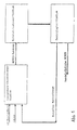
- Figure 1 shows the flow chart of the known monochloroacetic acid process shown.
- the aim of this invention is to reduce the raw material consumption index and increase performance in MCHES crystallization.
- the invention includes a process for the production of monochloroacetic acid (MCHES) by chlorination of acetic acid, an MCHES blank being produced and MCHES being separated from the blank by crystallization and centrifugation, characterized in that catalytic hydrogenolysis is carried out before crystallization, wherein this is carried out in an apparatus equipped with a gas lift (airlift) or on a fixed bed catalyst in thin-film operation.
- the hydrogenolysis process takes place in a fixed bed catalyst in thin-film operation at a feed speed of the MCHES blank between 0.049 and 1.24 m / s, in particular between 0.1 and 0.5 m / s.
- the goal is achieved by introducing a hydrogenolysis stage of MCHES blank after the chlorination stage and by forwarding the Product after the hydrogenation stage to the crystallization stage.
- FIG. 1 shows the flowchart of the proposed monochloroacetic acid process shown.
- the result achieved - consisting of a reduction in the consumption index after the raw material and increasing the performance of the crystallization stage - will ensured by the following: the introduction of the stage of catalytic Hydrogenolysis of the MCHES blank after the chlorination stage enables the reduction in the amount of DCHES in the blank of 7 wt. % to 1 to 1.5 wt. % and thus excludes the need to derive the mother liquor Annihilation from, that is, with the process the accumulation of DCHES locked out.
- FIG. 2 shows the block diagram of the proposed method for Preparation of monochloroacetic acid shown.
- the achievable result which in the reduction of the consumption values related to the raw material and in the Increased performance in the crystallization stage is ensured by Introduction of the subsequent stage of catalytic hydrogenolysis (substitutive hydrogenation) of the MCHES intermediate after the Chlorination level and allows the amount of DCHES to be reduced for the Intermediate level of 7 wt. % to 1 to 2.5 wt. %. Hence the need the derivation of the mother liquor for destruction is excluded. (In the block diagram the accumulation of DCHES is excluded.) The reduction of the DCHES content in the MCHES intermediate product is otherwise the same Conditions lead to an increase in performance in the crystallization stage. 0.5 to 2 wt. % Palladium used on activated carbon.
- a reactor in a reactor (column type) with a jacket is at a temperature of 110 Degrees Celsius in the liquid phase a catalytic (when adding Acetic anhydride 33.6 g / h) chlorination process of acetic acid gaseous chlorine performed.
- the chlorination process is at 10% Mole excess of chlorine carried out.
- the crystallization stage is a volumetric apparatus, in its mantle Refrigerant is supplied. In the crystallizers, this takes place in 12 hours Cooling of the MCHES blank from 50 to 20 degrees Celsius.
- the obtained one is conducted Centrifuge suspension. After that the quality and composition of the mother liquor and the amount and composition of the commercially available MCHES.
- the MCHES blank obtained during the chlorination is passed on to the catalytic hydrogenolysis stage.
- the consumption index for raw material and the yield of the target product is determined in the crystallization stage.
- the further object of this invention is to reduce catalyst consumption in the process of MCHES purification using hydrogenolysis and increasing the Process selectivity.
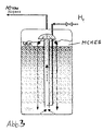
- the set goal is achieved by performing the hydrogenolysis process in an apparatus equipped with a gas lift (airlift).
- a gas lift By reducing the specific weight of the gas-liquid mixture this rises in the tube and tears the MCHES out of the Lower part of the reactor with.
- the Gas-liquid mixture This is the one that did not react Hydrogen is removed from the reactor with the waste gases, the MCHES is in the recycled upper reactor part.
- the positive effect consisting in the reduction of the catalyst consumption and the increase in selectivity is achieved by excluding the Hydrogen supply reached in the catalyst layer.
- An essential specific feature of the proposed procedure is - Carrying out the process using the airlift and feeding the total required hydrogen in this airlift.
- the Airlift is the hydrogen supply in the catalyst zone excluded what excludes catalyst wear and - consequently - to its consumption reduction and improvement of the finished product quality leads.
- the process selectivity is increased: a much smaller amount MCHES becomes acetic acid.
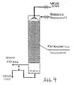
- the hydrogenolysis process can be carried out in a thin-layer operating mode in the apparatus with a fixed bed catalyst, and when the catalyst layer is sprinkled with an MCHES blank and hydrogen is fed into the upper part of the apparatus.
- the fictitious (arithmetical) feed speed for the MCHES blank must be 4.9 * 10 -2 -1.24 m / s.
- Figure 4 shows the process engineering scheme of the process.
- a positive effect in the proposed method, consisting in the Reduction of the catalyst consumption is achieved because of the implementation a process of cleaning the MCHES from admixtures of the DCHES (Dichloroacetic acid) in a thin-film mode of operation in the apparatus, the analog an attachment with filling compound is constructed; as a filling compound Palladium catalyst, for example 1% palladium on activated carbon used. This also favors the supply of hydrogen to the top of the apparatus. Such a supply of reagents excludes the possibility of one Catalyst particle movement and thus their rubbing and entrainment.
- the need to carry out the MCHES cleaning process at a fictitious feed speed of 4.9 * 10 -2 -1.24 m / s is that at a fictitious speed below 4.9 * -10 -2 m / s some catalyst parts of of the flowing MCHES thin layer are free, as a result of which an intensive vapor phase hydrogenolysis process of the MCHES to acetic acid runs on this catalyst part, that is to say the process selectivity is reduced.
- a vertical, cylindrical apparatus is loaded with 80 g of catalyst, which 1 wt. % Palladium on activated carbon and 332 g (210 ml) MCHES blank with 8.6 wt. % DCHES.
- catalyst which 1 wt. % Palladium on activated carbon and 332 g (210 ml) MCHES blank with 8.6 wt. % DCHES.
- hydrogen is supplied at a speed of 6 l / h. After 6 The hydrogen supply is interrupted for hours.
- DCHES content down to 1.18 wt. %
- the content of acetic acid (ES) is 2.8 wt. %
- the catalyst consumption was 1.5 g per 1 kg of reaction mixture.
- the concentrations of the DCHES and the acetic acid (ES) are lower than in the known method.
- the concentration of the DCHES is higher than with the known method; at a fictitious speed of less than 0.049 m / s, the concentration of acetic acid is higher than in the known method. Consequently, the aim of the invention in the part of increasing the process selectivity is achieved in the interval of feeding the MCHES blank of 4.9 * 10 -2 -1.24 m / s.
- An essential specific feature of the proposed (offered) MCHES cleaning process is the implementation of the hydrogenolysis process in a film mode of operation in the apparatus with a fixed bed catalyst, under the conditions of sprinkling the catalyst layer with MCHES blank and supplying hydrogen into the upper part of the apparatus.
- the fictitious (listed) feed speed for the MCHES blank must be 4.9 * 10 -2 -1.24 m / s.
- Feed speeds of 0.5 to 0.1 m / s can be regarded as particularly preferred, since both the DCHES content and the ES content assume favorable values.
- Chlorination stage example 1 Example 2 Supply of Cl 2 , g / h 331.76 331.76 Supply of ES (acetic acid) g / h 235.85 235.85 Obtained on MCHES blank, g / h 396.00 396.00 of it, g / h MCHES 297.00 297.00 DCHES 27.72 27.72 IT 71.28 71.28 Stage of hydrogenolysis Hydrogenolysis product, g / h 390.03 of it, g / h MCHES 313.35 DCHES 5.40 IT 71.28 Stage of crystallization Use for crystallization, g / operation 396.0 390.03 of it, g / operation MCHES 297.00 313.35 DCHES 27.72 5.40 IT 71.28 71.28 Won: Mother liquor
Landscapes
- Chemical & Material Sciences (AREA)
- Organic Chemistry (AREA)
- Chemical Kinetics & Catalysis (AREA)
- Engineering & Computer Science (AREA)
- Oil, Petroleum & Natural Gas (AREA)
- General Chemical & Material Sciences (AREA)
- Organic Low-Molecular-Weight Compounds And Preparation Thereof (AREA)
Description
Nach weiteren bevorzugten Merkmalen der Erfindung wird in der Hydrogenolyse ein Molverhältnis DCHES : H2 = 1 : 7 eingestellt, wobei die Hydrogenolyse bei Temperaturen zwischen 125 bis 140 °C durchgeführt wird.
Nach einem anderen bevorzugten Merkmal der Erfindung erfolgt der Hydrogenolyse-Prozeß in einem Festbett-Katalysator im Dünnschichtbetrieb bei einer Zufuhrgeschwindigkeit des MCHES-Rohlings zwischen 0,049 und 1,24 m/s, insbesondere zwischen 0,1 und 0,5 m/s.
| Chlorierungsstadium | Beispiel 1 | Beispiel 2 |
| Zuführung von Cl2, g/h | 331.76 | 331.76 |
| Zuführung von ES (Essigsäure) g/h | 235.85 | 235.85 |
| Gewonnen an MCHES-Rohling, g/h | 396.00 | 396.00 |
| davon, g/h | ||
| MCHES | 297.00 | 297.00 |
| DCHES | 27.72 | 27.72 |
| ES | 71.28 | 71.28 |
| Hydrogenolysestadium | ||
| Hydrogenolyseprodukt, g/h | 390.03 | |
| davon, g/h | ||
| MCHES | 313.35 | |
| DCHES | 5.40 | |
| ES | 71.28 | |
| Kristallisationsstadium | ||
| Einsatz zur Kristallisation, g/Operation | 396.0 | 390.03 |
| davon, g/Operation | ||
| MCHES | 297.00 | 313.35 |
| DCHES | 27.72 | 5.40 |
| ES | 71.28 | 71.28 |
| Gewonnen: | ||
| Mutterlauge, g/Operation | 196.00 | 149.24 |
| davon, g/Operation | ||
| MCHES | 99.00 | 74.56 |
| DCHES | 26.72 | 4.40 |
| ES | 70.28 | 70.28 |
| Handelsübliche MCHES, g/Operation | 200.00 | 240.79 |
| davon, g/Operation | ||
| MCHES | 198.00 | 238.39 |
| DCHES | 1.00 | 1.20 |
| ES | 1.00 | 1.20 |
| Verbrauchskennziffer | ||
| Tonnen je 1 Tonne MCHES | ||
| Essigsäure | 1.18 | 0.98 |
| Chlor | 1.66 | 1.38 |
| Kristallisationsleistung, g/Operation | 200.00 | 240.79 |
| Vers. Nr. | Durchm. cm | Fikt.Zufuhr- Geschw.für MCHES,m/s | Gehalt, gew. % | Verbrauch Katalysator g | |
| DCHES | ES | ||||
| Beispiel 1 | - | ||||
| Prototyp | - | - | 1,18 | 2,80 | 1,5 |
| Beispiel 2 | |||||
| 1. | 0,5 | 4,95 | 4,27 | 0,22 | 0,0 |
| 2. | 0,75 | 2,22 | 2,41 | 0,36 | 0,0 |
| 3. | 1,0 | 1,24 | 1,16 | 0,47 | 0,0 |
| 4. | 2,0 | 0,31 | 0,82 | 0,52 | 0,0 |
| 5. | 3,0 | 0,14 | 0,61 | 0,56 | 0,0 |
| 6. | 4,0 | 0,078 | 0,75 | 1,41 | 0,0 |
| 7. | 5,0 | 0,049 | 0,62 | 2,00 | 0,0 |
| 8. | 6,0 | 0,035 | 0,59 | 3,40 | 0,0 |
| 9. | 7,0 | 0,029 | 0,61 | 4,28 | 0,0 |
Claims (5)
- Verfahren zur Herstellung von Monochloressigsäure (MCHES) durch Chlorierung von Essigsäure, wobei ein MCHES-Rohling erzeugt wird und aus dem Rohling durch Kristallisation und Zentrifugierung MCHES agbetrennt wird, dadurch gekennzeichnet, daß
vor der Kristallisation eine katalytische Hydrogenolyse durchgeführt wird, wobei diese in einem mit Gasaufzug (Airlift) ausgestatteten Apparat oder an einem Festbettkatalysator im Dünnschichtbetrieb vorgenommen wird. - Verfahren nach Anspruch 1, dadurch gekennzeichnet, daß
in der Hydrogenolyse ein Molverhältnis DCHES : H2 = 1 : 7 eingestellt wird. - Verfahren nach Anspruch 2, dadurch gekennzeichnet, daß
als Katalysator Palladium auf Aktivkohle eingesetzt wird, insbesondere in einer Konzentration zwischen 0,5 und 2 gew. %. - Verfahren nach Anspruch 3, dadurch gekennzeichnet, daß
die Hydrogenolyse bei einer Temperatur zwischen 125 und 140 Grad Celsius durchgeführt wird. - Verfahren nach einem der Ansprüche 1 bis 4,
dadurch gekennzeichnet, daß
der Hydrogenolyse-Prozeß in einem Festbett-Katalysator im Dünnschichtbetrieb bei einer Zufuhrgeschwindigkeit des MCHES-Rohlings zwischen 0,049 und 1,24 m/s, insbesondere zwischen 0,1 und 0,5 m/s erfolgt.
Priority Applications (5)
| Application Number | Priority Date | Filing Date | Title |
|---|---|---|---|
| AT94119029T ATE199537T1 (de) | 1994-12-02 | 1994-12-02 | Verfahren zur herstellung von monochloressigsäure |
| DE59409675T DE59409675D1 (de) | 1994-12-02 | 1994-12-02 | Verfahren zur Herstellung von Monochloressigsäure |
| PT94119029T PT728730E (pt) | 1994-12-02 | 1994-12-02 | Processo de preparacao do acido monocloracetico |
| EP94119029A EP0728730B1 (de) | 1994-12-02 | 1994-12-02 | Verfahren zur Herstellung von Monochloressigsäure |
| ES94119029T ES2156134T3 (es) | 1994-12-02 | 1994-12-02 | Procedimiento para la obtencion de acido monocloracetico. |
Applications Claiming Priority (1)
| Application Number | Priority Date | Filing Date | Title |
|---|---|---|---|
| EP94119029A EP0728730B1 (de) | 1994-12-02 | 1994-12-02 | Verfahren zur Herstellung von Monochloressigsäure |
Publications (2)
| Publication Number | Publication Date |
|---|---|
| EP0728730A1 EP0728730A1 (de) | 1996-08-28 |
| EP0728730B1 true EP0728730B1 (de) | 2001-03-07 |
Family
ID=8216497
Family Applications (1)
| Application Number | Title | Priority Date | Filing Date |
|---|---|---|---|
| EP94119029A Expired - Lifetime EP0728730B1 (de) | 1994-12-02 | 1994-12-02 | Verfahren zur Herstellung von Monochloressigsäure |
Country Status (5)
| Country | Link |
|---|---|
| EP (1) | EP0728730B1 (de) |
| AT (1) | ATE199537T1 (de) |
| DE (1) | DE59409675D1 (de) |
| ES (1) | ES2156134T3 (de) |
| PT (1) | PT728730E (de) |
Families Citing this family (2)
| Publication number | Priority date | Publication date | Assignee | Title |
|---|---|---|---|---|
| CN105646190A (zh) | 2011-10-20 | 2016-06-08 | 阿克佐诺贝尔化学国际公司 | 将包含二氯乙酸的液体进料加氢脱氯的方法 |
| PL2748138T3 (pl) | 2011-10-20 | 2017-09-29 | Akzo Nobel Chemicals International B.V. | Proces oczyszczania ciekłego wsadu zawierającego mca i dca |
Family Cites Families (6)
| Publication number | Priority date | Publication date | Assignee | Title |
|---|---|---|---|---|
| US2863917A (en) | 1954-03-31 | 1958-12-09 | Hooker Chemical Corp | Method for reducing dichloroacetic acid in the presence of monochloro-acetic acid |
| SU104345A1 (ru) * | 1955-07-11 | 1955-11-30 | П.С. Копотун | Планировщик-волокуша |
| DE1201326B (de) * | 1963-12-21 | 1965-09-23 | Knapsack Ag | Verfahren zur partiellen Dehalogenierung von Di- und bzw. oder Trihalogenessigsaeure |
| DE1816931B2 (de) | 1968-12-24 | 1973-08-23 | Verfahren zur reinigung eines bei der chlorierung von essigsaeure unter bildung von monochloressigsaeure anfallenden rohproduktes | |
| FR2645531B1 (fr) * | 1989-04-07 | 1991-06-07 | Atochem | Procede et catalyseur de deshalogenation d'acides carboxyliques alphahalogenes |
| FR2682616B1 (fr) * | 1991-10-18 | 1993-12-10 | Atochem | Catalyseurs de deshalogenation d'acides carboxyliques alphahalogenes. |
-
1994
- 1994-12-02 ES ES94119029T patent/ES2156134T3/es not_active Expired - Lifetime
- 1994-12-02 PT PT94119029T patent/PT728730E/pt unknown
- 1994-12-02 DE DE59409675T patent/DE59409675D1/de not_active Expired - Fee Related
- 1994-12-02 EP EP94119029A patent/EP0728730B1/de not_active Expired - Lifetime
- 1994-12-02 AT AT94119029T patent/ATE199537T1/de not_active IP Right Cessation
Also Published As
| Publication number | Publication date |
|---|---|
| ES2156134T3 (es) | 2001-06-16 |
| PT728730E (pt) | 2001-08-30 |
| DE59409675D1 (de) | 2001-04-12 |
| EP0728730A1 (de) | 1996-08-28 |
| ATE199537T1 (de) | 2001-03-15 |
Similar Documents
| Publication | Publication Date | Title |
|---|---|---|
| DE3700132A1 (de) | Verfahren zum herstellen von ethylendichlorid | |
| DE4326952A1 (de) | Verfahren zur Herstellung von Triphenylphosphin | |
| DE69110590T2 (de) | Verfahren zur Herstellung von Anilin von hoher Reinheit. | |
| DE69101337T2 (de) | Verfahren zur Herstellung von Anilin hoher Reinheit. | |
| DE3881012T2 (de) | Verfahren zur Produktion von 4,4'-Diaminodicyclohexylmethan mit niedrigem trans-trans-Isomergehalt durch katalytische Hydrogenierung von 4,4'-Diaminodiphenylmethan. | |
| DE69515036T2 (de) | Verfahren zur herstellung von difluormethan | |
| DE69104644T2 (de) | Verfahren zur Dechlorierung von höheren Chloromethanen. | |
| DE2323777C2 (de) | Verfahren zur kontinuierlichen Reinigung von roher Monochloressigsäure | |
| DE19848668A1 (de) | Tetrachlorkohlenstoffarmes Phosgen | |
| EP0022751B1 (de) | Verfahren zur Herstellung von 2,6-Dialkylcyclohexylaminen | |
| EP0728730B1 (de) | Verfahren zur Herstellung von Monochloressigsäure | |
| DE69610406T2 (de) | Verfahren zur bildung zweier terminaler carboxylgruppen ausgehend von ozoniden | |
| DE69424899T2 (de) | Verfahren zur Herstellung von Essigsäure | |
| DE69509392T2 (de) | Reinigung von allylchlorid | |
| DE2513522A1 (de) | Verfahren zur herstellung von diacetoxybutan | |
| DE60111063T2 (de) | Verfahren zur herstellung von aromatischen aminen | |
| DE69008547T2 (de) | Verfahren zur Herstellung eines aromatischen Alkohols. | |
| DE1816931A1 (de) | Verfahren zur Reinigung technischer Monochloressigsaeure | |
| DE1074568B (de) | Verfahren zur Herstellung von Vinylchlorid oder Vinylidenchlorid 5 4 5ö V St Amerika | |
| DE19546080A1 (de) | Verfahren zur Darstellung einer besonders reinen Monochloressigsäure | |
| DE2723961C2 (de) | Verfahren zur Herstellung von 1,4-Glykoldiacetaten | |
| DE1568679B2 (de) | Verfahren zur Herstellung von 1,2-Dichloräthan | |
| DE2429293A1 (de) | Katalysatoren und ihre verwendung zur hydrierung | |
| DE3037047C2 (de) | ||
| EP0030269B1 (de) | Verfahren zur Rückführung des Edelmetallkatalysators bei der Herstellung aromatischer Urethane |
Legal Events
| Date | Code | Title | Description |
|---|---|---|---|
| PUAI | Public reference made under article 153(3) epc to a published international application that has entered the european phase |
Free format text: ORIGINAL CODE: 0009012 |
|
| AK | Designated contracting states |
Kind code of ref document: A1 Designated state(s): AT BE CH DE DK ES FR GB GR IE IT LI LU MC NL PT SE |
|
| AX | Request for extension of the european patent |
Free format text: SI PAYMENT 950120 |
|
| RAX | Requested extension states of the european patent have changed |
Free format text: SI PAYMENT 950120 |
|
| RAP1 | Party data changed (applicant data changed or rights of an application transferred) |
Owner name: SCIENTIFIC RESEARCH INSTITUTE SYNTEZ Owner name: SALZGITTER ANLAGENBAU GMBH |
|
| 17P | Request for examination filed |
Effective date: 19961209 |
|
| 17Q | First examination report despatched |
Effective date: 19970801 |
|
| GRAG | Despatch of communication of intention to grant |
Free format text: ORIGINAL CODE: EPIDOS AGRA |
|
| GRAG | Despatch of communication of intention to grant |
Free format text: ORIGINAL CODE: EPIDOS AGRA |
|
| GRAH | Despatch of communication of intention to grant a patent |
Free format text: ORIGINAL CODE: EPIDOS IGRA |
|
| GRAH | Despatch of communication of intention to grant a patent |
Free format text: ORIGINAL CODE: EPIDOS IGRA |
|
| GRAA | (expected) grant |
Free format text: ORIGINAL CODE: 0009210 |
|
| AK | Designated contracting states |
Kind code of ref document: B1 Designated state(s): AT BE CH DE DK ES FR GB GR IE IT LI LU MC NL PT SE |
|
| AX | Request for extension of the european patent |
Free format text: SI PAYMENT 19950120 |
|
| PG25 | Lapsed in a contracting state [announced via postgrant information from national office to epo] |
Ref country code: GR Free format text: LAPSE BECAUSE OF NON-PAYMENT OF DUE FEES Effective date: 20010307 |
|
| REF | Corresponds to: |
Ref document number: 199537 Country of ref document: AT Date of ref document: 20010315 Kind code of ref document: T |
|
| REG | Reference to a national code |
Ref country code: CH Ref legal event code: EP |
|
| REF | Corresponds to: |
Ref document number: 59409675 Country of ref document: DE Date of ref document: 20010412 |
|
| REG | Reference to a national code |
Ref country code: IE Ref legal event code: FG4D Free format text: GERMAN |
|
| GBT | Gb: translation of ep patent filed (gb section 77(6)(a)/1977) |
Effective date: 20010418 |
|
| ITF | It: translation for a ep patent filed | ||
| PG25 | Lapsed in a contracting state [announced via postgrant information from national office to epo] |
Ref country code: DK Free format text: LAPSE BECAUSE OF FAILURE TO SUBMIT A TRANSLATION OF THE DESCRIPTION OR TO PAY THE FEE WITHIN THE PRESCRIBED TIME-LIMIT Effective date: 20010607 |
|
| ET | Fr: translation filed | ||
| REG | Reference to a national code |
Ref country code: ES Ref legal event code: FG2A Ref document number: 2156134 Country of ref document: ES Kind code of ref document: T3 |
|
| PG25 | Lapsed in a contracting state [announced via postgrant information from national office to epo] |
Ref country code: MC Free format text: LAPSE BECAUSE OF NON-PAYMENT OF DUE FEES Effective date: 20011202 Ref country code: LU Free format text: LAPSE BECAUSE OF NON-PAYMENT OF DUE FEES Effective date: 20011202 Ref country code: AT Free format text: LAPSE BECAUSE OF NON-PAYMENT OF DUE FEES Effective date: 20011202 |
|
| PG25 | Lapsed in a contracting state [announced via postgrant information from national office to epo] |
Ref country code: LI Free format text: LAPSE BECAUSE OF NON-PAYMENT OF DUE FEES Effective date: 20011231 Ref country code: CH Free format text: LAPSE BECAUSE OF NON-PAYMENT OF DUE FEES Effective date: 20011231 |
|
| REG | Reference to a national code |
Ref country code: GB Ref legal event code: IF02 |
|
| PLBE | No opposition filed within time limit |
Free format text: ORIGINAL CODE: 0009261 |
|
| STAA | Information on the status of an ep patent application or granted ep patent |
Free format text: STATUS: NO OPPOSITION FILED WITHIN TIME LIMIT |
|
| 26N | No opposition filed | ||
| REG | Reference to a national code |
Ref country code: CH Ref legal event code: PL |
|
| PGFP | Annual fee paid to national office [announced via postgrant information from national office to epo] |
Ref country code: DE Payment date: 20021119 Year of fee payment: 9 |
|
| PGFP | Annual fee paid to national office [announced via postgrant information from national office to epo] |
Ref country code: FR Payment date: 20021209 Year of fee payment: 9 |
|
| PGFP | Annual fee paid to national office [announced via postgrant information from national office to epo] |
Ref country code: NL Payment date: 20021212 Year of fee payment: 9 Ref country code: GB Payment date: 20021212 Year of fee payment: 9 |
|
| PGFP | Annual fee paid to national office [announced via postgrant information from national office to epo] |
Ref country code: PT Payment date: 20021218 Year of fee payment: 9 Ref country code: BE Payment date: 20021218 Year of fee payment: 9 |
|
| PGFP | Annual fee paid to national office [announced via postgrant information from national office to epo] |
Ref country code: IE Payment date: 20021220 Year of fee payment: 9 |
|
| PGFP | Annual fee paid to national office [announced via postgrant information from national office to epo] |
Ref country code: SE Payment date: 20021230 Year of fee payment: 9 |
|
| PGFP | Annual fee paid to national office [announced via postgrant information from national office to epo] |
Ref country code: ES Payment date: 20030114 Year of fee payment: 9 |
|
| PG25 | Lapsed in a contracting state [announced via postgrant information from national office to epo] |
Ref country code: IE Free format text: LAPSE BECAUSE OF NON-PAYMENT OF DUE FEES Effective date: 20031202 Ref country code: GB Free format text: LAPSE BECAUSE OF NON-PAYMENT OF DUE FEES Effective date: 20031202 |
|
| PG25 | Lapsed in a contracting state [announced via postgrant information from national office to epo] |
Ref country code: SE Free format text: LAPSE BECAUSE OF NON-PAYMENT OF DUE FEES Effective date: 20031203 Ref country code: ES Free format text: LAPSE BECAUSE OF NON-PAYMENT OF DUE FEES Effective date: 20031203 |
|
| PG25 | Lapsed in a contracting state [announced via postgrant information from national office to epo] |
Ref country code: BE Free format text: LAPSE BECAUSE OF NON-PAYMENT OF DUE FEES Effective date: 20031231 |
|
| BERE | Be: lapsed |
Owner name: SCIENTIFIC RESEARCH INSTITUTE *SYNTEZ Effective date: 20031231 Owner name: *SALZGITTER ANLAGENBAU G.M.B.H. Effective date: 20031231 |
|
| PG25 | Lapsed in a contracting state [announced via postgrant information from national office to epo] |
Ref country code: PT Free format text: LAPSE BECAUSE OF NON-PAYMENT OF DUE FEES Effective date: 20040630 |
|
| PG25 | Lapsed in a contracting state [announced via postgrant information from national office to epo] |
Ref country code: NL Free format text: LAPSE BECAUSE OF NON-PAYMENT OF DUE FEES Effective date: 20040701 Ref country code: DE Free format text: LAPSE BECAUSE OF NON-PAYMENT OF DUE FEES Effective date: 20040701 |
|
| GBPC | Gb: european patent ceased through non-payment of renewal fee |
Effective date: 20031202 |
|
| EUG | Se: european patent has lapsed | ||
| PG25 | Lapsed in a contracting state [announced via postgrant information from national office to epo] |
Ref country code: FR Free format text: LAPSE BECAUSE OF NON-PAYMENT OF DUE FEES Effective date: 20040831 |
|
| NLV4 | Nl: lapsed or anulled due to non-payment of the annual fee |
Effective date: 20040701 |
|
| REG | Reference to a national code |
Ref country code: IE Ref legal event code: MM4A |
|
| REG | Reference to a national code |
Ref country code: FR Ref legal event code: ST |
|
| REG | Reference to a national code |
Ref country code: PT Ref legal event code: MM4A Free format text: LAPSE DUE TO NON-PAYMENT OF FEES Effective date: 20040630 |
|
| REG | Reference to a national code |
Ref country code: ES Ref legal event code: FD2A Effective date: 20031203 |
|
| PG25 | Lapsed in a contracting state [announced via postgrant information from national office to epo] |
Ref country code: IT Free format text: LAPSE BECAUSE OF NON-PAYMENT OF DUE FEES;WARNING: LAPSES OF ITALIAN PATENTS WITH EFFECTIVE DATE BEFORE 2007 MAY HAVE OCCURRED AT ANY TIME BEFORE 2007. THE CORRECT EFFECTIVE DATE MAY BE DIFFERENT FROM THE ONE RECORDED. Effective date: 20051202 |