EP0726860B1 - Verfahren und vorrichtung zum verbinden von karosserieteilen - Google Patents
Verfahren und vorrichtung zum verbinden von karosserieteilen Download PDFInfo
- Publication number
- EP0726860B1 EP0726860B1 EP95900175A EP95900175A EP0726860B1 EP 0726860 B1 EP0726860 B1 EP 0726860B1 EP 95900175 A EP95900175 A EP 95900175A EP 95900175 A EP95900175 A EP 95900175A EP 0726860 B1 EP0726860 B1 EP 0726860B1
- Authority
- EP
- European Patent Office
- Prior art keywords
- station
- support
- cassette
- assembly
- indexing
- Prior art date
- Legal status (The legal status is an assumption and is not a legal conclusion. Google has not performed a legal analysis and makes no representation as to the accuracy of the status listed.)
- Expired - Lifetime
Links
Images

Classifications
-
- B—PERFORMING OPERATIONS; TRANSPORTING
- B62—LAND VEHICLES FOR TRAVELLING OTHERWISE THAN ON RAILS
- B62D—MOTOR VEHICLES; TRAILERS
- B62D65/00—Designing, manufacturing, e.g. assembling, facilitating disassembly, or structurally modifying motor vehicles or trailers, not otherwise provided for
-
- B—PERFORMING OPERATIONS; TRANSPORTING
- B62—LAND VEHICLES FOR TRAVELLING OTHERWISE THAN ON RAILS
- B62D—MOTOR VEHICLES; TRAILERS
- B62D65/00—Designing, manufacturing, e.g. assembling, facilitating disassembly, or structurally modifying motor vehicles or trailers, not otherwise provided for
- B62D65/02—Joining sub-units or components to, or positioning sub-units or components with respect to, body shell or other sub-units or components
- B62D65/024—Positioning of sub-units or components with respect to body shell or other sub-units or components
- B62D65/026—Positioning of sub-units or components with respect to body shell or other sub-units or components by using a jig or the like; Positioning of the jig
-
- B—PERFORMING OPERATIONS; TRANSPORTING
- B23—MACHINE TOOLS; METAL-WORKING NOT OTHERWISE PROVIDED FOR
- B23K—SOLDERING OR UNSOLDERING; WELDING; CLADDING OR PLATING BY SOLDERING OR WELDING; CUTTING BY APPLYING HEAT LOCALLY, e.g. FLAME CUTTING; WORKING BY LASER BEAM
- B23K31/00—Processes relevant to this subclass, specially adapted for particular articles or purposes, but not covered by only one of the preceding main groups
- B23K31/02—Processes relevant to this subclass, specially adapted for particular articles or purposes, but not covered by only one of the preceding main groups relating to soldering or welding
-
- B—PERFORMING OPERATIONS; TRANSPORTING
- B23—MACHINE TOOLS; METAL-WORKING NOT OTHERWISE PROVIDED FOR
- B23K—SOLDERING OR UNSOLDERING; WELDING; CLADDING OR PLATING BY SOLDERING OR WELDING; CUTTING BY APPLYING HEAT LOCALLY, e.g. FLAME CUTTING; WORKING BY LASER BEAM
- B23K37/00—Auxiliary devices or processes, not specially adapted to a procedure covered by only one of the preceding main groups
- B23K37/04—Auxiliary devices or processes, not specially adapted to a procedure covered by only one of the preceding main groups for holding or positioning work
- B23K37/047—Auxiliary devices or processes, not specially adapted to a procedure covered by only one of the preceding main groups for holding or positioning work moving work to adjust its position between soldering, welding or cutting steps
-
- B—PERFORMING OPERATIONS; TRANSPORTING
- B62—LAND VEHICLES FOR TRAVELLING OTHERWISE THAN ON RAILS
- B62D—MOTOR VEHICLES; TRAILERS
- B62D65/00—Designing, manufacturing, e.g. assembling, facilitating disassembly, or structurally modifying motor vehicles or trailers, not otherwise provided for
- B62D65/02—Joining sub-units or components to, or positioning sub-units or components with respect to, body shell or other sub-units or components
-
- B—PERFORMING OPERATIONS; TRANSPORTING
- B23—MACHINE TOOLS; METAL-WORKING NOT OTHERWISE PROVIDED FOR
- B23K—SOLDERING OR UNSOLDERING; WELDING; CLADDING OR PLATING BY SOLDERING OR WELDING; CUTTING BY APPLYING HEAT LOCALLY, e.g. FLAME CUTTING; WORKING BY LASER BEAM
- B23K2101/00—Articles made by soldering, welding or cutting
- B23K2101/006—Vehicles
-
- Y—GENERAL TAGGING OF NEW TECHNOLOGICAL DEVELOPMENTS; GENERAL TAGGING OF CROSS-SECTIONAL TECHNOLOGIES SPANNING OVER SEVERAL SECTIONS OF THE IPC; TECHNICAL SUBJECTS COVERED BY FORMER USPC CROSS-REFERENCE ART COLLECTIONS [XRACs] AND DIGESTS
- Y10—TECHNICAL SUBJECTS COVERED BY FORMER USPC
- Y10T—TECHNICAL SUBJECTS COVERED BY FORMER US CLASSIFICATION
- Y10T29/00—Metal working
- Y10T29/49—Method of mechanical manufacture
- Y10T29/49826—Assembling or joining
- Y10T29/49828—Progressively advancing of work assembly station or assembled portion of work
- Y10T29/49829—Advancing work to successive stations [i.e., assembly line]
-
- Y—GENERAL TAGGING OF NEW TECHNOLOGICAL DEVELOPMENTS; GENERAL TAGGING OF CROSS-SECTIONAL TECHNOLOGIES SPANNING OVER SEVERAL SECTIONS OF THE IPC; TECHNICAL SUBJECTS COVERED BY FORMER USPC CROSS-REFERENCE ART COLLECTIONS [XRACs] AND DIGESTS
- Y10—TECHNICAL SUBJECTS COVERED BY FORMER USPC
- Y10T—TECHNICAL SUBJECTS COVERED BY FORMER US CLASSIFICATION
- Y10T29/00—Metal working
- Y10T29/49—Method of mechanical manufacture
- Y10T29/49826—Assembling or joining
- Y10T29/49895—Associating parts by use of aligning means [e.g., use of a drift pin or a "fixture"]
Definitions
- the present invention relates to a method and an assembly device for automobile body parts, in particular sheet metal elements, and more particularly the means allowing geometrical positioning, that is to say precise positioning and maintenance. parts in relation to each other, the assembly also being set up and held in a precise manner in a fixed reference point where the assembly tools move (welding robots, mechanized fixed or mobile welding tongs, bonding tools or glue, laser torch ).
- the first consists in bringing the parts to be assembled to an assembly station and securing them together using geometry tools.
- These tools belong to a station, for example along a general assembly line and their position is identified in a fixed reference system of the station in which the assembly tools also operate. It is then a specific machine or line that can only accept a single object model such as a car body.
- a base is brought to the station by means of a lower conveyor and then is separated from this conveyor by means of stops (stops, centering fingers, vertical supports, etc.) for referencing this base in the position reference.
- stops stops, centering fingers, vertical supports, etc.
- Other conveyors bring the body sides to the station where they are supported by mobile tools for placing these body sides in a position determined in the reference frame of the station, therefore relative to the base.
- other tools provide the roof, the crosspieces, ... in the same way.
- Such an assembly station allows only one geometry to be produced (monogeometry) with the advantage of reproducing exactly the same geometry for each product passing through it.
- This specificity of the machine has the disadvantage of not tolerating modifications to the model without heavy intervention on the tooling. Furthermore, it cannot be adapted to the mounting of more than one model in the same flow.
- Such a station can therefore accommodate pallets carrying different models because the tools it includes "see” only one and the same pallet face regardless of the model. Only the computer control relating to their course or their trajectory is to be changed from one model to another, which is infinitely faster than a modification of the tools.
- the alignment is generally carried out by locking the pallets to the fixed means of the work station.
- Such a technique is called multigeometry because even two identical products (the same vehicle model) are processed using separate pallets which are necessarily different due to the dispersions of ribs between the identical parts which make up these two pallets.
- two products of the same model do not necessarily have the same geometry, and the resulting manufacturing is of lower quality than a manufacturing of the monogeometry type.
- the invention makes it possible to satisfy this need by proposing a method and a mounting device which implements a light interface means which makes the part transparent with regard to its handling means, which makes it possible to standardize them and therefore to offer the manufacturer a greater choice, this interface means also carrying part of the means of the part intended to cooperate with means for geometry of the assembly station, which makes it possible to set up stations specific monogeometry type with the advantage of their better accuracy than in recyclable pallet stations, while promoting a certain standardization of the nature and location of the geometry means carried by the support of a model with l 'other.
- this method of assembling sheet metal parts by which at least two separate elements are brought into a geometry station, are immobilized by means of positioning tools belonging to the station in a determined relative position and in an overall position also determined in the reference of the post and are fixed to each other in particular by welding consists, according to the invention, in associating with at least one of the elements a support comprising means for gripping the element, means for its coupling to at least one handling device and means for its indexing in the coordinate system of the geometry station, to bring the element into the geometry station via this support, to carry out at least partial indexing of the element in the geometry station via the support, by actuating the positioning tools so that they cooperate in a shared manner with the element and with the support to achieve the final positioning of the element with if necessary, release of at most some of the gripping means and to proceed to the mutual connection of the elements.
- this process has the advantage of offering continuity for the successive stages of construction of an assembly of sheet metal parts.
- element is meant an elementary part and in this case the method is implemented in the assembly lines of subassemblies from the first station, the element "enriching" as and when its passage through successive positions to become a subset always associated with the basic support implemented from the outset.
- each element brought to the stations of the general assembly line could be a sub-assembly itself associated with a support having followed it throughout its assembly line upstream of the general assembly.
- This light support in accordance with the invention, moreover makes it possible to use handling means which are also light and therefore compact, which facilitates access to each station for the welding members or other assembly means.
- this support has the advantage of being storable in a small volume, in particular by vertical suspension.
- this support comprises a structure substantially contained between two surfaces, one of which comprises means for positioning in the referenced position and for holding the element and the other face of which includes some of the means for indexing the support / element set in the reference system of each station that receives it.
- This light structure presents itself both as a hand for gripping the elements to be assembled and as a mobile reference in which these elements are perfectly referenced.
- references (means which cooperate in the geometry of the product) which belong to the support need not be strictly and rigidly linked to each other by this support because they will be taken over by the means geometry of each station. It follows an important advantage of the invention, namely that the structure of the support being able to tolerate a certain elastic deformation, can be constructed like a light reinforcement whose deformations if they are of course contained within limits admissible have no influence on the geometry of the product because they are "corrected" at each station served by this support. In what follows, this support will also be called cassette.
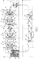
- a general conveyor 1 has been shown in a loop which circulates according to the arrows A on the one hand through seven stations 2 to 8 of a line for making a vehicle body sub-assembly for example a body side, and on the other hand along a general assembly line 1O in which, through several positions, the body side is joined to the other sub-assemblies of the body of a motor vehicle .
- Station 2 therefore comprises three stores 21, 22, 23 of the first part on this side of the body which is generally a piece of skin. It also includes a rack 24 which contains cassettes, an example of which is illustrated in FIG. 2, for each of the three models of body side to be produced.
- a handling member 25 represented here in the form of a robot makes it possible on the one hand to serve and serve the general handling device 1 and on the other hand to associate with each of the cassettes 24 the skin part of the models A, B, C corresponding by using the cassette as a hand for gripping the part to be grasped and extracted from the magazines 21, 22, 23.
- the cassette thus equipped with the first part and with respect to which this first part is referenced precisely by means which will be detailed with reference to the following figures, is transported to station 3.
- the cassette Unloaded from the general handling line 1 by means of one or other of the handling robots 31, 32, the cassette is, according to the model which it relates, placed in one of the stations 33 to 38 where the piece of skin which it carries is enriched with 'additional items.
- Each of the stations 33 to 38 is a geometry setting station which therefore has references for accommodating the cassette assembly plus piece of skin and for maintaining the elements that will be added to this piece of skin. A part of the references of each of these stations cooperates with the cassette while the other part cooperates with the piece of skin carried by the cassette.
- the manipulators 31, 32 cooperate only with the cassette associated with the product to serve and serve the handling line l and to set up the cassette-product assembly in the appropriate stations of station 3.
- the work being completed at station 3 the cassette is introduced to the next station 4 by the general handling line 1 where, as in the previous station, manipulators 41, 42 provide handling between line 1 and the various stations 43 to 48 of the station.
- Station 5 is a finishing station in which there is no geometry setting operation.
- additional welding, bonding, installation of intermediate fixing means are carried out, which only involve the part secured to the support.
- the sub-assembly carried by the cassette is taken over by a handling robot which brings it directly between the jaws of a welding gun fixed for example to the ground.
- Stations 6 and 7 are similar in all respects to stations 3 and 4 to enrich the subset body side of all the means it needs and for this purpose these stations have manipulators 61, 62, 71, 72 and geometry positioning stations 63 to 68 and 73 to 78.
- Station 8 is a finishing and final control station before the introduction of the cassette fitted with the body side sub-assembly completed in the general assembly line 1O.
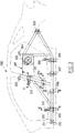
- a manipulator 111 makes it possible to introduce each of the cassettes equipped on the body side along, for example, the body base. You have to imagine the same installation on the other side of this general assembly line for the introduction of a second body side.
- Each station 12O, 13O and 14O of the general assembly line is for example dedicated to the assembly of one of the three vehicle models which constitute the manufacturing flow on this general assembly line.
- Other provisions can be adopted, such as having a single station and changing, depending on the model to be made on this station, the tools for geometry of this single station.
- the choice between these various solutions essentially depends on the similarity or the difference between the models which the general assembly line must accommodate.
- a manipulator 151 allows each of the cassettes to be recovered, the body side then being welded to the rest of the vehicle structure.
- This cassette is brought back by the handling line 1 to station 2 either to be stored in the rack 24, or to be immediately reused if the instantaneous demand for sides of boxes corresponds to the model that it is capable of accommodating.
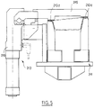
- the body side shown in phantom lines has the reference 2OO. It is essentially a sheet or a set of cut sheets stamped, one face of which, that visible in the figure, constitutes at least partially the skin of the vehicle, the opposite face of this sheet being equipped with a certain number of parts and accessories intended on the one hand for its assembly with the other parts of bodywork, and secondly to constitute means of connection or reception for elements such as interior trim, door hinges, lock strikes etc.
- the body side 2OO is equipped with a 2O1 cassette.
- This cassette is in fact a relatively light and airy structure comprised between two parallel surfaces which are also substantially parallel to the skin surface on the body side.
- the cassette 2O1 has a certain number of zones 2O2, 2O3, 2O4 which are equipped with means for receiving and connecting the cassette to a handling device.
- the zone 2O2 is constituted by a kind of plate which can be approached by the end of the wrist of a manipulator such as 25, 31, 41 ... and on which this manipulator can be locked.
- this zone 2O2 can carry information allowing the manipulator to recognize the type of cassette which he is docking and to take charge in order to be able to correctly direct the cassette to the appropriate station to receive it in each of the stations. 2 to 8.
- the zones 2O3 and 2O4 of the cassette simply comprise axes allowing its suspension, for example an overhead conveyor which could constitute the general handling line 1.
- the general shape of the 2O1 cassette is clearly understood dictated by the general shape of the sub-assembly which it must take care of as well as by the zones of this sub-assembly which, in the various stations of its construction and in the station of assembly, must constitute references to be set up precisely, that is to say to be directly in contact with the geometry setting tools.
- eight reference zones have been retained. These are the lower zones 205, 206, 207, 208 which are located opposite the flap on the body side, zone 209 opposite the upper part of the rear wheel arch, zones 210 and 211 opposite the middle leg on the body side and zone 22O to the right of the front part of the body side.
- the cassette has on its outer face a plate which constitutes a determined reference surface intended to cooperate with the referencing tools which are on standby or activated in the various stations of stations 3, 4, 6, 7 and in the general assembly line.
- the cassette On the other face, and in these areas 205 to 211 and 22O, the cassette also has reference surfaces for accommodating the body side 200 and for maintaining its geometry which is relatively deformable taking into account the fact that it acts mainly of stamped sheets.
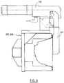
- Figure 3 there is shown the area 210 of the cassette with its plate 210 a and two arms 210 b , 210 c which are adapted on the one hand to master the shape of the middle leg and on the other hand to present end surfaces 210 d , 210 e for the support of this center leg, these end surfaces being perfectly defined with respect to the external surface of the plate 210 a .
- the body side is on the one hand pressed as in the other zones against a surface playing the same role as the surfaces 210 d and 210 e of FIG. 3, and on the other hand is supported vertically by a square slid at the high point of the wheel arch.
- This provision is not shown because one can imagine different ways of indexing the body side to the cassette. It is seen in the present case that for the zones 205 to 208, 210 and 211 the only precise reference is that which is taken in a direction perpendicular to the figure. With regard to zone 209, the reference has two components, the same as that of the preceding zones plus a vertical component since there is a support surface for the wheel arch.
- the means of indexing the body side on the cassette is constituted by a pilot (centering cylinder) 221 which is housed in an orifice in the bodywork (on the side of the cassette facing the body side) and which has a bore 222 which can itself accommodate a pilot from a station on the subassembly line and from a post on the general assembly line.
- the cassette also includes, on its face opposite to that visible in FIG. 2, means for holding preferably without clamping the body side against the cassette and in particular against the reference surfaces which it carries. These means are illustrated by FIGS. 5 and 6 and in FIG. 2 bear the references 212, 213 and 214.
- the means 213 comprises a jaw 215 movable relative to the surfaces 210 d and 210 e for supporting the center leg of the body, this jaw 215 being coupled to a jack 216 for operating its approximation or its spacing with respect to the plane of the surfaces 210 d , 210 e , the movement of the jaw can also be combined with a rotation around for example the axis of the jack 216, in order to completely release the center leg of the cassette.
- the fixing means 212 and 214 are of the same type as that 213 described above, namely comprising a jaw 217 and a jack 218, the jaw 217 now loosely clamping the flap against the Support surfaces identical to those 210 d , 210 e in line with zones 205 and 208.
- the entire cassette is inscribed inside the contour of the body side with which it is associated so that it leaves large areas on this side of the body cantilevered and perfectly accessible by means of geometry of a station either of the manufacturing line or of the general assembly line.
- the cantilevered zones consist of stretchers 220 on the body side, that is to say the high zones to be connected to the roof and to the front and rear crosspieces. It is indeed in this zone that the precision of the geometry of the bodywork must be the most important to avoid false squaring and appearance defects of the bodywork.
- the body side is connected by the lower flap to the underbody or floor of the vehicle.
- the cassette 201 has on its surface equipped with references in contact with the body side and at the level of the plate 202 for gripping by a robot, another plate which can be accessed through the door opening. behind the body side at this point.
- This plate includes coupling means identical to those of plate 202 for the wrist of a robot.
- This arrangement is entirely advantageous because it allows, by the simple choice of the gripping side of the cassette, to turn the sub-assembly which it carries in order to place it in a station, that is to say in a bump, that is to say the skin on the outside of the station, or in hollow, that is to say the skin against the references of the station.
- This possibility of overturning is advantageous because it simplifies certain operations of fitting and welding of the accessories which must equip the body side.
- the tools for geometry of the bodywork at the level of the stretchers 220 need to adjust the position of these stretchers to that of the sleeper flag or on the side of opposite body, a certain degree of freedom on the body side with respect to the floor.
- the jaws 217 of the means 212 and 214 which open the bottom flap against the cassette will be opened.
Claims (7)
- Verfahren zum Verbinden von Blechteilen, bei dem mindestens zwei separate Elemente einem Ausrichtstand zugeführt, mittels zum Stand gehörender Positioniervorrichtungen in einer vorbestimmten relativen Position und in einer ebenfalls vorbestimmten Baugruppenposition im Bezugssystem des Standes fixiert und insbesondere durch Schweißen miteinander verbunden werden, dadurch gekennzeichnet, daß das Verfahren umfaßt: das Verbinden mindestens eines der Elemente (200) mit einem Träger (201), der Mittel (212, 213, 214) zum Greifen des Elementes, Mittel (202, 203, 204) zum Koppeln mit mindestens einer Fördervorrichtung (1, 25, 31...) und Mittel (205, 211 und 220) zum Indexieren im Bezugssystem des Ausrichtstandes hat, das Zuführen des Elementes (200) zum Ausrichtstand mit Hilfe des Trägers (201), das anschließende zumindest teilweise Indexieren des Elementes am Ausrichtstand mit Hilfe des Trägers unter Betätigung der Positioniervorrichtungen, damit diese teilweise mit dem Element (200) und teilweise mit dem Träger zusammenwirken und so das endgültige Positionieren des Elementes erreicht wird, wobei gegebenenfalls höchstens einige (212, 214) der Greifmittel gelöst werden, sowie das anschließende gegenseitige Verbinden der Elemente.
- Verfahren nach Anspruch 1, dadurch gekennzeichnet, daß es außerhalb einer Hauptfertigungsstraße umfaßt: das Herausführen der die miteinander verbundenen Elemente (200) und den Träger (201) umfassenden Einheit aus dem Stand mittels einer Fördervorrichtung, die mit dem Träger zusammenwirkt, nachdem gegebenenfalls die Greifmittel des Trägers wieder zum Einsatz gebracht wurden.
- Verfahren nach Anspruch 1, das in einer Hauptfertigungsstraße (10) eingesetzt wird, dadurch gekennzeichnet, daß es umfaßt: das Lösen aller Greifelemente (212, 213, 214) des Trägers, um den Träger (201) vom Element (200) zu lösen.
- Verbindungsverfahren nach Anspruch 1, um nacheinander oder in beliebiger Reihenfolge verschiedenartige Teile oder Montagegruppen herzustellen, dadurch gekennzeichnet, daß es umfaßt: das Vorsehen ebensovieler verschiedener Arten von Trägern (201), wie es verschiedenartige Teile oder Montagegruppen (A, B, C) gibt, das Anordnen einer Vielzahl von Stationen (3, 4, 6, 7) mit Ständen (33 bis 38) entlang einer Hauptförderstraße (1), wobei die Anzahl der Stände in jeder Station gleich der Anzahl der verschiedenartigen Teile oder Montagegruppen ist, und wobei die Anzahl der Stationen von der Komplexität der zu realisierenden Montagegruppe abhängt, und das Beliefern eines jeden Standes einer jeden Station mittels einer Fördervorrichtung (31, 41), die mit der Vorrichtung zum Beliefern eines anderen Standes derselben Station identisch ausgebildet ist.
- Vorrichtung zum Durchführen des Verfahrens nach einem der vorhergehenden Ansprüche, dadurch gekennzeichnet, daß der Träger (201) eine mechanisch verschweißte Struktur umfaßt, deren Außenkontur so beschaffen ist, daß sie in das Innere eines der Struktur zugeordneten Elementes (200) einbeschrieben ist, wenn das Element eine Montagegruppe bildet, wobei die Struktur im wesentlichen von zwei Flächen begrenzt ist, von denen die eine Fläche Mittel (210c, 210d) zum Positionieren in vorbestimmter Lage und Mittel (215, 217) zum Halten des Elementes und die andere Fläche einige der Mittel (205-211) zum Indexieren der den Träger und das Element umfassenden Einheit im Bezugssystem des jeweiligen diese Einheit empfangenden Standes hat.
- Vorrichtung nach Anspruch 5, dadurch gekennzeichnet, daß der Träger (201) eine Vielzahl von Bereichen (202, 203, 204) hat, die Mittel zum Koppeln an eine Vielzahl verschiedenartiger Fördermittel haben.
- Verfahren nach Anspruch 6, dadurch gekennzeichnet, daß mindestens einer dieser Bereiche an der Fläche liegt, an der die Mittel (215, 217) zum Halten des Elementes angeordnet sind.
Applications Claiming Priority (3)
| Application Number | Priority Date | Filing Date | Title |
|---|---|---|---|
| FR9313062 | 1993-11-03 | ||
| FR9313062A FR2711957B1 (fr) | 1993-11-03 | 1993-11-03 | Procédé et dispositif d'assemblage pour pièces de carrosserie. |
| PCT/FR1994/001260 WO1995012515A1 (fr) | 1993-11-03 | 1994-10-28 | Procede et dispositif d'assemblage pour pieces de carrosserie |
Publications (2)
| Publication Number | Publication Date |
|---|---|
| EP0726860A1 EP0726860A1 (de) | 1996-08-21 |
| EP0726860B1 true EP0726860B1 (de) | 1997-03-12 |
Family
ID=9452458
Family Applications (1)
| Application Number | Title | Priority Date | Filing Date |
|---|---|---|---|
| EP95900175A Expired - Lifetime EP0726860B1 (de) | 1993-11-03 | 1994-10-28 | Verfahren und vorrichtung zum verbinden von karosserieteilen |
Country Status (10)
| Country | Link |
|---|---|
| US (1) | US6065200A (de) |
| EP (1) | EP0726860B1 (de) |
| KR (1) | KR960705713A (de) |
| CN (1) | CN1059633C (de) |
| BR (1) | BR9407966A (de) |
| CA (1) | CA2175821C (de) |
| DE (1) | DE69402086T2 (de) |
| ES (1) | ES2100765T3 (de) |
| FR (1) | FR2711957B1 (de) |
| WO (1) | WO1995012515A1 (de) |
Families Citing this family (38)
| Publication number | Priority date | Publication date | Assignee | Title |
|---|---|---|---|---|
| DE4418755A1 (de) * | 1994-05-28 | 1995-11-30 | Kuka Schweissanlagen & Roboter | Verfahren und Vorrichtung zum Zuführen, Spannen und Bearbeiten von Bauteilen einer Fahrzeugkarosserie |
| US6193142B1 (en) * | 1996-12-25 | 2001-02-27 | Nissan Motor Co., Ltd. | Assembling apparatus assembling body side of automotive vehicle and assembling method thereof |
| DE19734157A1 (de) * | 1997-08-07 | 1999-02-18 | Thyssen Industrie | Verfahren zum Anbringen der Türscharniere an Kfz-Karosserien und Vorrichtung zur Durchführung des Verfahrens |
| FR2777254B1 (fr) | 1998-04-10 | 2000-05-12 | Renault | Procede de fabrication de pieces de carrosseries de vehicules automobiles |
| JP3663984B2 (ja) * | 1999-08-06 | 2005-06-22 | 日産自動車株式会社 | 車体組立方法および車体組立装置 |
| US6435397B2 (en) * | 2000-04-18 | 2002-08-20 | Progressive Tool & Industries Co. | Robotic turntable |
| FR2810619B1 (fr) * | 2000-06-23 | 2003-01-17 | Renault | Procede et installation de montage d'organes mecaniques |
| US6457231B1 (en) * | 2000-09-07 | 2002-10-01 | Utica Enterprises, Inc. | Assembly line having transversely movable multiple part trays |
| KR100412650B1 (ko) * | 2001-07-11 | 2003-12-31 | 현대자동차주식회사 | 다차종 패널 파지장치 |
| US6807461B2 (en) * | 2002-05-22 | 2004-10-19 | Kuka Roboter Gmbh | Coordinated robot control from multiple remote instruction sources |
| US7100271B2 (en) * | 2003-09-23 | 2006-09-05 | Valiant Corporation | Automotive vehicle framing system |
| US7685699B2 (en) * | 2003-09-23 | 2010-03-30 | Variant Corporation | Docking apparatus |
| CN100390012C (zh) * | 2004-12-28 | 2008-05-28 | 株式会社本田阿克塞斯 | 车辆用部件定位用具 |
| US7727617B2 (en) | 2005-06-22 | 2010-06-01 | 3M Innovative Properties Company | Thermal mass transfer imaged retroreflective sheeting |
| JP4908861B2 (ja) * | 2006-02-01 | 2012-04-04 | 本田技研工業株式会社 | ワーク搬送装置 |
| US20080000068A1 (en) * | 2006-06-28 | 2008-01-03 | Savoy Mark A | Adjustment of work pallets for vehicle body assembly lines |
| PL1918182T3 (pl) | 2006-11-03 | 2009-06-30 | Comau Spa | Układ do montażu konstrukcji nadwozi pojazdów silnikowych lub ich podzespołów |
| US7964269B2 (en) | 2006-11-22 | 2011-06-21 | 3M Innovative Properties Company | Colorless thermal mass transfer compositions and articles |
| DE102007058432A1 (de) | 2007-12-05 | 2009-06-10 | Bayerische Motoren Werke Aktiengesellschaft | Typenvariable Fertigungsstraße |
| US8201723B2 (en) * | 2008-03-12 | 2012-06-19 | Comau, Inc. | Robotic high density welding body shop |
| KR20090105759A (ko) | 2008-04-03 | 2009-10-07 | 현대자동차주식회사 | 자동차용 플로워 생산시스템 |
| US8713780B2 (en) | 2008-05-13 | 2014-05-06 | Comau, Inc. | High density welding subassembly machine |
| DE102009006749A1 (de) * | 2009-01-30 | 2010-08-05 | Bayerische Motoren Werke Aktiengesellschaft | Fertigungssystem |
| CN103128537B (zh) * | 2011-11-24 | 2015-09-02 | 南车青岛四方机车车辆股份有限公司 | 轨道车辆车体组装柔性工艺装置 |
| CN103076182B (zh) * | 2011-12-30 | 2015-09-02 | 河北中兴汽车制造有限公司 | 一种汽车驾驶舱验证方法 |
| DE202014100850U1 (de) * | 2014-02-25 | 2015-05-28 | Kuka Systems Gmbh | Wechselvorrichtung |
| CN106103006B (zh) | 2014-03-06 | 2019-03-29 | 库卡系统有限责任公司 | 制造工作站,制造设备和方法 |
| DE202014101002U1 (de) | 2014-03-06 | 2015-06-12 | Kuka Systems Gmbh | Fertigungsstation |
| CN103879473B (zh) * | 2014-04-22 | 2016-08-24 | 北京汽车股份有限公司 | 一种汽车车身在线钻孔方法 |
| EP3233370B1 (de) | 2014-12-15 | 2018-09-12 | Comau LLC | System für modulare fahrzeugbaugruppe und verfahren |
| US10427740B2 (en) | 2015-10-21 | 2019-10-01 | Honda Motor Co., Ltd. | Split outer side panel jig and system |
| EP3452391B1 (de) | 2016-05-06 | 2024-01-10 | Comau LLC | Invertierter trägeraufzug |
| CN107458500B (zh) * | 2017-06-26 | 2019-06-21 | 北京长城华冠汽车科技股份有限公司 | 一种车身骨架的装配方法 |
| MX2020004708A (es) | 2017-11-07 | 2020-07-27 | Comau Llc | Sistema y metodos de transporte. |
| US11846932B2 (en) * | 2019-07-05 | 2023-12-19 | Industrial Technology Research Institute | Part processing planning method, part processing planning system using the same, part assembly planning method, part assembly planning system using the same, and computer program product thereof |
| US11420853B2 (en) | 2019-10-03 | 2022-08-23 | Comau Llc | Assembly material logistics system and methods |
| WO2021252329A1 (en) | 2020-06-08 | 2021-12-16 | Comau Llc | Assembly material logistics system and methods |
| CN112179673B (zh) * | 2020-09-17 | 2023-03-07 | 中国第一汽车股份有限公司 | 基于尺寸链分解的车门动态密封失效原因识别方法 |
Family Cites Families (15)
| Publication number | Priority date | Publication date | Assignee | Title |
|---|---|---|---|---|
| US4162387A (en) * | 1977-03-14 | 1979-07-24 | Ettore De Candia | Car body welding assembly system |
| US4316072A (en) * | 1979-09-17 | 1982-02-16 | Ductmate Industries, Inc. | Apparatus for positioning and securing components of a workpiece |
| US4295262A (en) * | 1980-03-21 | 1981-10-20 | Thermoplastics, Inc. | Method of making truck bed cover assembly |
| JPS6112474A (ja) * | 1984-06-26 | 1986-01-20 | Toyota Motor Corp | 車体組立装置 |
| GB2185220B (en) * | 1985-12-03 | 1989-04-05 | Honda Motor Co Ltd | Apparatus for assembling motor vehicle bodies |
| US4869416A (en) * | 1986-07-09 | 1989-09-26 | Mazda Motor Corporation | Assembly line conveyance |
| US5267385A (en) * | 1988-06-03 | 1993-12-07 | Honda Giken Kogyo Kabushiki Kaisha | Automatic assembly apparatus |
| US5044541A (en) * | 1989-04-21 | 1991-09-03 | Nissan Motor Co., Ltd. | Method and apparatus for assembling vehicle body |
| US5123161A (en) * | 1989-07-12 | 1992-06-23 | Honda Giken Kogyo Kabushiki Kaisha | Apparatus for setting car body components in motorcar body assembling line |
| IT1239855B (it) * | 1990-01-24 | 1993-11-15 | Fiat Auto Spa | Dispositivo per la saldatura di sottogruppi di scocche di autoveicoli costituiti da elementi di lamiera stampata. |
| JP2548040B2 (ja) * | 1990-02-15 | 1996-10-30 | 本田技研工業株式会社 | 車両用ドアの組付方法及び装置 |
| US5203811A (en) * | 1990-06-21 | 1993-04-20 | Mazda Motor Corporation | Method of positioning a door in an automobile body structure |
| US5265317A (en) * | 1991-12-19 | 1993-11-30 | Progressive Tool & Industries Co. | Geometry station |
| GB2273083B (en) * | 1992-12-01 | 1995-10-04 | Honda Motor Co Ltd | Apparatus for assembling motor vehicle body |
| IT1261269B (it) * | 1993-09-20 | 1996-05-09 | Comau Spa | Dispositivo per la saldatura a punti di strutture costituite da elementi di lamiera stampata, in particolare carrozzerie di autoveicoli |
-
1993
- 1993-11-03 FR FR9313062A patent/FR2711957B1/fr not_active Expired - Fee Related
-
1994
- 1994-10-28 ES ES95900175T patent/ES2100765T3/es not_active Expired - Lifetime
- 1994-10-28 DE DE69402086T patent/DE69402086T2/de not_active Expired - Fee Related
- 1994-10-28 CN CN94193995A patent/CN1059633C/zh not_active Expired - Fee Related
- 1994-10-28 BR BR9407966A patent/BR9407966A/pt not_active IP Right Cessation
- 1994-10-28 CA CA002175821A patent/CA2175821C/fr not_active Expired - Fee Related
- 1994-10-28 WO PCT/FR1994/001260 patent/WO1995012515A1/fr active IP Right Grant
- 1994-10-28 US US08/637,629 patent/US6065200A/en not_active Expired - Fee Related
- 1994-10-28 EP EP95900175A patent/EP0726860B1/de not_active Expired - Lifetime
- 1994-10-28 KR KR1019960702314A patent/KR960705713A/ko not_active Application Discontinuation
Also Published As
| Publication number | Publication date |
|---|---|
| DE69402086D1 (de) | 1997-04-17 |
| CA2175821C (fr) | 2005-01-11 |
| CA2175821A1 (fr) | 1995-05-11 |
| KR960705713A (ko) | 1996-11-08 |
| FR2711957B1 (fr) | 1996-01-05 |
| FR2711957A1 (fr) | 1995-05-12 |
| WO1995012515A1 (fr) | 1995-05-11 |
| ES2100765T3 (es) | 1997-06-16 |
| DE69402086T2 (de) | 1997-10-16 |
| US6065200A (en) | 2000-05-23 |
| CN1059633C (zh) | 2000-12-20 |
| EP0726860A1 (de) | 1996-08-21 |
| CN1134134A (zh) | 1996-10-23 |
| BR9407966A (pt) | 1996-12-03 |
Similar Documents
| Publication | Publication Date | Title |
|---|---|---|
| EP0726860B1 (de) | Verfahren und vorrichtung zum verbinden von karosserieteilen | |
| EP1084055B1 (de) | Herstellungsverfahren einer autokarosserie | |
| EP0800436B1 (de) | Montagewerkstatt für bleche | |
| EP2882568A1 (de) | Verfahren und vorrichtung zum schweissen von karosserieelementen eines kraftfahrzeugs mit schnellem werkzeugwechsel anhand eines hubrevolverkopfes | |
| EP2296960B1 (de) | System zur herstellung mindestens dreier arten einer motorfahrzeugkarosserie und verfahren zur durchführung dieser herstellung | |
| WO2008155474A1 (fr) | Outil de positionnement d'éléments hauts de carrosserie de véhicule sur une ligne d'assemblage, et son utilisation | |
| EP2129570B1 (de) | Geometrische konformationseinheit | |
| EP1220774B1 (de) | Haltevorrichtung zum halten eines teils hinsichtig eines zweiten teils | |
| FR2651699A1 (fr) | Installation de pliage des rebords d'une portiere de vehicule automobile. | |
| FR2715339A1 (fr) | Procédé et dispositif d'assemblage d'une carrosserie automobile. | |
| EP3283360B1 (de) | Montagestation für montage der karosserie eines kraftfahrzeugs | |
| FR2942157A1 (fr) | Dispositif de manutention concu pour une ligne d'emboutissage | |
| EP3800692B1 (de) | Befestigungsteil eines wechselrahmens für gabelstaplerbatterien | |
| EP1150879B1 (de) | Verfahren zur geometrischen verformung für kraftfahrzeugkarrosserien | |
| WO2008155475A1 (fr) | Outil de positionnement de jupes arrière de véhicule sur une ligne d'assemblage, et son utilisation | |
| FR3073437B1 (fr) | Station d’assemblage de caisse de vehicule automobile | |
| EP1057775B1 (de) | Anhängungsvorrichtung eines Kraftfahrzeugselementes an einem Fördermittel einer Fertigungsstrasse | |
| FR2714627A1 (fr) | Procédé d'assemblage de carrosserie de véhicule automobile. | |
| FR2635027A1 (fr) | Dispositif de positionnement de pieces a usiner | |
| JPH05261635A (ja) | 自動車ワーク組立方法及び組立用自走台車 | |
| WO2009007516A1 (fr) | Chassis mobile et calibre de conformation geometrique pour un outil de positionnement de pieces de toleries de vehicules automobiles, et utilisation de cet outil | |
| FR3070889B1 (fr) | Installation et procede d’assemblage d’une piece par soudage laser sur la caisse d’un vehicule | |
| WO2007048962A1 (fr) | Systeme et procede d'assemblage pour un vehicule | |
| FR3106123A1 (fr) | Palette modulable pour dispositif de transfert à accumulation de pièces de carrosserie de véhicule | |
| FR2906742A1 (fr) | Procede pour transporter et assembler des pieces et outils de support dans ce procede |
Legal Events
| Date | Code | Title | Description |
|---|---|---|---|
| PUAI | Public reference made under article 153(3) epc to a published international application that has entered the european phase |
Free format text: ORIGINAL CODE: 0009012 |
|
| GRAG | Despatch of communication of intention to grant |
Free format text: ORIGINAL CODE: EPIDOS AGRA |
|
| 17P | Request for examination filed |
Effective date: 19960425 |
|
| AK | Designated contracting states |
Kind code of ref document: A1 Designated state(s): BE DE ES FR GB IE IT PT SE |
|
| GRAH | Despatch of communication of intention to grant a patent |
Free format text: ORIGINAL CODE: EPIDOS IGRA |
|
| 17Q | First examination report despatched |
Effective date: 19960814 |
|
| GRAH | Despatch of communication of intention to grant a patent |
Free format text: ORIGINAL CODE: EPIDOS IGRA |
|
| GRAA | (expected) grant |
Free format text: ORIGINAL CODE: 0009210 |
|
| AK | Designated contracting states |
Kind code of ref document: B1 Designated state(s): BE DE ES FR GB IE IT PT SE |
|
| REF | Corresponds to: |
Ref document number: 69402086 Country of ref document: DE Date of ref document: 19970417 |
|
| REG | Reference to a national code |
Ref country code: IE Ref legal event code: FG4D Free format text: 72790 |
|
| GBT | Gb: translation of ep patent filed (gb section 77(6)(a)/1977) |
Effective date: 19970421 |
|
| ITF | It: translation for a ep patent filed |
Owner name: BARZANO' E ZANARDO MILANO S.P.A. |
|
| REG | Reference to a national code |
Ref country code: ES Ref legal event code: FG2A Ref document number: 2100765 Country of ref document: ES Kind code of ref document: T3 |
|
| PLBE | No opposition filed within time limit |
Free format text: ORIGINAL CODE: 0009261 |
|
| STAA | Information on the status of an ep patent application or granted ep patent |
Free format text: STATUS: NO OPPOSITION FILED WITHIN TIME LIMIT |
|
| 26N | No opposition filed | ||
| PGFP | Annual fee paid to national office [announced via postgrant information from national office to epo] |
Ref country code: IE Payment date: 20011016 Year of fee payment: 8 |
|
| REG | Reference to a national code |
Ref country code: GB Ref legal event code: IF02 |
|
| PG25 | Lapsed in a contracting state [announced via postgrant information from national office to epo] |
Ref country code: IE Free format text: LAPSE BECAUSE OF NON-PAYMENT OF DUE FEES Effective date: 20021028 |
|
| REG | Reference to a national code |
Ref country code: FR Ref legal event code: CJ Ref country code: FR Ref legal event code: CD Ref country code: FR Ref legal event code: CA |
|
| REG | Reference to a national code |
Ref country code: IE Ref legal event code: MM4A |
|
| PGFP | Annual fee paid to national office [announced via postgrant information from national office to epo] |
Ref country code: PT Payment date: 20061012 Year of fee payment: 13 |
|
| PGFP | Annual fee paid to national office [announced via postgrant information from national office to epo] |
Ref country code: ES Payment date: 20071010 Year of fee payment: 14 Ref country code: DE Payment date: 20071130 Year of fee payment: 14 |
|
| PGFP | Annual fee paid to national office [announced via postgrant information from national office to epo] |
Ref country code: IT Payment date: 20071015 Year of fee payment: 14 |
|
| PGFP | Annual fee paid to national office [announced via postgrant information from national office to epo] |
Ref country code: SE Payment date: 20071017 Year of fee payment: 14 Ref country code: BE Payment date: 20071119 Year of fee payment: 14 |
|
| PGFP | Annual fee paid to national office [announced via postgrant information from national office to epo] |
Ref country code: GB Payment date: 20071010 Year of fee payment: 14 Ref country code: FR Payment date: 20071011 Year of fee payment: 14 |
|
| REG | Reference to a national code |
Ref country code: PT Ref legal event code: MM4A Free format text: LAPSE DUE TO NON-PAYMENT OF FEES Effective date: 20080428 |
|
| PG25 | Lapsed in a contracting state [announced via postgrant information from national office to epo] |
Ref country code: PT Free format text: LAPSE BECAUSE OF NON-PAYMENT OF DUE FEES Effective date: 20080428 |
|
| BERE | Be: lapsed |
Owner name: *ABB PRECIFLEX SYSTEMS Effective date: 20081031 |
|
| EUG | Se: european patent has lapsed | ||
| GBPC | Gb: european patent ceased through non-payment of renewal fee |
Effective date: 20081028 |
|
| REG | Reference to a national code |
Ref country code: FR Ref legal event code: ST Effective date: 20090630 |
|
| PG25 | Lapsed in a contracting state [announced via postgrant information from national office to epo] |
Ref country code: IT Free format text: LAPSE BECAUSE OF NON-PAYMENT OF DUE FEES Effective date: 20081028 Ref country code: DE Free format text: LAPSE BECAUSE OF NON-PAYMENT OF DUE FEES Effective date: 20090501 |
|
| PG25 | Lapsed in a contracting state [announced via postgrant information from national office to epo] |
Ref country code: BE Free format text: LAPSE BECAUSE OF NON-PAYMENT OF DUE FEES Effective date: 20081031 |
|
| PG25 | Lapsed in a contracting state [announced via postgrant information from national office to epo] |
Ref country code: FR Free format text: LAPSE BECAUSE OF NON-PAYMENT OF DUE FEES Effective date: 20081031 |
|
| PG25 | Lapsed in a contracting state [announced via postgrant information from national office to epo] |
Ref country code: GB Free format text: LAPSE BECAUSE OF NON-PAYMENT OF DUE FEES Effective date: 20081028 |
|
| REG | Reference to a national code |
Ref country code: ES Ref legal event code: FD2A Effective date: 20081029 |
|
| PG25 | Lapsed in a contracting state [announced via postgrant information from national office to epo] |
Ref country code: ES Free format text: LAPSE BECAUSE OF NON-PAYMENT OF DUE FEES Effective date: 20081029 |
|
| PG25 | Lapsed in a contracting state [announced via postgrant information from national office to epo] |
Ref country code: SE Free format text: LAPSE BECAUSE OF NON-PAYMENT OF DUE FEES Effective date: 20081029 |