EP0726639A2 - Moteur pas à pas - Google Patents
Moteur pas à pas Download PDFInfo
- Publication number
- EP0726639A2 EP0726639A2 EP96101865A EP96101865A EP0726639A2 EP 0726639 A2 EP0726639 A2 EP 0726639A2 EP 96101865 A EP96101865 A EP 96101865A EP 96101865 A EP96101865 A EP 96101865A EP 0726639 A2 EP0726639 A2 EP 0726639A2
- Authority
- EP
- European Patent Office
- Prior art keywords
- stepper motor
- rotor
- motor according
- stator
- stators
- Prior art date
- Legal status (The legal status is an assumption and is not a legal conclusion. Google has not performed a legal analysis and makes no representation as to the accuracy of the status listed.)
- Granted
Links
Images


Classifications
-
- H—ELECTRICITY
- H02—GENERATION; CONVERSION OR DISTRIBUTION OF ELECTRIC POWER
- H02K—DYNAMO-ELECTRIC MACHINES
- H02K7/00—Arrangements for handling mechanical energy structurally associated with dynamo-electric machines, e.g. structural association with mechanical driving motors or auxiliary dynamo-electric machines
- H02K7/10—Structural association with clutches, brakes, gears, pulleys or mechanical starters
- H02K7/116—Structural association with clutches, brakes, gears, pulleys or mechanical starters with gears
-
- G—PHYSICS
- G01—MEASURING; TESTING
- G01R—MEASURING ELECTRIC VARIABLES; MEASURING MAGNETIC VARIABLES
- G01R7/00—Instruments capable of converting two or more currents or voltages into a single mechanical displacement
- G01R7/04—Instruments capable of converting two or more currents or voltages into a single mechanical displacement for forming a quotient
- G01R7/06—Instruments capable of converting two or more currents or voltages into a single mechanical displacement for forming a quotient moving-iron type
-
- H—ELECTRICITY
- H02—GENERATION; CONVERSION OR DISTRIBUTION OF ELECTRIC POWER
- H02K—DYNAMO-ELECTRIC MACHINES
- H02K37/00—Motors with rotor rotating step by step and without interrupter or commutator driven by the rotor, e.g. stepping motors
- H02K37/10—Motors with rotor rotating step by step and without interrupter or commutator driven by the rotor, e.g. stepping motors of permanent magnet type
- H02K37/12—Motors with rotor rotating step by step and without interrupter or commutator driven by the rotor, e.g. stepping motors of permanent magnet type with stationary armatures and rotating magnets
- H02K37/14—Motors with rotor rotating step by step and without interrupter or commutator driven by the rotor, e.g. stepping motors of permanent magnet type with stationary armatures and rotating magnets with magnets rotating within the armatures
Definitions
- the invention relates to a stepper motor according to the preamble of claim 1.
- stepper motors have gained great importance in recent years, for example in automotive engineering, and are used for the analog display of driving conditions and driver information, with digital measured values, such as speed, engine speed, fuel level, oil pressure, etc., being displayed in high resolution.
- the individual steps must be chosen so small that the viewer can no longer perceive them as such, but is given the impression of a continuous analog display.
- Reduction gears with a reduction ratio of 60: 1 are usually used, which, in conjunction with conventional step angles, allow sufficient resolution.
- stepper motor has a simple and robust design and is therefore inexpensive to manufacture.
- a stepper motor has become known, for example, from DE 42 07 978, which has two stators arranged one above the other and offset at an angle to one another.
- the stators are ring-shaped and completely surround the rotor provided with a permanent magnet in the circumferential direction.
- the assembly of the entire stepper motor is comparatively simple since all components are successively inserted in one housing.
- Correspondingly coordinated positioning elements ensure that all components can only be inserted in the specified assignment. This applies in particular to the stators, which must have the intended angular offset.
- the disadvantage here is the comparatively high effort that is required on the housing and the stators in order to form the positioning elements.
- the structure of the two stators in particular is comparatively complex since the stator laminations have to be specially shaped because of the ring shape of the coils.
- the coaxial arrangement of the two annular stators also leads to a relatively large overall height of the stepper motor, which is undesirable for a number of applications. In this type of arrangement, high axial forces also occur, which lead to an axial deflection of the rotor (so-called jumping).
- the invention was therefore based on the problem of providing a stepper motor of the type mentioned at the outset which no longer has the disadvantages described.
- a simple stepper motor should be implemented, which has a particularly flat design enables.
- the invention is based on the idea of designing the stator sheets flat and in a U-shaped basic shape, so that two parallel legs are formed.
- the opposite leg ends form a pair of poles and enclose the rotor along two circumferential sections.
- segment-shaped recesses are provided on the legs.
- Two such stator laminations can be arranged at 90 ° to each other, for example, so that a four-pole arrangement results in the region of the leg ends lying one above the other.
- the circular segment-shaped recesses of the leg ends form (in plan view) a circular opening through which the rotor passes through with a comparatively small radial distance.
- stator plates allow an extremely flat design of the stepper motor.
- the two stator laminations can thus be arranged closely one above the other, this distance being less than the thickness of the stator laminations themselves, which therefore no longer represent the limiting factor for the smallest possible height of the stepper motor.
- this type of arrangement has the advantage that the axial forces that occur are small and the jumping of the rotor explained at the outset is practically eliminated is.
- the stepper motor Due to this special design and arrangement of the stator plates, the stepper motor has an excellent efficiency, i. H. it generates high torque with low power consumption. Due to the flat design, the axial extent of the rotor is smaller than in conventional stepper motors, so that the efficiency is further improved.
- the flat design also permits extremely cost-effective production of the stator sheets, for example in the form of one-piece stamped parts which do not require any further processing.
- stator laminations to be congruent and used in mirror image. As a result, only a single type of stator sheet is required.
- the magnetic flux is generated by coils, which are each advantageously pushed over one of the two legs of the stator sheets and locked there. Due to the U-shape of the stator laminations, the coils can be easily guided over the respective end of the leg and moved into the vicinity of the web connecting the two legs. It is also possible to use coils of identical design for both stator laminations, so that here too, only a single coil type is required.
- the stepper motor advantageously has a two-part housing with a lower housing part and a cover placed thereon, the lower housing part being designed in such a way that all components, in particular the stators, the rotor and the reduction gear which may be present, can be accommodated in a positioning manner.
- the lower housing part is designed in such a way that all components, in particular the stators, the rotor and the reduction gear which may be present, can be accommodated in a positioning manner.
- pegs, peg receptacles, locking elements and the like formed on the lower housing part, so that the components can be simply inserted and plugged in when the stepping motor is assembled.
- the cover is designed so that all components are fixed after locking with the lower housing part.
- the cover has peg-like projections, abutments and peg receptacles, so that after locking with the lower housing part all components are fixed and / or movably mounted.
- the stepper motor can be manufactured extremely cost-effectively by simply plugging one into the other without additional fixing means, such as screws or rivets.
- additional fixing means such as screws or rivets.
- extremely simple disassembly for example to recycle the stepper motor at the end of its useful life.
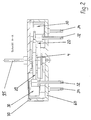
- stepper motor shown in FIGS. 1 to 4. It is a two-phase stepper motor with four poles, in which the pole pairs are arranged with alternating poles.
- the stepper motor is made up of a few main assemblies, namely two stators 2, a rotor 4 and a reduction gear 8, which are accommodated in a housing 6, consisting of lower housing part 60 and cover 70.
- Each of the two stators 2 has a stator plate 20 which is flat and U-shaped.
- Each of the two stator laminations 20 has two legs 22, 25 which run essentially parallel and which are shaped via a web 21 to form a one-piece and continuous U.
- In the end region of the legs 22, 25 there are recesses 23, 26 in the form of segments of a circle, so that the rotor 4 passed through at this point is contour-matched and encompasses radial clearance along two opposite circumferential sections.
- fastening holes 24, 27 which, together with a fastening hole 29 provided in the region of the web 21, enable the stator plate 20 to be fixed in three points.
- the leg 25 has a cutout 28 in order to allow a space-saving arrangement of a transmission wheel 80 of the reduction gear 8.
- a coil 30 is pushed over the leg 22 and locked in a manner not shown here.
- the coil 30 carries a winding 35 which is accessible from the outside via connecting pins 32, 34 and is held between two cover disks 31, 33.
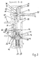
- Both stator plates 20 are congruent and are arranged mirror-symmetrically with respect to the section line B-B according to FIG.
- the angle between the two stator sheets 20 is 90 °, so that two pole pairs are formed in the area of the rotor 4.
- the recesses 23, 26 each represent these pole pairs, which surround the rotor 4 in a uniform angular arrangement.
- the two stator sheets 20 are arranged close to one another, as can be seen, for example, from FIGS. 2 or 3.
- the (axial) distance between the two stator sheets 20 is only a fraction of the thickness of the stator plates 20, so that the stepper motor is very flat overall.
- the distance between the two stator sheets 20 is selected so that contact between the two stator sheets 20 is reliably avoided even under extreme operating conditions, but is otherwise as small as possible.
- the rotor 4 has a permanent magnet 41 made of plastic-bonded magnetic material. In each case two poles are angularly offset from one another by 180 ° and spaced coaxially, as can be seen in FIG. 5b. This arrangement ensures that each stator plate 20 is assigned a pair of poles of the rotor 4. This means that axial forces no longer occur and the rotor is prevented from jumping.
- the permanent magnet 41 is mounted on a rotor shaft 42 (cf. FIG. 3) which also carries a drive pinion 46.
- the rotor shaft 42 merges in one piece at both ends into bearing journals 43, 44 which are inserted into correspondingly shaped journal receptacles 65, 75.
- the rotor 4 is thus fixed in the axial direction between the lower housing part 60 and the cover 70, but is rotatably mounted.
- the rotary movement of the rotor 4 is transmitted to an output shaft 95 via the reduction gear 8.
- the output shaft 95 represents, for example, the pointer shaft of a tachometer.
- the reduction gear 8 has a reduction ratio of 60: 1, so that the desired resolution is achieved within an intended swivel range of the pointer (for example 300 °).
- two transmission wheels 80, 85 are provided, which are connected between the drive pinion 46 of the rotor 4 and an output wheel 90 carrying the output shaft 95.
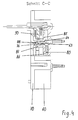
- the transmission wheel 80 has a toothing 81 which meshes with the drive pinion 46, as well as a further toothing 82 which is in engagement with the next transmission wheel 85 (FIG. 3).
- the transmission wheel 85 has a first toothing 86 and a further toothing 87 which is in engagement with a toothing 91 of the driven wheel 90.
- the arrangement of the transmission wheels 80, 81 and the driven gear 90 is selected so that the space in the lower part of the housing that is available between the two stators 20 is optimally used.
- the stator plates 20 are therefore each provided with the cutout 28 into which the transmission wheel 80 with its axial section carrying the toothing 82 can protrude.
- a support pin 74 arranged on the cover 70 can be passed from above and secures the end face of the transmission wheel 80 in a coaxial orientation.
- the transmission wheel 80 is held by a shoulder-like projection on a bearing journal 66 which is integrally formed on the lower housing part 60.
- the bearing journal 66 is precisely matched to a bearing bore 83 passing through the transmission wheel 80, so that no further bearing elements are required and simple assembly is made possible by plugging the transmission wheel 80 onto the bearing journal 66.
- the transmission wheel 85 (see FIG. 4) is mounted in a similar manner. It has a bearing bore 88 which is precisely matched to a bearing pin 63.
- the bearing pin 63 is integrally formed on the lower housing part 60 and carries a shoulder 64, which represents an axial stop for the transmission wheel 85 towards the lower housing part 60.
- On the cover side is again a support pin 76 is provided which serves as an axial securing means.
- the driven gear 90 is mounted in the lower housing part 60 via the output shaft 95, which engages in a pin receptacle 68 of the lower housing part 60. Furthermore, the driven wheel 90 has an integrally formed shoulder 92 which is directed towards the inside of the cover. Opposite is a bushing 72 for the output shaft 95 in the cover 70. The bushing 72 is designed to be flared towards the inside of the housing 6 in order to facilitate the passage of the driven shaft 95 during assembly.
- the stepper motor can be assembled by simply plugging the components together. No special positioning aids are required here, since these are already formed on the lower housing part 60, for example in the form of the bearing pins 63, 66 or the pin receptacles 65, 68. To fix the components used, it is only necessary to place the cover 70 on the lower housing part 60 and to latch it. Due to the positioning and fixing elements realized in the form of the support pins 74, 76 and pin receptacle 75, the stepping motor is ready for use after assembly. In order to lock the cover 70, four locking lugs 62 are formed on the lower housing part 60. Furthermore, the lower housing part 60 has two fastening eyes 61 with which the stepper motor can be fastened at the installation site.
- a tooth play compensation is provided. This is realized by a spiral spring 98, which on the one hand on the output shaft 95 and on the other hand via a fixing element 97 molded on the housing lower part 60 bracket 69.
- a brake spring 99 can be provided, as shown in FIGS. 5 and 5a.
- the brake spring 99 essentially consists of an elastically deformable strip, for example a spring steel strip, which rests on the shoulder 92 of the driven wheel 90 and is pressed in the direction of the lower housing part 60 by an abutment 73 formed on the cover 70. As a result, the desired braking effect is achieved due to friction between the shoulder 92 and the brake spring 99.
- the embodiment variant shown in FIG. 5a has the brake spring 99 instead of the tooth play compensation or spiral spring 98, whereas the embodiment according to FIG. 5 has both spiral spring 98 and brake spring 99.
Landscapes
- Engineering & Computer Science (AREA)
- Power Engineering (AREA)
- Physics & Mathematics (AREA)
- General Physics & Mathematics (AREA)
- Connection Of Motors, Electrical Generators, Mechanical Devices, And The Like (AREA)
- Electromechanical Clocks (AREA)
- Control Of Stepping Motors (AREA)
- Valve Device For Special Equipments (AREA)
- Adjustment Of Camera Lenses (AREA)
- Lens Barrels (AREA)
- Windings For Motors And Generators (AREA)
- Iron Core Of Rotating Electric Machines (AREA)
- Permanent Magnet Type Synchronous Machine (AREA)
Applications Claiming Priority (2)
| Application Number | Priority Date | Filing Date | Title |
|---|---|---|---|
| DE19504387A DE19504387A1 (de) | 1995-02-11 | 1995-02-11 | Schrittmotor |
| DE19504387 | 1995-02-11 |
Publications (3)
| Publication Number | Publication Date |
|---|---|
| EP0726639A2 true EP0726639A2 (fr) | 1996-08-14 |
| EP0726639A3 EP0726639A3 (fr) | 1997-04-09 |
| EP0726639B1 EP0726639B1 (fr) | 1999-09-08 |
Family
ID=7753615
Family Applications (1)
| Application Number | Title | Priority Date | Filing Date |
|---|---|---|---|
| EP96101865A Expired - Lifetime EP0726639B1 (fr) | 1995-02-11 | 1996-02-09 | Moteur pas à pas |
Country Status (6)
| Country | Link |
|---|---|
| US (1) | US5945750A (fr) |
| EP (1) | EP0726639B1 (fr) |
| JP (1) | JPH08242570A (fr) |
| AT (1) | ATE184433T1 (fr) |
| DE (2) | DE19504387A1 (fr) |
| ES (1) | ES2135802T3 (fr) |
Cited By (2)
| Publication number | Priority date | Publication date | Assignee | Title |
|---|---|---|---|---|
| WO2011126150A3 (fr) * | 2010-04-09 | 2012-04-12 | Yazaki Corporation | Combiné de mesure |
| CN109474157A (zh) * | 2018-12-24 | 2019-03-15 | 彭希南 | 一种基于rs485总线的数字指针驱动用步进电机 |
Families Citing this family (8)
| Publication number | Priority date | Publication date | Assignee | Title |
|---|---|---|---|---|
| WO2002013357A1 (fr) * | 2000-08-03 | 2002-02-14 | Fdk Corporation | Moteur pas-à-pas |
| US7700561B2 (en) * | 2002-02-22 | 2010-04-20 | Shire Llc | Abuse-resistant amphetamine prodrugs |
| SI1644019T2 (en) * | 2003-05-29 | 2018-04-30 | Shire Llc | AMPHETAMINE COMPOUNDS COMPOUNDS TO ABUSE |
| EP1544693A1 (fr) * | 2003-12-19 | 2005-06-22 | ETA SA Manufacture Horlogère Suisse | Moteur pas à pas monophase pour un mécanisme du type horloger |
| GB2425841B (en) * | 2005-05-04 | 2008-03-26 | Matador Internat Inc | Electronic environment sensing instrument having an analog indicator |
| ITPD20050099U1 (it) * | 2005-12-16 | 2007-06-17 | Promovet Srl | Struttura di motore sincrono con rotore a magneti permanenti |
| JP5788747B2 (ja) | 2011-09-07 | 2015-10-07 | 矢崎総業株式会社 | 計器ユニット |
| FR3039337B1 (fr) * | 2015-07-23 | 2017-09-01 | Mmt Sa | Motoreducteur compact |
Citations (5)
| Publication number | Priority date | Publication date | Assignee | Title |
|---|---|---|---|---|
| GB2230652A (en) * | 1989-02-28 | 1990-10-24 | Jeco Kk | Stator assemblies for a timepiece stepping motor |
| GB2235593A (en) * | 1989-09-01 | 1991-03-06 | Asahi Optical Co Ltd | Mounting a stepping motor on an annular support |
| US5068562A (en) * | 1989-01-26 | 1991-11-26 | Seikosha Co., Ltd. | Small stepping motor |
| EP0509351A1 (fr) * | 1991-04-19 | 1992-10-21 | Eta SA Fabriques d'Ebauches | Moteur électromagnétique à deux sens de rotation, notamment pour pièce d'horlogerie |
| US5384506A (en) * | 1992-05-29 | 1995-01-24 | Canon Kabushiki Kaisha | Stepper motor |
Family Cites Families (21)
| Publication number | Priority date | Publication date | Assignee | Title |
|---|---|---|---|---|
| NL6414624A (fr) * | 1964-12-16 | 1966-06-17 | ||
| GB1451359A (en) * | 1973-11-30 | 1976-09-29 | Citizen Watch Co Ltd | Pulse motor driven circuit |
| CH613359GA3 (en) * | 1974-08-28 | 1979-09-28 | Pulsed motor for horometrical apparatus | |
| JPS5814144B2 (ja) * | 1975-09-23 | 1983-03-17 | 株式会社精工舎 | コガタモ−タ |
| JPS5240712A (en) * | 1975-09-27 | 1977-03-29 | Citizen Watch Co Ltd | Pulse motor for electronic clocks |
| US4009406A (en) * | 1975-11-25 | 1977-02-22 | Tokuzo Inariba | Synchronous micromotor with a permanent magnet rotor |
| DE2707252A1 (de) * | 1977-02-19 | 1978-08-24 | Quarz Zeit Ag | Einphasenschrittmotor |
| US4528233A (en) * | 1981-07-27 | 1985-07-09 | Free David F | Photographic mounting process and composition |
| DE3149995C1 (de) * | 1981-12-17 | 1983-05-05 | Gebrüder Junghans GmbH, 7230 Schramberg | Verfahren zum Erstellen eines Uhrenschrittmotor-Stators und Stator eines Uhrenschrittmotors |
| GB2125992B (en) * | 1982-08-25 | 1987-04-01 | Timex Corp | Watch movement |
| JPS5980147A (ja) * | 1982-10-29 | 1984-05-09 | Rhythm Watch Co Ltd | 時計用小型モ−タ |
| DE3301263C2 (de) * | 1983-01-17 | 1986-07-31 | Philips Patentverwaltung Gmbh, 2000 Hamburg | Einphasensynchronmotor mit einem zweipoligen dauermagnetischen Läufer |
| US4782353A (en) * | 1984-02-27 | 1988-11-01 | Seikosha Co., Ltd. | Stepping motor-driven sector opening/closing device |
| JPS62163556A (ja) * | 1986-01-13 | 1987-07-20 | Seiko Koki Kk | ステツプモ−タ |
| JPH0736689B2 (ja) * | 1986-07-21 | 1995-04-19 | キヤノン株式会社 | ステツプモ−タ |
| JPH0251352A (ja) * | 1988-08-10 | 1990-02-21 | Minebea Co Ltd | ステッピングモータ |
| JP2683131B2 (ja) * | 1990-01-06 | 1997-11-26 | キヤノン株式会社 | 露光量調節装置 |
| JPH04248359A (ja) * | 1991-01-25 | 1992-09-03 | Canon Inc | ステツプモータ |
| FR2685144B1 (fr) * | 1991-12-17 | 1997-09-12 | Ebauchesfabrik Eta Ag | Transducteur electromagnetique a aimant permanent multipolaire. |
| DE4207978C1 (en) * | 1992-03-13 | 1993-05-06 | Kienzle Uhrenfabriken Gmbh, 7730 Villingen-Schwenningen, De | Stepper motor suitable for mass prodn., e.g. for motor vehicle displays - has two coaxial coil units contg. rotor and each surrounded by stator systems |
| JPH0638491A (ja) * | 1992-07-09 | 1994-02-10 | Mitsubishi Materials Corp | ステッピングモータ |
-
1995
- 1995-02-11 DE DE19504387A patent/DE19504387A1/de not_active Ceased
-
1996
- 1996-02-09 AT AT96101865T patent/ATE184433T1/de not_active IP Right Cessation
- 1996-02-09 EP EP96101865A patent/EP0726639B1/fr not_active Expired - Lifetime
- 1996-02-09 ES ES96101865T patent/ES2135802T3/es not_active Expired - Lifetime
- 1996-02-09 DE DE59602977T patent/DE59602977D1/de not_active Expired - Lifetime
- 1996-02-12 US US08/599,707 patent/US5945750A/en not_active Expired - Lifetime
- 1996-02-13 JP JP8025533A patent/JPH08242570A/ja active Pending
Patent Citations (5)
| Publication number | Priority date | Publication date | Assignee | Title |
|---|---|---|---|---|
| US5068562A (en) * | 1989-01-26 | 1991-11-26 | Seikosha Co., Ltd. | Small stepping motor |
| GB2230652A (en) * | 1989-02-28 | 1990-10-24 | Jeco Kk | Stator assemblies for a timepiece stepping motor |
| GB2235593A (en) * | 1989-09-01 | 1991-03-06 | Asahi Optical Co Ltd | Mounting a stepping motor on an annular support |
| EP0509351A1 (fr) * | 1991-04-19 | 1992-10-21 | Eta SA Fabriques d'Ebauches | Moteur électromagnétique à deux sens de rotation, notamment pour pièce d'horlogerie |
| US5384506A (en) * | 1992-05-29 | 1995-01-24 | Canon Kabushiki Kaisha | Stepper motor |
Cited By (3)
| Publication number | Priority date | Publication date | Assignee | Title |
|---|---|---|---|---|
| WO2011126150A3 (fr) * | 2010-04-09 | 2012-04-12 | Yazaki Corporation | Combiné de mesure |
| US9431874B2 (en) | 2010-04-09 | 2016-08-30 | Yazaki Corporation | Meter unit including step motor and braking spring |
| CN109474157A (zh) * | 2018-12-24 | 2019-03-15 | 彭希南 | 一种基于rs485总线的数字指针驱动用步进电机 |
Also Published As
| Publication number | Publication date |
|---|---|
| US5945750A (en) | 1999-08-31 |
| EP0726639B1 (fr) | 1999-09-08 |
| DE59602977D1 (de) | 1999-10-14 |
| DE19504387A1 (de) | 1996-08-22 |
| ATE184433T1 (de) | 1999-09-15 |
| JPH08242570A (ja) | 1996-09-17 |
| EP0726639A3 (fr) | 1997-04-09 |
| ES2135802T3 (es) | 1999-11-01 |
Similar Documents
| Publication | Publication Date | Title |
|---|---|---|
| DE2744513C2 (de) | Wechselstrom-Signalgenerator | |
| DE3026006A1 (de) | Spule | |
| WO2006106087A1 (fr) | Moteur a reluctance | |
| DE4025754A1 (de) | Permanentmagnetmotor | |
| EP2891236B1 (fr) | Machine électrique servant au réglage motorisé de pièces mobiles dans un véhicule à moteur, et procédé de fabrication de la machine électrique | |
| EP0726639B1 (fr) | Moteur pas à pas | |
| DE3937149A1 (de) | Kreuzspulmess- und -anzeigegeraet | |
| DE102013104040A1 (de) | Schrittmotor mit einstellbarem Rastmoment | |
| EP0725262B1 (fr) | Dispositif d'affichage | |
| DE102011088362A1 (de) | Halteelement für Permanentmagnete an einem Rotor einer elektrischen Maschine | |
| DE10047675A1 (de) | Statorbaueinheit für eine Synchronmaschine mit transversaler Flußführung und Synchronmaschine | |
| EP0780956A1 (fr) | Rotor à aimants permanents pour moteur pas-à-pas avec roles à griffes | |
| EP0410488B1 (fr) | Ensemble d'entraînement avec un moteur électrique | |
| DE19539583A1 (de) | Elektromotor mit einem permanentmagnetischen Rotor | |
| DE2929475C2 (de) | Gleichstrom-Unipolarmaschine | |
| DE3521342C1 (de) | Elektromotor mit einem Motorgehaeuse und einem daran befestigten Getriebegehaeuse | |
| DE1538051A1 (de) | Wechselstromgenerator mit Drehmagnet und mit veraenderbarer Spannung,insbesondere fuer die Betaetigung der Kraftuebertragung bei Kraftfahrzeugen | |
| DE102006013848A1 (de) | Elektromotor zur Verstellung eines Fahrzeugsitzes | |
| DE4207978C1 (en) | Stepper motor suitable for mass prodn., e.g. for motor vehicle displays - has two coaxial coil units contg. rotor and each surrounded by stator systems | |
| DE249985C (fr) | ||
| EP1601080A1 (fr) | Moteur electrique sans balais | |
| EP2360813A1 (fr) | Machine dynamoélectrique | |
| DE2927958A1 (de) | Mit einem tachogenerator fuer seine drehzahlregelung versehener kollektorloser gleichstrommotor | |
| EP1019675A1 (fr) | Mecanisme de mesure, notamment pour dispositif indicateur utilise dans la technique de l'automobile | |
| DE10056875A1 (de) | Rotor für eine elektrische Maschine |
Legal Events
| Date | Code | Title | Description |
|---|---|---|---|
| PUAI | Public reference made under article 153(3) epc to a published international application that has entered the european phase |
Free format text: ORIGINAL CODE: 0009012 |
|
| AK | Designated contracting states |
Kind code of ref document: A2 Designated state(s): AT BE CH DE DK ES FR GB GR IE IT LI NL PT SE |
|
| AX | Request for extension of the european patent |
Free format text: LT PAYMENT 960229;LV PAYMENT 960229;SI PAYMENT 960229 |
|
| RAX | Requested extension states of the european patent have changed |
Free format text: LT PAYMENT 960229;LV PAYMENT 960229;SI PAYMENT 960229 |
|
| PUAL | Search report despatched |
Free format text: ORIGINAL CODE: 0009013 |
|
| AK | Designated contracting states |
Kind code of ref document: A3 Designated state(s): AT BE CH DE DK ES FR GB GR IE IT LI NL PT SE |
|
| AX | Request for extension of the european patent |
Free format text: LT PAYMENT 960229;LV PAYMENT 960229;SI PAYMENT 960229 |
|
| 17P | Request for examination filed |
Effective date: 19970716 |
|
| RAP1 | Party data changed (applicant data changed or rights of an application transferred) |
Owner name: TRW FAHRZEUGELEKTRIK GMBH & CO. KG |
|
| GRAG | Despatch of communication of intention to grant |
Free format text: ORIGINAL CODE: EPIDOS AGRA |
|
| GRAG | Despatch of communication of intention to grant |
Free format text: ORIGINAL CODE: EPIDOS AGRA |
|
| GRAH | Despatch of communication of intention to grant a patent |
Free format text: ORIGINAL CODE: EPIDOS IGRA |
|
| 17Q | First examination report despatched |
Effective date: 19981022 |
|
| RAP1 | Party data changed (applicant data changed or rights of an application transferred) |
Owner name: TRW AUTOMOTIVE ELECTRONICS & COMPONENTS GMBH & CO. |
|
| GRAH | Despatch of communication of intention to grant a patent |
Free format text: ORIGINAL CODE: EPIDOS IGRA |
|
| GRAA | (expected) grant |
Free format text: ORIGINAL CODE: 0009210 |
|
| AK | Designated contracting states |
Kind code of ref document: B1 Designated state(s): AT BE CH DE DK ES FR GB GR IE IT LI NL PT SE |
|
| AX | Request for extension of the european patent |
Free format text: LT PAYMENT 19960229;LV PAYMENT 19960229;SI PAYMENT 19960229 |
|
| LTIE | Lt: invalidation of european patent or patent extension | ||
| PG25 | Lapsed in a contracting state [announced via postgrant information from national office to epo] |
Ref country code: NL Free format text: LAPSE BECAUSE OF FAILURE TO SUBMIT A TRANSLATION OF THE DESCRIPTION OR TO PAY THE FEE WITHIN THE PRESCRIBED TIME-LIMIT Effective date: 19990908 Ref country code: GR Free format text: LAPSE BECAUSE OF NON-PAYMENT OF DUE FEES Effective date: 19990908 |
|
| REF | Corresponds to: |
Ref document number: 184433 Country of ref document: AT Date of ref document: 19990915 Kind code of ref document: T |
|
| REG | Reference to a national code |
Ref country code: CH Ref legal event code: EP |
|
| REF | Corresponds to: |
Ref document number: 59602977 Country of ref document: DE Date of ref document: 19991014 |
|
| GBT | Gb: translation of ep patent filed (gb section 77(6)(a)/1977) |
Effective date: 19990924 |
|
| REG | Reference to a national code |
Ref country code: ES Ref legal event code: FG2A Ref document number: 2135802 Country of ref document: ES Kind code of ref document: T3 |
|
| REG | Reference to a national code |
Ref country code: IE Ref legal event code: FG4D Free format text: GERMAN |
|
| ITF | It: translation for a ep patent filed |
Owner name: UFFICIO BREVETTI RICCARDI & C. |
|
| PG25 | Lapsed in a contracting state [announced via postgrant information from national office to epo] |
Ref country code: DK Free format text: LAPSE BECAUSE OF FAILURE TO SUBMIT A TRANSLATION OF THE DESCRIPTION OR TO PAY THE FEE WITHIN THE PRESCRIBED TIME-LIMIT Effective date: 19991208 |
|
| PG25 | Lapsed in a contracting state [announced via postgrant information from national office to epo] |
Ref country code: PT Free format text: LAPSE BECAUSE OF FAILURE TO SUBMIT A TRANSLATION OF THE DESCRIPTION OR TO PAY THE FEE WITHIN THE PRESCRIBED TIME-LIMIT Effective date: 19991209 |
|
| ET | Fr: translation filed | ||
| NLV1 | Nl: lapsed or annulled due to failure to fulfill the requirements of art. 29p and 29m of the patents act | ||
| PG25 | Lapsed in a contracting state [announced via postgrant information from national office to epo] |
Ref country code: AT Free format text: LAPSE BECAUSE OF NON-PAYMENT OF DUE FEES Effective date: 20000209 |
|
| PG25 | Lapsed in a contracting state [announced via postgrant information from national office to epo] |
Ref country code: BE Free format text: LAPSE BECAUSE OF NON-PAYMENT OF DUE FEES Effective date: 20000228 |
|
| PG25 | Lapsed in a contracting state [announced via postgrant information from national office to epo] |
Ref country code: LI Free format text: LAPSE BECAUSE OF NON-PAYMENT OF DUE FEES Effective date: 20000229 Ref country code: CH Free format text: LAPSE BECAUSE OF NON-PAYMENT OF DUE FEES Effective date: 20000229 |
|
| PLBE | No opposition filed within time limit |
Free format text: ORIGINAL CODE: 0009261 |
|
| STAA | Information on the status of an ep patent application or granted ep patent |
Free format text: STATUS: NO OPPOSITION FILED WITHIN TIME LIMIT |
|
| PG25 | Lapsed in a contracting state [announced via postgrant information from national office to epo] |
Ref country code: IE Free format text: LAPSE BECAUSE OF NON-PAYMENT OF DUE FEES Effective date: 20000816 |
|
| 26N | No opposition filed | ||
| BERE | Be: lapsed |
Owner name: TRW AUTOMOTIVE ELECTRONICS & COMPONENTS G.M.B.H. Effective date: 20000228 |
|
| REG | Reference to a national code |
Ref country code: IE Ref legal event code: FD4D |
|
| REG | Reference to a national code |
Ref country code: CH Ref legal event code: PL |
|
| REG | Reference to a national code |
Ref country code: GB Ref legal event code: IF02 |
|
| PGFP | Annual fee paid to national office [announced via postgrant information from national office to epo] |
Ref country code: SE Payment date: 20020201 Year of fee payment: 7 |
|
| PGFP | Annual fee paid to national office [announced via postgrant information from national office to epo] |
Ref country code: ES Payment date: 20020213 Year of fee payment: 7 |
|
| PG25 | Lapsed in a contracting state [announced via postgrant information from national office to epo] |
Ref country code: SE Free format text: LAPSE BECAUSE OF NON-PAYMENT OF DUE FEES Effective date: 20030210 Ref country code: ES Free format text: LAPSE BECAUSE OF NON-PAYMENT OF DUE FEES Effective date: 20030210 |
|
| EUG | Se: european patent has lapsed | ||
| REG | Reference to a national code |
Ref country code: ES Ref legal event code: FD2A Effective date: 20030210 |
|
| PGFP | Annual fee paid to national office [announced via postgrant information from national office to epo] |
Ref country code: IT Payment date: 20100831 Year of fee payment: 15 |
|
| PG25 | Lapsed in a contracting state [announced via postgrant information from national office to epo] |
Ref country code: IT Free format text: LAPSE BECAUSE OF NON-PAYMENT OF DUE FEES Effective date: 20110209 |
|
| PGFP | Annual fee paid to national office [announced via postgrant information from national office to epo] |
Ref country code: DE Payment date: 20140227 Year of fee payment: 19 |
|
| PGFP | Annual fee paid to national office [announced via postgrant information from national office to epo] |
Ref country code: GB Payment date: 20140227 Year of fee payment: 19 |
|
| PGFP | Annual fee paid to national office [announced via postgrant information from national office to epo] |
Ref country code: FR Payment date: 20140630 Year of fee payment: 19 |
|
| REG | Reference to a national code |
Ref country code: DE Ref legal event code: R119 Ref document number: 59602977 Country of ref document: DE |
|
| GBPC | Gb: european patent ceased through non-payment of renewal fee |
Effective date: 20150209 |
|
| REG | Reference to a national code |
Ref country code: FR Ref legal event code: ST Effective date: 20151030 |
|
| PG25 | Lapsed in a contracting state [announced via postgrant information from national office to epo] |
Ref country code: GB Free format text: LAPSE BECAUSE OF NON-PAYMENT OF DUE FEES Effective date: 20150209 Ref country code: DE Free format text: LAPSE BECAUSE OF NON-PAYMENT OF DUE FEES Effective date: 20150901 |
|
| PG25 | Lapsed in a contracting state [announced via postgrant information from national office to epo] |
Ref country code: FR Free format text: LAPSE BECAUSE OF NON-PAYMENT OF DUE FEES Effective date: 20150302 |