EP0726190B1 - Druckmittelbetätigte Fahrzeugbremsanlage - Google Patents
Druckmittelbetätigte Fahrzeugbremsanlage Download PDFInfo
- Publication number
- EP0726190B1 EP0726190B1 EP95120563A EP95120563A EP0726190B1 EP 0726190 B1 EP0726190 B1 EP 0726190B1 EP 95120563 A EP95120563 A EP 95120563A EP 95120563 A EP95120563 A EP 95120563A EP 0726190 B1 EP0726190 B1 EP 0726190B1
- Authority
- EP
- European Patent Office
- Prior art keywords
- pressure medium
- control valve
- pressure
- brake
- valve arrangement
- Prior art date
- Legal status (The legal status is an assumption and is not a legal conclusion. Google has not performed a legal analysis and makes no representation as to the accuracy of the status listed.)
- Expired - Lifetime
Links
- 238000009434 installation Methods 0.000 title 1
- 238000011144 upstream manufacturing Methods 0.000 claims 2
- 239000012530 fluid Substances 0.000 description 19
- 238000007789 sealing Methods 0.000 description 9
- 230000007547 defect Effects 0.000 description 4
- 230000001419 dependent effect Effects 0.000 description 3
- 230000008878 coupling Effects 0.000 description 2
- 238000010168 coupling process Methods 0.000 description 2
- 238000005859 coupling reaction Methods 0.000 description 2
- 230000002950 deficient Effects 0.000 description 2
- 238000000034 method Methods 0.000 description 2
- 230000015572 biosynthetic process Effects 0.000 description 1
- 238000010276 construction Methods 0.000 description 1
- 230000003111 delayed effect Effects 0.000 description 1
- 210000003746 feather Anatomy 0.000 description 1
Images

Classifications
-
- B—PERFORMING OPERATIONS; TRANSPORTING
- B60—VEHICLES IN GENERAL
- B60T—VEHICLE BRAKE CONTROL SYSTEMS OR PARTS THEREOF; BRAKE CONTROL SYSTEMS OR PARTS THEREOF, IN GENERAL; ARRANGEMENT OF BRAKING ELEMENTS ON VEHICLES IN GENERAL; PORTABLE DEVICES FOR PREVENTING UNWANTED MOVEMENT OF VEHICLES; VEHICLE MODIFICATIONS TO FACILITATE COOLING OF BRAKES
- B60T17/00—Component parts, details, or accessories of power brake systems not covered by groups B60T8/00, B60T13/00 or B60T15/00, or presenting other characteristic features
- B60T17/18—Safety devices; Monitoring
- B60T17/22—Devices for monitoring or checking brake systems; Signal devices
-
- B—PERFORMING OPERATIONS; TRANSPORTING
- B60—VEHICLES IN GENERAL
- B60T—VEHICLE BRAKE CONTROL SYSTEMS OR PARTS THEREOF; BRAKE CONTROL SYSTEMS OR PARTS THEREOF, IN GENERAL; ARRANGEMENT OF BRAKING ELEMENTS ON VEHICLES IN GENERAL; PORTABLE DEVICES FOR PREVENTING UNWANTED MOVEMENT OF VEHICLES; VEHICLE MODIFICATIONS TO FACILITATE COOLING OF BRAKES
- B60T13/00—Transmitting braking action from initiating means to ultimate brake actuator with power assistance or drive; Brake systems incorporating such transmitting means, e.g. air-pressure brake systems
- B60T13/10—Transmitting braking action from initiating means to ultimate brake actuator with power assistance or drive; Brake systems incorporating such transmitting means, e.g. air-pressure brake systems with fluid assistance, drive, or release
- B60T13/24—Transmitting braking action from initiating means to ultimate brake actuator with power assistance or drive; Brake systems incorporating such transmitting means, e.g. air-pressure brake systems with fluid assistance, drive, or release the fluid being gaseous
- B60T13/26—Compressed-air systems
- B60T13/261—Compressed-air systems systems with both indirect application and application by springs or weights and released by compressed air
- B60T13/263—Compressed-air systems systems with both indirect application and application by springs or weights and released by compressed air specially adapted for coupling with dependent systems, e.g. tractor-trailer systems
-
- B—PERFORMING OPERATIONS; TRANSPORTING
- B60—VEHICLES IN GENERAL
- B60T—VEHICLE BRAKE CONTROL SYSTEMS OR PARTS THEREOF; BRAKE CONTROL SYSTEMS OR PARTS THEREOF, IN GENERAL; ARRANGEMENT OF BRAKING ELEMENTS ON VEHICLES IN GENERAL; PORTABLE DEVICES FOR PREVENTING UNWANTED MOVEMENT OF VEHICLES; VEHICLE MODIFICATIONS TO FACILITATE COOLING OF BRAKES
- B60T15/00—Construction arrangement, or operation of valves incorporated in power brake systems and not covered by groups B60T11/00 or B60T13/00
- B60T15/02—Application and release valves
- B60T15/18—Triple or other relay valves which allow step-wise application or release and which are actuated by brake-pipe pressure variation to connect brake cylinders or equivalent to compressed air or vacuum source or atmosphere
- B60T15/24—Triple or other relay valves which allow step-wise application or release and which are actuated by brake-pipe pressure variation to connect brake cylinders or equivalent to compressed air or vacuum source or atmosphere controlled by three fluid pressures
-
- B—PERFORMING OPERATIONS; TRANSPORTING
- B60—VEHICLES IN GENERAL
- B60T—VEHICLE BRAKE CONTROL SYSTEMS OR PARTS THEREOF; BRAKE CONTROL SYSTEMS OR PARTS THEREOF, IN GENERAL; ARRANGEMENT OF BRAKING ELEMENTS ON VEHICLES IN GENERAL; PORTABLE DEVICES FOR PREVENTING UNWANTED MOVEMENT OF VEHICLES; VEHICLE MODIFICATIONS TO FACILITATE COOLING OF BRAKES
- B60T8/00—Arrangements for adjusting wheel-braking force to meet varying vehicular or ground-surface conditions, e.g. limiting or varying distribution of braking force
- B60T8/32—Arrangements for adjusting wheel-braking force to meet varying vehicular or ground-surface conditions, e.g. limiting or varying distribution of braking force responsive to a speed condition, e.g. acceleration or deceleration
- B60T8/34—Arrangements for adjusting wheel-braking force to meet varying vehicular or ground-surface conditions, e.g. limiting or varying distribution of braking force responsive to a speed condition, e.g. acceleration or deceleration having a fluid pressure regulator responsive to a speed condition
- B60T8/343—Systems characterised by their lay-out
Definitions
- the invention relates to a fluid-operated Vehicle brake system according to the preamble of the claim 1.
- Such a vehicle brake system is from the EP-A 0 079 543 known.
- Brake circuit will still have a good deceleration achieved by the vehicle because of the dynamic Axle load shift during braking in about 70 to 80% of the braking force from the wheels be applied to the front axle of the vehicle.
- the front wheels of the Brake circuit assigned to the vehicle can be reached that prescribed by law, by to be applied to the wheels of the rear axle of the vehicle Braking force become problematic. This is especially the case if it is a vehicle with a very low curb weight and a high permissible gross weight, since the wheels of the rear axle of the unladen vehicle under unfavorable circumstances not with the ensuring a good deceleration of the vehicle Force towards the roadway too loaded will.
- the invention is therefore based on the object a pressure-operated vehicle brake system from to create the kind mentioned at the outset, which are so trained is that even under unfavorable road and Weight conditions for the vehicle too a defect in a brake circuit of the vehicle guaranteed safe deceleration of the vehicle is.
- the invention offers in particular the advantage to receive a vehicle brake system in which if a defect occurs in one of the two Brake circuits supply one of the two brake cylinder assigned to the defective brake circuit is still ensured with brake pressure.
- brake pressure for this one brake cylinder of the broken one Brake circuit can be the pressure of the intact brake circuit or the pressure of one of the two Brake circuits of the vehicle independent pressure medium source to serve.
- the additional control valve device is so in the pressure-operated vehicle brake system is switched, that you normally face the atmosphere leading pressure medium outlet with the pressure medium outlet to supply both brake cylinders of the brake circuit serving control valve device and their pressure medium input with one from the to Supply of both brake cylinders with pressure medium serving pressure medium source independent pressure medium source, e.g. B. the pressure medium source as Trailer brake circuit serving third brake circuit of the vehicle.
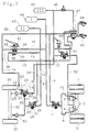
- Fig. 1 is a three-circuit brake system for shown a two-axle vehicle, the third circuit to supply a trailer brake system serves.
- a first axle serving as the rear axle (3) has two wheels (1) and (5).
- Any bike (1) or (5) is a spring-loaded brake cylinder trained brake cylinder (2) and (4) assigned.
- the two brake cylinders (2) and (4) are via pressure medium lines (6) and (10) to the outlet a first control valve device (7) is connected.
- the input of the first control valve device (7) is via a pressure medium line (8) with one as a pressure medium source for supply the brake cylinder (2) and (4) with pressure medium serving pressure medium reservoir (44) connected.
- the control input of the first control valve device (7) stands above pressure medium lines (9), (35) and (36) with one as a control output serving first pressure medium outlet (37) as Motor vehicle brake valve (41) designed multi-circuit brake value transmitter in connection.
- One of the first Pressure medium outlet (37) assigned to the first Pressure medium inlet (39) of the motor vehicle brake valve (41) is via a pressure medium line (42) and the pressure medium line (8) to the pressure medium reservoir (44) connected.
- the brake cylinders (2) and (4) of the rear axle (3) form together with the pressure medium lines (6) and (10), the first control valve device (7), the pressure medium lines (8), (9), (35) and (36), the motor vehicle brake valve (41) and the pressure medium line (42) and the pressure medium reservoir (44) a first serving as a rear axle brake circuit Brake circuit (I) of the vehicle brake system.
- a second axle serving as the front axle (32) of the vehicle has a first wheel (34) and second wheel (31).
- the first wheel (34) is a first brake cylinder (33) and the second wheel (31) a second brake cylinder (30) is assigned.
- a second brake cylinder (30) is via a pressure medium line (11) and one connected to it Pressure medium line (29) with the pressure medium outlet (28) a second control valve device (27) connected.
- a pressure medium inlet (26) of the second Control valve device (27) is via a pressure medium line (12) with a pressure medium reservoir (43) connected as the pressure medium source to supply the brake cylinders (33) and (30) Front axle (32) of the vehicle with pressure medium serves.
- a control input (25) of the second control valve device (27) stands over a pressure medium line (24) and one associated with it Pressure medium line (15) with a control output serving second pressure medium outlet (38) of the Motor vehicle brake valve (41) in connection.
- a assigned to the second pressure medium outlet (38) second pressure medium inlet (40) of the motor vehicle brake valve (41) is via a pressure medium line (14) and the pressure medium line (12) also with the pressure medium reservoir (43) connected.
- the first brake cylinder (33) of the front axle (32) is via a pressure medium line (23) and a additional control valve device (22) and Pressure medium line (11) with the pressure medium outlet (28) of the second control valve device (27).
- the additional control valve device (22) has a pressure medium inlet (18), one Pressure medium outlet (21), a control input (17) and usually to a fluid sink leading pressure medium outlet (20).
- Via a pressure medium line (13) and a this connected pressure medium line (46) is the pressure medium inlet (18) of the additional control valve device (22) with a pressure medium reservoir (45) in connection.
- To the pressure medium reservoir (45) are via the pressure medium line (46) and a valve device (47) two coupling heads (48) and (49) connected, to connect the braking system of the motor vehicle with the braking system of a trailer vehicle to serve.
- the pressure medium outlet (20) of the additional Control valve device (22) is over the Pressure medium line (11) and the pressure medium line (29) with the pressure medium outlet (28) of the second Control valve device (27) connected.
- the pressure medium outlet (21) the additional control valve device (22) is above the pressure medium line (23) with the first brake cylinder (33) Front axle (32) in connection.
- the control input (17) the additional control valve device (22) stands over a pressure medium line (16) and Pressure medium line (36) with the first pressure medium outlet (37) of the motor vehicle brake valve (41) in connection.
- the pressure medium inlet chamber is via the pressure medium inlet (18) the additional control valve device (22) with the pressure medium reservoir (45) connected and via the pressure medium outlet (20) and the second control valve device (27) is the pressure medium outlet chamber of the additional Control valve device (22) with the pressure medium reservoir (43) connectable.
- the additional control valve device (22) can be brought into the open position Check valve (19) arranged.
- the check valve (19) serves to secure the supply of the two brake cylinders (33) and (30) with Pressurizing medium reservoir (43) and of this pressure medium reservoir (43) independent pressure medium reservoir (45) against each other.
- the check valve (19) is between the pressure medium inlet (18) and the throttle (82) arranged.
- Another choke (83) is in the from the first pressure medium outlet (37) of the motor vehicle brake valve (41) to the control input (17) the additional control valve device (22) leading fluid line (16) near the Control input (17) arranged.
- This throttle can also, e.g. B. designed as an aperture, directly in Control input (17) can be arranged.
- the two brake cylinders (33) and (30) of the front axle (32), the pressure medium lines (23), (11) and (29), the second control valve device (27) and the additional control valve device (22) and the pressure medium lines (24), (15), (16) and (36), the motor vehicle brake valve (41), the Pressure fluid line (14) and the pressure fluid line (12) and the pressure medium reservoir (43) form a front brake circuit second brake circuit (II) for the pressure-operated Vehicle brake system.
- The are via a pressure medium line (52) Brake cylinder (2) and (4) of the rear axle (3) of the Vehicle with a pressure medium outlet of a hand brake valve (50) controllable valve (51) in connection, the pressure medium input via the pressure medium line (13) and the pressure medium line (46) with the pressure medium reservoir (45) is connected.
- the hand brake valve (50) is furthermore with a pressure medium inlet as Trailer control valve serving valve (47) connected.
- the valve devices (47) and (50) and the coupling heads (48, 49) and the associated Pressure fluid lines and the pressure fluid reservoir (45) form a trailer brake circuit serving third brake circuit (III) of the vehicle brake system.
- the first control valve device (7), the second Control valve device (27) and the additional Control valve device (22) are identical in construction and preferably designed as a commercially available relay valve, only the additional control valve device (22) a check valve (19) and optionally the throttles (83) and (82).
- FIG. 2 is the first brake cylinder (33) additional assigned to the front axle (32) of the vehicle Control valve device (22) in section shown.
- Control valve device has one as a control piston serving first relay piston (55) and one serving as a control piston second relay piston (77) on the one behind the other and coaxial to each other in a housing (53) and in Movable in the direction of the longitudinal axis of the housing (53) are.
- the second relay piston (77) has one smaller pressurizable media Effective area as the first relay piston (55).
- the first relay piston (55) limits with his the side facing away from the second relay piston (77) a pressure medium outlet chamber (59) and with it the side facing the second relay piston (77) a space (56) through an opening (78) in the Wall of the housing (53) connected to the atmosphere is.
- the second relay piston (77) limits with his the side facing the first relay piston (55) also the room (56) and with its first Relay piston (55) facing away from a control chamber (75).
- the first relay piston (55) applies its circumference a sealing ring (58), the sealing abuts the wall of the housing (53).
- the same carries the second relay piston (77) on its circumference a sealing ring (76), which is also sealing abuts the wall of the housing (53).
- the Sealing rings (58) and (76) and the opening (78) prevent an exchange of pressure medium between the control chamber (75) and the pressure medium outlet chamber (59) takes place.
- the second relay piston (77) has one centrally arranged, on the one hand towards the Control chamber (75) and on the other hand towards to extend the first relay piston (55) Extension (81) on.
- a blind hole is arranged centrally, in which is a peg-like projection of the housing (53) stretched in.
- the second relay piston (77) is on this pin-like projection of the Housing (53) slidably mounted.
- the first relay piston (55) also has one centrally arranged, towards the Pressure medium outlet chamber (59) to be extended Extension (54) on which a centrally arranged has stepped bore (80). In the hole (80) extends that of the first relay piston (55) facing, also graded area of the Extension (81) of the second relay piston (77) inside.
- the first relay piston (55) is on the stepped area of the extension (81) of the second Relay piston (77) slidably guided.
- a sealing ring (79) is arranged, which prevents the gap between the outer surface of the extension (81) and the wall defining the bore (80) of the extension (54) pressure medium from the pressure medium outlet chamber (59) enters the room (56) and escapes into the atmosphere through the opening (78).
- the first relay piston (55) and the second relay piston (77) becomes a combined one Inlet and outlet valve (61, 62, 60), via which the pressure medium outlet chamber (59) in Dependence on the position of the first relay piston (55) and the second relay piston (77) with a pressure medium inlet chamber (73) or with a pressure medium outlet (71, 20) can be connected, operated.
- the pressure medium outlet (71, 20) has the arrangement of the relay valve shown in Fig. 1 (22) function in a brake system both a pressure medium outlet as well as one Pressure medium inlet.
- the combined inlet and outlet valve (60, 61, 62) consists of a fixedly arranged in the housing (53) annular inlet valve seat (61) and a movable relative to this annular valve member (62), which by the Force of a spring (72) on the intake valve seat (61) and an exhaust valve seat (60), that of the free end of the centrically on the first Relay piston (55) arranged extension (54) is formed becomes.
- the extension (54) is coaxial with Inlet valve seat (61) and to the valve member (62) on arranged and extends the first relay piston (55) forming with the exhaust valve seat (60) free end area in the direction of the intake valve seat (61) and the valve member (62).
- valve member (62) On the side facing away from the exhaust valve seat (60) the valve member (62) is coaxial with the valve member (62) in the housing towards the valve member (62) tubular body to be extended arranged, the one facing the valve member Side is fork-shaped.
- the fork-shaped Area of the tubular body has an outer leg (69) and an inner Leg (70), which is parallel to the longitudinal axis of the Housing (53) run.
- the valve member (62) is as a U-shaped body formed so to the fork-shaped area of the tubular body is arranged that the inner leg of the valve member (62) on the outer Lateral surface of the inner leg (70) and the outer leg of the valve member (62) on the outer lateral surface of the outer leg (69) of the forked portion of the tubular body sealed sliding is guided.
- the feather (72) has one end supported on the bottom of the forked portion of the tubular body and lies on the floor with its other end of the U-shaped valve member (62). From the free interior of the tubular body the area (71) of the housing (53) Pressure fluid outlet (71, 20) formed with one outside the housing (53), as Pressure medium connection serving area (20) of the Pressure medium outlet (71, 20) is connected.
- the pressure medium input chamber (73) is from the outer lateral surface of the two legs (69) and (70) tubular body and of an annular wall (74) of the housing (53) delimits.
- a passage (68) is arranged in the wall (74), which is the fluid inlet chamber (73) connects to a pressure medium inlet (18).
- the pressure medium outlet (71, 20) is via the outlet valve (62, 60) of the combined inlet and Exhaust valve (60, 61, 62) with the pressure medium outlet chamber (59) connectable.
- the pressure medium inlet (18) is cup-shaped, being in the bottom (65) of the cup-shaped part a passage (64) is provided. Between the cup-shaped part of the pressure medium inlet (18) facing side of the wall (74) of the housing (53) and the bottom (65) of the cup-shaped part of the Pressure medium inlet (18) is a valve member (66) arranged, which of a itself on the wall (74) supporting spring (67) so on the floor (65) of the cup-shaped part of the pressure medium inlet (18) is held so that it closes the passage (64).
- the pressure medium inlet (18) is over a pressure medium line (13) with a pressure medium reservoir (45) connected.
- the floor (65), the passage (64) and the valve member (66) form one of the pressure medium of the pressure medium reservoir (45) towards the pressure medium inlet chamber (73) to open position bringable check valve (65, 64, 66).
- a throttle (82) arranged in the Pressure medium line (13) a throttle (82) arranged.
- the throttle (82) can also, for. B. as an aperture trained, arranged directly in the pressure medium inlet (18) will.
- the pressure medium outlet chamber (59) is via a Passage (57) in a pressure medium outlet (21) from the pressure medium outlet chamber (59) separating wall of the housing (53) is arranged, connected to the pressure medium outlet (21). Of the Pressure medium outlet (21) is via a pressure medium line (23) with the first brake cylinder (33) the front axle of the vehicle.
- a pressure medium inlet (26) of the second control valve device (27) is with a pressure medium line (12) Pressure medium reservoir (43) connected.
- a connectable to the second pressure medium outlet (38) second pressure medium inlet (40) of the motor vehicle brake valve (41) is via a pressure medium line (14) with the pressure medium reservoir (43) connected.
- the control chamber (75) of the relay valve (22) is with a control input (17) connected via a pressure medium line (16) and a pressure medium line connected to this (36) to a first pressure medium outlet (37) of the Motor vehicle brake valve (41) is connected.
- a throttle (83) is arranged in close to the control input (17) is in the pressure medium line (16) .
- the throttle (83) can, for. B. also designed as an aperture, arranged directly in the control input (17) will.
- One with the first pressure medium outlet (37) connectable first pressure medium inlet (39) of the Motor vehicle brake valve (41) has a this connected pressure medium line (42) and a Pressure medium line (8) with a further pressure medium reservoir (44) in connection.
- the control chamber (75) of the relay valve (22) is thus with that from the motor vehicle brake valve (41) whose first pressure medium outlet (37) is activated, as a control signal for the first brake circuit (I) (rear axle brake circuit) serving pressure.
- the pressure medium outlet chamber (59) is via the open outlet valve (60, 62) - when the valve is closed Inlet valve (61, 62) - the combined Inlet and outlet valves (60, 61, 62) and the pressure medium outlet (20, 71) of the relay valve (22) and the second control valve device (27) with the pressure of the second brake circuit (II) (Front axle brake circuit) assigned pressure medium reservoir (43) and via the open inlet valve (61, 62) - with the exhaust valve closed (60, 62) - the combined intake and exhaust valve (60, 61, 62) and the pressure medium inlet chamber (73) and the pressure medium inlet (18) of the relay valve (22) with the pressure of the Pressure medium reservoir (43) for the second Brake circuit (II) independent pressure medium
- the towing vehicle brake valve When the towing vehicle brake valve is not actuated (41) is the one designed as a relay valve additional control valve device (22) in the switch position shown.
- the inlet valve (61, 62) is closed and the outlet valve (62, 60) is open.
- the control chamber (75) is depressurized.
- the pressure medium outlet chamber (59) is by means of the intake valve (61, 62) against the pressure medium input chamber (73) shut off and via the outlet valve (62, 60), the pressure medium outlet (71, 20), the pressure medium line (11) and the open exhaust valve of the second control valve device (27) with the Pressure medium sink (atmosphere) connected.
- the one with the pressure medium outlet (21) of the additional control valve device (22) connected first brake cylinders (33) and that via the pressure medium lines (11) and (29) with the pressure medium outlet (28) second control valve device (27) connected second brake cylinder (30) of the front axle (32) are thus also via the exhaust valve second control valve device (27) with the Pressure medium sink (atmosphere) connected.
- the second control valve device (27) there is pressure medium from the pressure medium reservoir (43) of the second brake circuit (II).
- the pressure medium inlet (26) and the Pressure medium outlet (28) of the second control valve device (27) are by means of the In the closed position of the inlet valve second control valve device (27) against each other cordoned off.
- the first control valve device (7) pressure medium from the pressure medium reservoir (44) of the first Brake circuit (rear axle brake circuit).
- the Pressure medium outlet chamber and the pressure medium inlet chamber are the by means of an inlet valve first control valve device (7) against each other shut off and the pressure medium outlet chamber is via an outlet valve of the first control valve device (7) with the pressure medium sink (atmosphere) connected. So there are also those with the pressure medium outlet the first control valve device (7) connected brake cylinder (2) and (4) of the rear axle (3) with the pressure medium sink (atmosphere) in Connection.
- the control chamber of the first control valve device (7) is depressurized. At the first pressure fluid inlet (39) of the motor vehicle brake valve S.
- the motor vehicle brake valve (41) for the purpose of introduction of a braking operation is actuated the valve devices of the motor vehicle brake valve (41) switched in such a way that the Pressure medium outlets (37) and (38) of the motor vehicle brake valve (41) with those assigned to them Pressure medium inputs (39) and (40) of the motor vehicle brake valve (41) can be connected.
- the first control valve device (7) and the second control valve device (27) switch in such a way that the Pressure medium outlet chamber of the first control valve device (7) shut off against the pressure fluid sink and with the pressure medium input chamber assigned to it is connected and so is the Pressure medium outlet chamber of the second control valve device (27) shut off against the pressure fluid sink and with the pressure medium input chamber assigned to it is connected.
- the brake cylinders (2) and (4) of the rear axle (3) then with the from the first control valve device (7) modulated, from the control pressure pressure dependent on the first brake circuit (I), until the first control valve device (7) has reached a final position (inlet and Exhaust valve closed).
- the pressure medium inlet chamber (73) and the pressure medium outlet chamber (59) the additional control valve device (22) are intact second Brake circuit (II) by means of the closed inlet valve (61, 62) of the additional control valve device (22) always cordoned off from each other.
- the additional control valve device (22) Since the control pressure in the control chamber (75) acted area of the second relay piston (77) the additional control valve device (22) is smaller than that opposite from the pressure in the pressure medium outlet chamber (59) acted on Effective area of the first relay piston (55), the from the control pressure to the second relay piston (77) exerted force that counteracts this force force exerted on the first relay piston (55) the pressure in the pressure medium outlet chamber (59) not overcome, so that on the first relay piston (55) adjacent second relay pistons (77) first relay piston (55) not towards combined inlet and outlet valve (60, 61, 62) can move.
- the additional control valve device (22) Because the pressure build-up in the control chamber (75) the additional control valve device (22), due to the throttle (83), takes place more slowly than the pressure build-up in the Pressure medium outlet chamber (59) of the additional Control valve device (22), it can also at the beginning the pressure control does not become an unwanted one Operation of the combined inlet and Exhaust valve (60, 61, 62) by means of the relay piston (55) and (77) are coming.
- the Throttle (82) in front of the pressure medium inlet (18) achieved that the pressure build-up in the pressure medium input chamber (73) the additional control valve device (22) primarily with that over the others Pressure medium inlet (20) controlled pressure of the second brake circuit (II).
- the first valve is depressurized Control valve device (7) and the outlet valve the second control valve device (27) in their open position.
- the pressure medium outlet chamber (59) of the additional control valve device (22) and thus also the first brake cylinder (33) Front axle (32) are opened through the exhaust valve (60, 62) and the pressure medium outlet (71, 20) the additional control valve device (22) and the open exhaust valve with the additional one Control valve device (22) connected second control valve device (27) to the atmosphere vented out.
- the second Brake cylinder (30) of the front axle (32) over the vented second control valve device (27).
- the Brake cylinder (2) and (4) of the rear axle (3) of the Vehicle are via the first control valve device (7) vented.
- the valve member (62) With the further downward movement the relay piston (55) and (77) the valve member (62) is lifted off the inlet valve seat (61). The inlet valve (61, 62) is then open. Flows out of the pressure medium inlet chamber (73) Pressure medium from the pressure medium reservoir (45) of the third brake circuit (III) through the open Inlet valve (61, 62) in the pressure medium outlet chamber (59) and from there through the passage (57) in the pressure medium outlet (21). From the additional control valve device (22) then becomes one of the pressure at the first pressure medium outlet (37) of the motor vehicle brake valve (41) Pressure from the third brake circuit (III) controlled. This comes from the pressure medium outlet (21) Pressure medium through the pressure medium line (23) to first brake cylinder (33) of the wheel (34) of the front axle (32) of the vehicle.
- the one in the Pressure medium outlet chamber (59) building pressure causes the first relay piston to move (55) and thus also the second relay piston (77) against the force of the control pressure in the control chamber (75) towards the control chamber (75) to.
- the first relay piston counteracts this force Exerted force reaches the inlet valve (61, 62) in the closed position and one Final position has been reached.
- the motor vehicle brake valve is used to stop the braking process (41) to its starting position brought, so the connection between the Control chamber (75) of the additional control valve device (22) and the pressure medium reservoir (44) of the first brake circuit (I) by means of of the motor vehicle brake valve (41) interrupted.
- the Control chamber (75) is via the motor vehicle brake valve (41) vented to the atmosphere.
- the relay piston (55) and (77) the pressure in the pressure medium outlet chamber (59) continue towards the control chamber (75) moved.
- the outlet valve (60, 62) is then open. About the open outlet valve (60, 62) the pressure from the pressure medium outlet chamber (59) via the pressure medium outlet (71, 20) and the open Exhaust valve of the second control valve device (27) or a possible breaking point in the Pressure medium line (11) reduced to the atmosphere.
- an additional Control valve device in one of the two pressure medium line branches of a pressure medium line which the pressure medium outlet one the Brake cylinders assigned to the front axle of a vehicle Control valve device with the two Connecting brake cylinders to the front axle ensures that if the front axle brake circuit fails (second brake circuit II) at least one wheel the front axle of the vehicle can still be braked can.
- the additional control valve device (22) can have two relay pistons (55) and (77) whose different effective areas acted upon by the pressure medium Have size, as in the embodiment wrote.
- the Step piston must then in the housing of the additional Valve device be arranged that its the smaller diameter side Tax chamber limited. This ensures that the relay piston or the combined inlet and outlet valve of the additional control valve device cannot or cannot operate can, if at the same time control pressure medium in the Control chamber and brought up via the pressure medium outlet Pressure medium in the pressure medium outlet chamber is available.
- the vehicle brake system according to the invention can pneumatic, hydraulic or also electric be controllable.
- the multi-circuit brake value transmitter at least one electrical device, such as. B. a potentiometer, and at least one electric one Have control output, the electrical Control output of the multi-circuit brake value transmitter then with an electrical control input one electrically associated with at least one brake cylinder controllable control valve device to connect is.
- an electrical control signal for controlling the Brake pressure can e.g. B. one from the position of Actuator (pedal) of the multi-circuit brake value transmitter dependent electrical signal.
- the control valve device can then be an electrical one Control means z. B. an associated with the tax chamber Have proportional solenoid valve. It is of course also possible, the control valve device or the control valve devices as one of electrical control signals of the Multi-circuit brake value transmitter controllable pressure modulator or to design controllable pressure modulators.
- the multi-circuit brake value transmitter as a motor vehicle brake valve trained for a motor vehicle, being from this motor vehicle brake valve a first brake circuit (rear axle brake circuit) assigned pneumatic control signal and a a second brake circuit (front axle brake circuit) assigned pneumatic control signal generated will.
- the three control valve devices are according to the embodiment for the claimed Invention as a pneumatically controllable control valve device educated.
- the application of the invention should of course be understood not on the brakes on the front axle Vehicle.
- the invention can are also used on the brakes on the rear axle or on the brakes of additional axles of the Vehicle.
Landscapes
- Engineering & Computer Science (AREA)
- Transportation (AREA)
- Mechanical Engineering (AREA)
- Physics & Mathematics (AREA)
- Fluid Mechanics (AREA)
- Regulating Braking Force (AREA)
Applications Claiming Priority (2)
| Application Number | Priority Date | Filing Date | Title |
|---|---|---|---|
| DE19504393 | 1995-02-10 | ||
| DE19504393A DE19504393C1 (de) | 1995-02-10 | 1995-02-10 | Druckmittelbetätigte Fahrzeugbremsanlage |
Publications (2)
| Publication Number | Publication Date |
|---|---|
| EP0726190A1 EP0726190A1 (de) | 1996-08-14 |
| EP0726190B1 true EP0726190B1 (de) | 1998-07-29 |
Family
ID=7753617
Family Applications (1)
| Application Number | Title | Priority Date | Filing Date |
|---|---|---|---|
| EP95120563A Expired - Lifetime EP0726190B1 (de) | 1995-02-10 | 1995-12-27 | Druckmittelbetätigte Fahrzeugbremsanlage |
Country Status (5)
| Country | Link |
|---|---|
| US (1) | US5700063A (cs) |
| EP (1) | EP0726190B1 (cs) |
| BR (1) | BR9600366A (cs) |
| CZ (1) | CZ37996A3 (cs) |
| DE (2) | DE19504393C1 (cs) |
Cited By (2)
| Publication number | Priority date | Publication date | Assignee | Title |
|---|---|---|---|---|
| EP1099611A2 (de) | 1999-11-12 | 2001-05-16 | KNORR-BREMSE SYSTEME FÜR NUTZFAHRZEUGE GmbH | Druckmittelbetätigte Fahrzeugbremsanlage |
| DE102008035335A1 (de) | 2008-07-29 | 2010-02-04 | Man Nutzfahrzeuge Aktiengesellschaft | Druckmittelbetätigte Bremsvorrichtung für Kraftfahrzeuge |
Families Citing this family (24)
| Publication number | Priority date | Publication date | Assignee | Title |
|---|---|---|---|---|
| DE19514603C2 (de) * | 1995-04-20 | 1997-04-03 | Daimler Benz Ag | Druckluft-Bremsanlage für ein Nutzfahrzeug |
| DE19545640B4 (de) * | 1995-12-07 | 2006-01-19 | Wabco Gmbh & Co.Ohg | Steuerventileinrichtung |
| JP3827250B2 (ja) * | 1996-07-02 | 2006-09-27 | トヨタ自動車株式会社 | ブレーキ液圧制御装置 |
| DE19746342A1 (de) * | 1997-10-21 | 1999-04-22 | Wabco Gmbh | Druckmittelbetätigte Fahrzeugbremsanlage |
| DE19923455C2 (de) * | 1999-05-21 | 2001-03-15 | Knorr Bremse Systeme | Druckmittelbetätigte Fahrzeugbremsanlage |
| DE19932470B4 (de) | 1999-07-12 | 2008-08-28 | Knorr-Bremse Systeme für Nutzfahrzeuge GmbH | Druckmittelbetätigte Fahrzeugbremsanlage |
| DE19933481A1 (de) * | 1999-07-16 | 2001-01-25 | Knorr Bremse Systeme | Druckmittelbetätigte Fahrzeugbremsanlage |
| DE19933483C1 (de) * | 1999-07-16 | 2000-10-26 | Knorr Bremse Systeme | Druckmittelbetätigte Fahrzeugbremsanlage |
| DE19935979C2 (de) * | 1999-07-30 | 2001-07-19 | Knorr Bremse Systeme | Druckmittelbetätigte Fahrzeugbremsanlage |
| DE10004086C2 (de) * | 2000-01-31 | 2001-12-06 | Knorr Bremse Systeme | Bremsanlage für Fahrzeuge, insbesondere Nutzfahrzeuge |
| DE10042215C5 (de) * | 2000-08-28 | 2005-09-01 | Knorr-Bremse Systeme für Nutzfahrzeuge GmbH | Druckmittelbetätigte Fahrzeugbremsanlage mit redundanter Ansteuerung wenigstens eines Bremszylinders |
| DE10129602A1 (de) * | 2001-06-20 | 2003-01-09 | Knorr Bremse Systeme | Kombinierte elektro-pneumatisch und mechanisch betätigbare Ventileinrichtung und Steuervorrichtung für ein Bremssystem |
| DE10155952B4 (de) * | 2001-11-14 | 2006-04-20 | Knorr-Bremse Systeme für Nutzfahrzeuge GmbH | Bremsanlage für ein Kraftfahrzeug |
| DE10230314B4 (de) * | 2002-07-05 | 2013-10-24 | Iveco Magirus Ag | Bremsvorrichtung für Fahrzeuge, insbesondere Lastkraftwagen |
| DE10236921B4 (de) * | 2002-08-12 | 2005-09-29 | Knorr-Bremse Systeme für Nutzfahrzeuge GmbH | Elektronisches Bremssystem mit einer Abreissfunktion |
| ITTO20030248A1 (it) * | 2003-04-01 | 2004-10-02 | Knorr Bremse Systeme | Sistema pneumatico di frenatura per un autoveicolo. |
| US7008025B2 (en) | 2004-01-30 | 2006-03-07 | Arvinmeritor Technology, Llc | Electronic vehicle brake system with secondary braking provision |
| DE102005042673A1 (de) * | 2005-09-08 | 2007-03-15 | Man Nutzfahrzeuge Ag | Druckluftbremsanlage für ein Kraftfahrzeug |
| DE102007004759B4 (de) * | 2007-01-31 | 2010-09-30 | Knorr-Bremse Systeme für Nutzfahrzeuge GmbH | Bremsanlage und Verfahren zum Steuern einer Bremsanlage für ein Nutzfahrzeug |
| DE102007038288A1 (de) * | 2007-08-14 | 2009-02-19 | Man Nutzfahrzeuge Ag | Hilfsbremsvorrichtung für Nutzfahrzeuge |
| US8820857B2 (en) * | 2011-10-13 | 2014-09-02 | Bendix Commercial Vehicle Systems Llc | Apparatus and method for preventing parking brake-caused vehicle disabling |
| DE102016114831A1 (de) | 2016-08-10 | 2018-02-15 | Knorr-Bremse Systeme für Nutzfahrzeuge GmbH | Mehrfachrelaisventil sowie pneumatisches Bremssystem mit wenigstens einem Mehrfachrelaisventil |
| WO2019036276A1 (en) * | 2017-08-14 | 2019-02-21 | Hendrickson Usa, L.L.C. | PNEUMATIC BRAKE SYSTEM |
| DE102023112642A1 (de) * | 2023-05-12 | 2024-11-14 | Daimler Truck AG | Druckluft-Bremsvorrichtung und Kraftfahrzeug mit einer solchen Druckluft-Bremsvorrichtung |
Family Cites Families (14)
| Publication number | Priority date | Publication date | Assignee | Title |
|---|---|---|---|---|
| US4003605A (en) * | 1975-11-28 | 1977-01-18 | The Bendix Corporation | Fluid pressure braking system with limiting valve for anti-compounding and fail-safe standby valve |
| EP0000249B1 (en) * | 1977-06-25 | 1982-07-28 | Bendix Limited | Fluid pressure operable tractor and trailer vehicle braking systems |
| DE2738948C2 (de) * | 1977-08-30 | 1986-09-18 | Knorr-Bremse AG, 8000 München | Drucksteuerventil zur Steuerung des Vorderachsbremsdruckes in pneumatischen Zweikreis-Fahrzeugbremsanlagen |
| BR7904833A (pt) * | 1978-08-01 | 1981-02-03 | Girling Midland Ross Air Act | Valvula piloto aperfeicoada |
| DE3144961A1 (de) * | 1981-11-12 | 1983-05-19 | Robert Bosch Gmbh, 7000 Stuttgart | Druckmittel-bremsanlage |
| DE3144963A1 (de) * | 1981-11-12 | 1983-05-19 | Robert Bosch Gmbh, 7000 Stuttgart | Druckmittel-bremsanlage |
| DE3204185A1 (de) * | 1982-02-06 | 1983-08-11 | Robert Bosch Gmbh, 7000 Stuttgart | Druckmittel-bremsanlage |
| DE3230970A1 (de) * | 1982-08-20 | 1984-02-23 | Bosch Gmbh Robert | Mehrkreis-bremsanlage |
| DE3545021C2 (de) * | 1985-12-19 | 1996-09-12 | Bosch Gmbh Robert | Elektro-pneumatische Bremsanlage |
| DE3544965C2 (de) * | 1985-12-19 | 1994-08-11 | Bosch Gmbh Robert | Druckmittelbetätigte Bremsanlage |
| US4673222A (en) * | 1986-01-31 | 1987-06-16 | Allied Corporation | Tractor air pressure braking system |
| US4949492A (en) * | 1989-09-29 | 1990-08-21 | Prezine, Inc. | Quick release magazine catch |
| US5255961A (en) * | 1989-11-01 | 1993-10-26 | Graham John M | Multi-chamber brake actuator |
| DE4140271A1 (de) * | 1991-12-06 | 1993-06-09 | Robert Bosch Gmbh, 7000 Stuttgart, De | Druckluft-bremsanlage, insbesondere fuer nutzfahrzeuge |
-
1995
- 1995-02-10 DE DE19504393A patent/DE19504393C1/de not_active Expired - Fee Related
- 1995-12-27 EP EP95120563A patent/EP0726190B1/de not_active Expired - Lifetime
- 1995-12-27 DE DE59502982T patent/DE59502982D1/de not_active Expired - Lifetime
-
1996
- 1996-02-05 US US08/596,833 patent/US5700063A/en not_active Expired - Lifetime
- 1996-02-08 CZ CZ96379A patent/CZ37996A3/cs unknown
- 1996-02-09 BR BR9600366A patent/BR9600366A/pt not_active Application Discontinuation
Cited By (5)
| Publication number | Priority date | Publication date | Assignee | Title |
|---|---|---|---|---|
| EP1099611A2 (de) | 1999-11-12 | 2001-05-16 | KNORR-BREMSE SYSTEME FÜR NUTZFAHRZEUGE GmbH | Druckmittelbetätigte Fahrzeugbremsanlage |
| EP1099611A3 (de) * | 1999-11-12 | 2003-07-30 | KNORR-BREMSE SYSTEME FÜR NUTZFAHRZEUGE GmbH | Druckmittelbetätigte Fahrzeugbremsanlage |
| DE102008035335A1 (de) | 2008-07-29 | 2010-02-04 | Man Nutzfahrzeuge Aktiengesellschaft | Druckmittelbetätigte Bremsvorrichtung für Kraftfahrzeuge |
| EP2154041A2 (de) | 2008-07-29 | 2010-02-17 | MAN Nutzfahrzeuge AG | Druckmittelbetätigte Bremsvorrichtung für Kraftfahrzeuge |
| RU2412837C1 (ru) * | 2008-07-29 | 2011-02-27 | Ман Нутцфарцойге Акциенгезелльшафт | Тормозной механизм для автомобилей, приводимый в действие сжатой средой |
Also Published As
| Publication number | Publication date |
|---|---|
| BR9600366A (pt) | 1998-01-27 |
| CZ37996A3 (en) | 1996-08-14 |
| DE19504393C1 (de) | 1996-03-07 |
| EP0726190A1 (de) | 1996-08-14 |
| DE59502982D1 (de) | 1998-09-03 |
| US5700063A (en) | 1997-12-23 |
Similar Documents
| Publication | Publication Date | Title |
|---|---|---|
| EP0726190B1 (de) | Druckmittelbetätigte Fahrzeugbremsanlage | |
| EP2426021B1 (de) | Parkventil für einen Nutzfahrzeug-Anhänger | |
| EP2058187B1 (de) | Feststellbremsventil für eine Steueranlage für Kraftfahrzeug- Anhänger mit Betriebsbremse, Feststellbremse und Luftfederung | |
| DE3920766A1 (de) | Unterdruckbremskraftverstaerker fuer eine schlupfgeregelte bremsanlage | |
| DE3529744A1 (de) | Schlupfgeregelte bremsanlage fuer kraftfahrzeuge | |
| EP3190015A1 (de) | Bremseinrichtung eines zugfahrzeugs und gruppe von bremseinrichtungen | |
| EP0726189B1 (de) | Druckmittelbetätigte Fahrzeugbremsanlage | |
| DE202018001859U1 (de) | Bremssystem eines Zugfahrzeugs | |
| EP1060966A2 (de) | Anhängerbremsventil für blockiergeschützte Druckluftbremsanlagen von Anhängern | |
| EP0911237B1 (de) | Druckmittelbetätigte Fahrzeugbremsanlage | |
| DE3818617C2 (cs) | ||
| DE69014487T2 (de) | Druckluftbremsanlage. | |
| DE19639464A1 (de) | Zweikreisig hydraulisch ansteuerbares Anhängersteuerventil | |
| DE102017005757A1 (de) | Notlöseventil und Feststellbremsmodul einer Druckluftbremsanlage | |
| DE2856726A1 (de) | Servogestuetztes hydraulik-bremssystem fuer motorfahrzeuge | |
| EP3429898B1 (de) | Park-löse-ventil für ein anhängefahrzeug | |
| DE10042215C1 (de) | Druckmittelbetätigte Fahrzeugbremsanlage mit redundanter Ansteuerung wenigstens eines Bremszylinders | |
| DE3542601A1 (de) | Schlupfgeregelte bremsanlage | |
| DE2354458B2 (de) | Lenkbremseinrichtung für hydraulisch bremsbare Kraftfahrzeuge mit Anhänger, insbesondere Schlepper mit Anhänger | |
| DE3229836C2 (de) | Über zwei Kreise ansteuerbares Anhänger-Steuerventil, insbes. für Druckluftbremsanlagen an Kraftfahrzeugen | |
| DE3041736C2 (de) | Steuerventilanordnung für den Hydraulikdruck bei einem Zweikreis-Bremssystem | |
| DE2154229C3 (de) | Hilfskraftunterstützte, hydraulische Bremsbetätigungsanlage, insbesondere für Kraftfahrzeuge | |
| DE4438154C2 (de) | Umschaltventil für mehrkreisige Bremsanlagen von Kraftfahrzeugen | |
| DE3242982C2 (cs) | ||
| DE3234291C2 (cs) |
Legal Events
| Date | Code | Title | Description |
|---|---|---|---|
| PUAI | Public reference made under article 153(3) epc to a published international application that has entered the european phase |
Free format text: ORIGINAL CODE: 0009012 |
|
| 17P | Request for examination filed |
Effective date: 19960617 |
|
| AK | Designated contracting states |
Kind code of ref document: A1 Designated state(s): DE FR GB IT NL SE |
|
| RAP1 | Party data changed (applicant data changed or rights of an application transferred) |
Owner name: DAIMLER-BENZ AKTIENGESELLSCHAFT Owner name: WABCO GMBH |
|
| GRAG | Despatch of communication of intention to grant |
Free format text: ORIGINAL CODE: EPIDOS AGRA |
|
| 17Q | First examination report despatched |
Effective date: 19971117 |
|
| GRAG | Despatch of communication of intention to grant |
Free format text: ORIGINAL CODE: EPIDOS AGRA |
|
| GRAG | Despatch of communication of intention to grant |
Free format text: ORIGINAL CODE: EPIDOS AGRA |
|
| GRAH | Despatch of communication of intention to grant a patent |
Free format text: ORIGINAL CODE: EPIDOS IGRA |
|
| GRAH | Despatch of communication of intention to grant a patent |
Free format text: ORIGINAL CODE: EPIDOS IGRA |
|
| GRAA | (expected) grant |
Free format text: ORIGINAL CODE: 0009210 |
|
| AK | Designated contracting states |
Kind code of ref document: B1 Designated state(s): DE FR GB IT NL SE |
|
| ITF | It: translation for a ep patent filed | ||
| REF | Corresponds to: |
Ref document number: 59502982 Country of ref document: DE Date of ref document: 19980903 |
|
| GBT | Gb: translation of ep patent filed (gb section 77(6)(a)/1977) |
Effective date: 19981029 |
|
| ET | Fr: translation filed | ||
| RAP2 | Party data changed (patent owner data changed or rights of a patent transferred) |
Owner name: DAIMLERCHRYSLER AG Owner name: WABCO GMBH |
|
| NLT2 | Nl: modifications (of names), taken from the european patent patent bulletin |
Owner name: WABCO GMBH EN DAIMLERCHRYSLER AG |
|
| PLBE | No opposition filed within time limit |
Free format text: ORIGINAL CODE: 0009261 |
|
| STAA | Information on the status of an ep patent application or granted ep patent |
Free format text: STATUS: NO OPPOSITION FILED WITHIN TIME LIMIT |
|
| 26N | No opposition filed | ||
| PGFP | Annual fee paid to national office [announced via postgrant information from national office to epo] |
Ref country code: GB Payment date: 20001227 Year of fee payment: 6 |
|
| PGFP | Annual fee paid to national office [announced via postgrant information from national office to epo] |
Ref country code: NL Payment date: 20001231 Year of fee payment: 6 |
|
| PG25 | Lapsed in a contracting state [announced via postgrant information from national office to epo] |
Ref country code: GB Free format text: LAPSE BECAUSE OF NON-PAYMENT OF DUE FEES Effective date: 20011227 |
|
| REG | Reference to a national code |
Ref country code: GB Ref legal event code: IF02 |
|
| PG25 | Lapsed in a contracting state [announced via postgrant information from national office to epo] |
Ref country code: NL Free format text: LAPSE BECAUSE OF NON-PAYMENT OF DUE FEES Effective date: 20020701 |
|
| GBPC | Gb: european patent ceased through non-payment of renewal fee |
Effective date: 20011227 |
|
| NLV4 | Nl: lapsed or anulled due to non-payment of the annual fee |
Effective date: 20020701 |
|
| PGFP | Annual fee paid to national office [announced via postgrant information from national office to epo] |
Ref country code: IT Payment date: 20081223 Year of fee payment: 14 |
|
| PG25 | Lapsed in a contracting state [announced via postgrant information from national office to epo] |
Ref country code: IT Free format text: LAPSE BECAUSE OF NON-PAYMENT OF DUE FEES Effective date: 20091227 |
|
| PGFP | Annual fee paid to national office [announced via postgrant information from national office to epo] |
Ref country code: SE Payment date: 20141208 Year of fee payment: 20 Ref country code: DE Payment date: 20141231 Year of fee payment: 20 |
|
| PGFP | Annual fee paid to national office [announced via postgrant information from national office to epo] |
Ref country code: FR Payment date: 20141229 Year of fee payment: 20 |
|
| REG | Reference to a national code |
Ref country code: DE Ref legal event code: R071 Ref document number: 59502982 Country of ref document: DE |
|
| REG | Reference to a national code |
Ref country code: SE Ref legal event code: EUG |