EP0725194A1 - Drainage device for balconies - Google Patents
Drainage device for balconies Download PDFInfo
- Publication number
- EP0725194A1 EP0725194A1 EP96101255A EP96101255A EP0725194A1 EP 0725194 A1 EP0725194 A1 EP 0725194A1 EP 96101255 A EP96101255 A EP 96101255A EP 96101255 A EP96101255 A EP 96101255A EP 0725194 A1 EP0725194 A1 EP 0725194A1
- Authority
- EP
- European Patent Office
- Prior art keywords
- profile
- section
- dirty water
- drainage system
- channel
- Prior art date
- Legal status (The legal status is an assumption and is not a legal conclusion. Google has not performed a legal analysis and makes no representation as to the accuracy of the status listed.)
- Granted
Links
Images


Classifications
-
- E—FIXED CONSTRUCTIONS
- E04—BUILDING
- E04D—ROOF COVERINGS; SKY-LIGHTS; GUTTERS; ROOF-WORKING TOOLS
- E04D13/00—Special arrangements or devices in connection with roof coverings; Protection against birds; Roof drainage; Sky-lights
- E04D13/04—Roof drainage; Drainage fittings in flat roofs, balconies or the like
- E04D13/064—Gutters
- E04D13/072—Hanging means
- E04D13/0727—Hanging means situated mainly at the rear side of the gutter
-
- E—FIXED CONSTRUCTIONS
- E04—BUILDING
- E04D—ROOF COVERINGS; SKY-LIGHTS; GUTTERS; ROOF-WORKING TOOLS
- E04D13/00—Special arrangements or devices in connection with roof coverings; Protection against birds; Roof drainage; Sky-lights
- E04D13/04—Roof drainage; Drainage fittings in flat roofs, balconies or the like
- E04D13/0404—Drainage on the roof surface
- E04D13/0459—Drainage borders, e.g. dripping edges, gravel stops or dispersers
-
- E—FIXED CONSTRUCTIONS
- E04—BUILDING
- E04D—ROOF COVERINGS; SKY-LIGHTS; GUTTERS; ROOF-WORKING TOOLS
- E04D13/00—Special arrangements or devices in connection with roof coverings; Protection against birds; Roof drainage; Sky-lights
- E04D13/04—Roof drainage; Drainage fittings in flat roofs, balconies or the like
- E04D13/064—Gutters
-
- E—FIXED CONSTRUCTIONS
- E04—BUILDING
- E04D—ROOF COVERINGS; SKY-LIGHTS; GUTTERS; ROOF-WORKING TOOLS
- E04D13/00—Special arrangements or devices in connection with roof coverings; Protection against birds; Roof drainage; Sky-lights
- E04D13/15—Trimming strips; Edge strips; Fascias; Expansion joints for roofs
- E04D13/155—Trimming strips; Edge strips; Fascias; Expansion joints for roofs retaining the roof sheathing
-
- E—FIXED CONSTRUCTIONS
- E04—BUILDING
- E04D—ROOF COVERINGS; SKY-LIGHTS; GUTTERS; ROOF-WORKING TOOLS
- E04D13/00—Special arrangements or devices in connection with roof coverings; Protection against birds; Roof drainage; Sky-lights
- E04D13/04—Roof drainage; Drainage fittings in flat roofs, balconies or the like
- E04D13/0404—Drainage on the roof surface
- E04D13/0459—Drainage borders, e.g. dripping edges, gravel stops or dispersers
- E04D2013/0463—Dispersers
-
- E—FIXED CONSTRUCTIONS
- E04—BUILDING
- E04D—ROOF COVERINGS; SKY-LIGHTS; GUTTERS; ROOF-WORKING TOOLS
- E04D13/00—Special arrangements or devices in connection with roof coverings; Protection against birds; Roof drainage; Sky-lights
- E04D13/04—Roof drainage; Drainage fittings in flat roofs, balconies or the like
- E04D13/0404—Drainage on the roof surface
- E04D13/0459—Drainage borders, e.g. dripping edges, gravel stops or dispersers
- E04D2013/0468—Drip edges
Definitions
- the invention relates to a drainage system for balconies, which consist of a support plate and screed applied thereon.
- the drainage system comprises at least one elongated end profile, which has an essentially flat anchoring leg that can be placed on the supporting plate of the balcony before the screed is applied, on the outside of the balcony of which there is a profile section that protects the supporting plate and the screed from external weather influences.
- This profile section is composed of a profile leg which has approximately the height of the screed and essentially protrudes upward at right angles and a profile leg which points obliquely downwards and at least partially covers the support plate.
- Such an end profile is known from German utility model 90 04 119. This end profile is used to keep driving rain or liquid flowing off the front edge of the balcony away from the front wall of the balcony, so that no moisture can penetrate into the screed or the support plate from there.
- the invention has for its object to provide a drainage system for balconies, which allows a drainage of dirty water such that an underlying balcony - or even a ground floor terrace - is not affected by dirty water discharged from the balcony above, without doing so on conventional gutters to have to fall back.
- This object is achieved in that in a drainage system of the type mentioned in the a wastewater drainage channel is provided at an angle downwards.
- the cross section of the dirty water drainage channel can be essentially U-shaped or also arch-like.
- the dirty water drainage channel projects beyond at least one of the two ends of the elongated end profile. This ensures that in the dirty water channel of a balcony, waste water running to this end is drained away without further measures in a direction away from the balconies or a terrace below this balcony.
- the dirty water drainage channel can have an opening facing away from the balcony, on which a dirty water spout is provided.
- wastewater spout is understood to mean a short water baffle or pipe.
- the opening can be provided at any point in the longitudinal direction of the profile, so that it is possible to discharge the dirty water from the dirty water drainage channel at a desired, advantageous point.
- the waste water drainage channel is an integral part of the end profile. This allows a cost-effective production of the end profile and waste water drainage channel in a single operation, e.g. in the extrusion process.
- the dirty water drainage channel is a separately manufactured component that can be attached to the end profile.
- Such a design of the end profile allows attachment of the Dirty water drainage channel even after completion of the balcony.
- a particularly advantageous way of attaching the waste water drainage channel to the end profile is possible if the obliquely downward profile leg of the end profile has an elongated groove-like depression with a narrowed mouth, into which the dirty water drainage channel can then be inserted or hooked.
- Such a configuration of the end profile and the waste water drainage channel makes it easy to install the waste water drainage channel without additional tools or fastening means such as e.g. Screws or rivets possible.
- End profiles are known in which a profile strip which is bent downward into a position approximately parallel to the side wall of the balcony is connected at the edge of the profile leg facing away from the anchoring leg.
- an elongated groove-like depression with a narrowed mouth which extends in the longitudinal direction of the profile and into which the dirty water drainage channel can be inserted or hooked in, is then provided on this profile strip.
- the end face of the profile strip facing away from the sloping downward profile leg can beveled towards the balcony, so that a drip edge for the dirty water forms on the side of the end face facing away from the balcony.
- the said narrowed mouths can be formed by two rib-like strip sections formed on the end profile at a parallel distance from the associated flat side.
- This has the advantage that the recess simple and inexpensive - in the case of a metallic end profile, for example in the extrusion process - can be produced, so that such a depression does not have to be subsequently milled into the profile, for example.
- the advantageous type of manufacture will be discussed in the description of the figures.
- a stiffening effect is achieved with these rib-like strip sections, which stiffens the end profile both during installation and during transport and makes it less susceptible to twisting. This means that such end profiles are bent less frequently during transport and are therefore rendered unusable.
- the stiffening and reinforcing effect not only has a positive effect during transport, it is also much easier to install on site with a stiffer profile than with a flexible one.
- the dirty water drainage channel can advantageously be designed such that a fastening section running in the longitudinal direction of the channel is provided, which can be inserted or hooked into the groove-like recess of the end profile and which has a cross section which is at least partially complementary to the cross section of the groove-like recess.
- the fastening section can have a strip section covering the side of the narrowed mouth facing away from the groove-like recess, a strip section penetrating the mouth and a strip section attached to the recess-side end of the strip section penetrating the mouth, approximately parallel to the strip section which forms an inner surface of the recess and forms the end profile.
- the height of the strip section folded over parallel to the inner surface of the depression opposite the mouth is maximally the same to measure the width of the mouth of the groove-like recess, so that the dirty water drainage channel can be hung anywhere in the end profile.
- the attachment can be facilitated in that the flank of the strip section pointing from the drainage channel to the flat section of the end profile which is parallel to the flat surface of the recess forming an inner surface of the recess is beveled at least over part of its height towards the strip section passing through the mouth.
- a dirty water spout can be arranged at at least one end of the channel. This spout drains the dirty water in any direction.
- a separately produced end cap can be slid onto one end of the sewage channel, which closes the channel at this end in a watertight manner at the side and downwards.
- the drainage system has at least one further elongated end profile (feed profile) for the lateral balcony edges, which has an essentially flat anchoring leg, on the balcony edge of which a waste water feed channel opening into or above the waste water drainage channel is arranged.
- feed profile elongated end profile
- corner connecting elements can be made of metal or plastic, whereby by using suitable plastics with a certain elasticity, length changes of the generally metallic waste water drainage channels or supply channels due to thermal expansion can advantageously be compensated for.
- the feed profile has a profile leg that at least partially covers the screed. This profile leg protects the support plate from external weather influences.
- the underside of the anchoring leg facing the screed can be provided, at least in sections, with surface-enlarging recesses.
- an advantageously developed drainage system in which an essentially vertically downward-pointing profile leg of the end profile points downward Profile strip is provided, which has an elongated recess with a narrowed mouth, on which an elongated substantially strip-shaped guide screen by means of a narrowed to the Mouth at least partially complementary fastening section can be fastened to the end profile.
- a waste water drainage channel can then be fastened to such a guide screen. If the contamination of an arial located under the balcony does not turn out to be critical, then instead of a dirty water drainage channel, only the elongated strip-shaped dirty water guide screen is attached. However, if the contamination proves to be critical, a waste water drainage channel can be attached to the guide panel at any time.
- this dirty water drain channel is clamped to the guide screen by means of at least one screw-nut connection, an opening for the screw being provided in the guide screen and in the dirty water drain channel, one of the openings being essentially circular Cross-section has, while the other is designed as an elongated hole in such a way that the waste water drainage channel can be attached to the guide screen in a manner that is variable in height and / or inclination.
- Fig. 1 shows a plan view of a balcony 2 laid with tiles 1, which emerges from a house wall 3.
- the house wall 3 has an opening for a door to the balcony 2.
- the end face of the balcony 2 facing away from the house wall 3 was provided with an end profile 4, a dirty water drainage channel 5 being provided on the end profile 4.
- the dirty water supply channel opens into the dirty water discharge channel 5.
- the dirty water drainage channel 5 opens out over the two ends of the elongated end profile 4. Accumulated dirty water can now flow off in the dirty water drainage channel 5 without a balcony located under this balcony being soiled.
- the dirty water accumulating on the side walls of the balcony 2 running at right angles to the front of the house is fed from the feed profiles 6 to the dirty water drainage channel, which in this exemplary embodiment is an integral part of the end profile 4 shown in section in FIG. 2.
- the dirty water supply channels open into the dirty water drain channel 5 in the manner described, it is alternatively also possible to connect the channels by means of suitable corner connecting elements, which are inserted, for example, into the channels to be connected to one another or plugged onto or pushed onto these channels can then be compensated for by using suitable materials known per se for the production of the corner connecting elements and any changes in length of the channels due to thermal expansion.
- an elongated end profile 4 is shown in cross section, which has a substantially flat anchoring leg 7 that can be placed on the supporting plate of the balcony before the application of screed, on the outside edge of which there is a supporting plate and the in the later intended installation position Screed is protected from external weather influences profile section, which is composed of a profile leg 8 projecting essentially at right angles upwards and a profile leg 9 pointing obliquely downwards.
- profile section which is composed of a profile leg 8 projecting essentially at right angles upwards and a profile leg 9 pointing obliquely downwards.
- a dirty water drainage channel 5 is provided on the profile leg 9 pointing obliquely downward.
- the waste water drainage channel 5 is an integral part of the end profile 4 and essentially U-shaped.
- a profile strip 10 which is bent downward on the edge of the profile leg 9 which is inclined downwards and angled downward towards the anchoring leg, a profile strip 10 which is folded down approximately parallel to the end wall, a profile strip 11 which is bent at right angles to the side facing away from the balcony and forms the bottom of the waste water drain channel 5 and one from the bottom of the channel Profile strips folded upwards at right angles 12.
- a bent profile strip 13 is applied, which extends backwards over the anchoring leg 7 and whose width is less than the width of the anchoring leg.
- This backward-facing profile strip prevents liquid from penetrating into the area of the screed close to the end wall.
- the profile strip 13 stiffens the profile 4 in its upper area against unwanted deformations.
- the anchoring leg 7 has a multiplicity of — in the illustrated case — square or rectangular openings 15.
- the screed penetrating through the openings 15 and adhering within the openings 15 to the top of the support plate anchors the end profile 4 after it has hardened in a positive and / or non-positive manner on the support plate.
- the openings can also be provided in a shape other than the square or rectangular shape shown, in particular triangular or otherwise polygonal, round or rounded shape.
- Such a profile can be produced simply and inexpensively from a suitable aluminum alloy using the extrusion process. In principle, however, comparable profiles can also be produced in a different way and from other metallic materials or plastics.
- the elongated groove-like recess 17 is provided on the flat side of the profile leg 8 facing the screed in the intended installation position, while the groove-like recess 18 is provided on the side of the profile section protecting the support plate from external weather influences in the intended installation position of the support plate.
- FIGS. 4a, b and c show a further exemplary embodiment of an end profile 24 according to the invention and a dirty water drainage channel 25.
- the dirty water drainage channel 25 a separately manufactured and attachable to the end profile 24 component.
- the end profile 24 consists of the anchoring leg 27, on the outside edge of the balcony, the essentially right-angled profile leg 28 and the obliquely downward profile leg 29 are attached.
- a profile strip 30 adjoins downward in a position parallel to the balcony side wall.
- the profile strip 30 has an elongated, groove-like depression 31, which extends in the longitudinal direction of the profile and has a narrowed mouth, which is formed on the end profile 24 by two, at the same distance parallel to the side of the profile strip 30 facing the balcony rib-like strip sections 32, 33 is formed.
- the cross section of the elongated groove-like depression 31 lying between the flat side of the profile strip 30 facing the balcony and the narrowed mouth has the shape of a rectangle.
- the dirty water drainage channel 25 has a fastening section running in the longitudinal direction of the channel, which consists of a strip section 34 covering the side of the narrowed mouth facing away from the groove-like depression, a strip section 35 penetrating the mouth and a strip section 35 penetrating the recess side of the strip section penetrating the mouth , in the intended installation position approximately parallel to the strip section 36 which then runs parallel to the support plate 30. 4c, the end profile 24 is shown, the dirty water outlet channel 25 having its fastening section being inserted from the side into the groove-like depression provided on the end profile 24.
- FIGS. 5a and 5b show slightly modified exemplary embodiments of an end profile 24 and a waste water drainage channel 25 according to FIGS. 4a and 4b.
- the modified end profile 24 has on the edge facing away from the anchoring leg 27 of the profile leg 28 which later covers the screed and extends at a right angle upwards into a profile strip 37 folded into a position parallel to the anchoring leg 27.
- the dirty water drainage channel 25 has a fastening section in which the height of the strip section 38 folded parallel to the inner surface of the depression 31 opposite the mouth corresponds to the width of the mouth of the groove-like depression 31 of the end profile 24 and that of the strip section 35 downwards has turned over.
- This configuration ensures that the waste water drainage channel 25 can not only be inserted into the groove-like recess 31 from one end of the end profile 24, but can also be hooked into the narrowed mouth at any point and can then be locked in the recess by lowering it.
- the hooking is facilitated in that the flank of the strip section 38 pointing away from the drainage channel is beveled over part of its height towards the strip section 35 penetrating the mouth in the manner shown in FIG. 5.
- the end face of the profile strip 30 which later faces the dirty water drainage channel is chamfered in such a way that a drip edge for the dirty water forms on the side of the end face remote from the balcony.
- FIG. 6 shows a dirty water spout 41, which is provided for attachment to an opening in the dirty water drainage channel facing away from the balcony.
- a dirty water spout is advantageously provided on the abutting edge of two dirty water drainage channels to be connected in alignment with one another.
- the dirty water spout consists of a water baffle 42, which is attached approximately in the middle of a fastening profile and has walls 43, 44 that are folded over at the side.
- the fastening profile consists of five profile strips 46, 47, 48, 49, 50, each folded at right angles to one another, which form an essentially U-shaped profile which is open at the top and which has a cross section which is at least partially complementary to the cross section of an assigned waste water drainage channel.
- a dirty water spout 41 can now advantageously be provided on the abutting edge of two dirty water drain channels to be connected to one another simply by snapping onto the joint of the separate dirty water drain channels.
- the fastening profile can also be inserted into the inside of the waste water drainage channel.
- the front walls of the waste water drainage channels facing away from the balcony must be cut out in the area of the joint so that any waste water can be discharged via the spout 41.
- FIG. 7 shows a dirty water spout 51 provided for wringing at one end of a dirty water drainage channel.
- This consists of a water baffle 52 attached to one end of a fastening profile with sheet metal strips 53, 54 bent upwards at the side, which form lateral boundary walls for the watercourse.
- the fastening profile is constructed in the same way as the fastening profile of the dirty water spout shown in FIG. 6.
- Such a dirty water spout 51 can be Mount advantageously at one end of a waste water drainage channel according to the invention by simply pushing it in or sliding it onto the channel, which then drains dirty water in a desired direction.
- FIG. 8 shows a section through one side of the balcony according to FIG. 1, on which a feed profile 6 according to the invention is provided.
- the feed profile 6 has an essentially flat anchoring leg 61, on the outside edge of which there is a profile section 62 which is bent upwards at right angles, on the side of which facing away from the balcony there is a dirty water supply channel 63.
- the dirty water supply channel 63 is formed by the profile section 62 bent upwards at right angles, the extension of the anchoring leg 61 to the outside of the balcony and a profile leg 64 running parallel to the profile section 62 and attached to the balcony-outer edge of the extension of the anchoring leg 61.
- the dirty water supply channel 63 thus has a U-shaped profile.
- the profile leg 64 is attached to the extension of the anchoring leg 61 in such a way that it not only runs partly upwards at right angles and thus forms an outer wall of the dirty water supply channel 63, but also runs downwards at right angles and thus the screed 65 completely, and that Support plate 66 of the balcony is at least partially covered and thus protects it from external weather influences.
- the anchoring leg 61 is placed on the screed 65.
- a sealing film 67 is laid on the screed and the anchoring leg 61 in the example shown.
- a tile adhesive 68 was then applied to this sealing film 67 and the tiles 1 were laid.
- a chamfered chamfer 69 is expediently formed in the transition area between the extension forming the bottom of the dirty water supply channel 63 of the anchoring leg 61 and the outer profile leg 64.
- the water discharged via the feed channel 63 then flows at a distance from the outer profile leg, so that in the transition region to the dirty water discharge channel 5 or 25 of the front end profile 4 or 24 it does not cross the edge of the section of the profile leg attached to the anchoring profile 61 64 flows. That is, the dirty water discharge channel of the end profile 4 or 24 does not have to protrude beyond the supply profile 6 to the outside.
- a waste water drainage channel 25 as shown in FIG. 10, can be attached to the guide panel 70. This is expediently clamped to the guide panel 70 by means of a screw-nut connection, not shown here.
- the openings 82, 84 indicated by the dotted lines are provided, whereby the opening 84 in the waste water drainage channel 25 has a circular cross section, while the opening 82 in the guide screen 70 is designed as an elongated hole.
- the lowest point of the opening 84 in the waste water drain channel 25 is above the upper edge of the profile leg which forms a waste water drain channel outer wall, facing away from the balcony, so that even without a special sealing of the opening 84 it is ensured that dirty water is always present even with a large amount of dirty water is led away from the balcony. If a screw is inserted through these openings and the dirty water drainage channel 25 and the guide screen 70 are clamped by tightening a nut attached to the end of this screw, the inclination of the dirty water drainage channel can be changed as desired by forming the one opening 82 as an elongated hole.
- the elongated hole can of course also be provided in the dirty water drainage channel and that both openings 82, 84 can also be formed as elongated holes, which are then advantageously arranged at an angle with respect to their longitudinal extent.
- FIG. 11 shows a dirty water supply profile 6 according to the invention, in which the anchoring leg 61 has recesses 80 which increase the surface area in sections on its underside facing the screed. These recesses enlarge the surface of the anchoring leg facing the screed and cause it to be secured by means of an adhesive, e.g. 8, anchoring leg to be fixed on the screed due to the now larger contact area.
- the bottom 81 of the dirty water supply channel is inclined obliquely downwards transversely to the longitudinal extent of the supply profile 6 towards the balcony. This inclination of the floor 81 instead of the fillet in the embodiment shown in Fig. 8 has the advantage that the outflowing dirty water in any case led to the side of the dirty water supply profile closer to the concrete support plate and then at its end on its balcony-facing side into the dirty water -Drain channel is directed.
- FIG. 12 shows a modified exemplary embodiment of an end profile 24 and a dirty water drainage channel according to FIG. 4c.
- the modified dirty water drainage channel 25 has in its channel inside an elongated groove-like depression 86 with a narrowed mouth that runs in the longitudinal direction of the channel.
- the depression 86 is provided on the side of the profile leg forming the outer wall of the U-shaped dirty water drain channel 25 facing away from the balcony and is formed by two rib-like strip sections 87, 88 formed on the dirty water drain channel 25 at an equal distance parallel to this side of the profile leg .
- a connecting bolt, not shown here, can be inserted into the recess 86 as already described in connection with FIG. 3.
- the formation of the groove-like depression 86 also has the advantage that a sealing strip, for example a metal sealing tape, to be glued over the abutting edge of two dirty water drainage channels 25 can be inserted at one end into the groove-like depression and is thus protected against the weather.
- a sealing strip for example a metal sealing tape
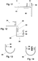
- Figure 13 shows a further embodiment of a separately manufactured and on a corresponding end profile, e.g. the end profile 24 according to FIG. 4c, attachable waste water drainage channel 95, in which the water-carrying channel part is designed in the form of a circular arc.
- a fastening section is provided at the end of the channel part which is circular in cross-section, facing the balcony and which, in the manner described above (see, for example, FIG. 5b), penetrates the narrowed mouth of a groove-like depression provided on a corresponding end profile Strip section 35 and a strip section 38 engaging in the groove-like recess.
- FIG. 14 shows a modification of the waste water drainage channel 95 according to FIG. 13, in which, in addition to the 4c, strip sections 35 and 38 serving for fastening to a corresponding end profile, for example an end profile according to FIG. 4c, an elongated groove-like depression 86 with a narrowed mouth extending in the longitudinal direction of the channel is provided in the channel longitudinal direction and is provided in the manner described above (see FIG. 12) is formed by two rib-like strip sections 87, 88 formed on the waste water drainage channel 95. If two short dirty water drainage channels 95 are to be connected in alignment to form a long channel, the channels can be aligned with one another in a particularly simple manner by inserting a connecting bar described in connection with FIG. 3 into the recesses 86 thereof.
Abstract
Description
Die Erfindung betrifft ein Entwässerungssystem für Balkone, die aus einer Tragplatte und darauf aufgebrachtem Estrich bestehen. Das Entwässerungssystem umfaßt wenigstens ein langgestrecktes Abschlußprofil, das einen vor der Aufbringung des Estrichs auf die Tragplatte des Balkons aufsetzbaren, im wesentlichen ebenflächigen Verankerungsschenkel aufweist, an dessen balkonäußerem Rand sich ein die Tragplatte und den Estrich vor äußeren Witterungseinflüssen schützender Profilabschnitt befindet. Dieser Profilabschnitt setzt sich aus einem etwa die Höhe des Estrichs aufweisenden, im wesentlichen rechtwinklig nach oben vortretenden Profilschenkel und einem schräg nach unten weisenden, die Tragplatte wenigstens teilweise überdeckenden Profilschenkel zusammen.The invention relates to a drainage system for balconies, which consist of a support plate and screed applied thereon. The drainage system comprises at least one elongated end profile, which has an essentially flat anchoring leg that can be placed on the supporting plate of the balcony before the screed is applied, on the outside of the balcony of which there is a profile section that protects the supporting plate and the screed from external weather influences. This profile section is composed of a profile leg which has approximately the height of the screed and essentially protrudes upward at right angles and a profile leg which points obliquely downwards and at least partially covers the support plate.
Ein solches Abschlußprofil ist aus dem deutschen Gebrauchsmuster 90 04 119 bekannt. Dieses Abschlußprofil dient dazu, Schlagregen oder über die Vorderkante des Balkons abfließende Flüssigkeit von der Stirnwand des Balkons fernzuhalten, so daß von dort aus keine Feuchtigkeit in den Estrich oder die Tragplatte eindringen kann.Such an end profile is known from German utility model 90 04 119. This end profile is used to keep driving rain or liquid flowing off the front edge of the balcony away from the front wall of the balcony, so that no moisture can penetrate into the screed or the support plate from there.
Bei mehrstöckigen Wohn- und Geschäftshäusern sind in der Regel mehrere Balkone gleicher Größe senkrecht fluchtend übereinander angeordnet, was zu dem Problem führt, daß von dem Abschlußprofil eines Balkons abtropfendes Schmutzwasser auf den darunterliegenden Balkon trifft und diesen verschmutzen kann. Dies gibt insbesondere bei Wohnhäusern mit Eigentumswohnungen, bei denen in der Regel vertraglich grundsätzlich Beeinträchtigungen des Eigentums durch Nachbarn ausgeschlossen sind, immer wieder Anlaß für Streitigkeiten. Grundsätzlich kann dieses Problem zwar durch Anbringung von - ebenfalls aus dem genannten Gebrauchsmuster bekannten - Regenrinnen vermieden werden, jedoch wird auf diese Lösung aus ästhetischen Gründen oft verzichtet, wie bei einem Stadtrundgang leicht festzustellen ist. Solche herkömmlichen Regenrinnen werden nämlich an einem Balkon aufgrund ihrer Größe und Form als unschön empfunden. Hinzu kommt, daß die aus dem obengenannten Gebrauchsmuster bekannten Regenrinnen bereits bei der Planung des Hauses berücksichtigt werden müssen, da sie ebenso wie das Abschlußprofil im Estrich verankert werden. Das Schmutzproblem tritt jedoch oftmals erst im Laufe der Jahre deutlich hervor.In multi-storey residential and commercial buildings, several balconies of the same size are usually aligned vertically one above the other, which leads to the problem that dirty water dripping from the end profile of a balcony hits the balcony below and can contaminate it. This gives rise repeatedly to disputes, particularly in the case of residential buildings with condominiums, in which contractual impairments of property by neighbors are generally excluded. In principle, this problem can be avoided by installing gutters - also known from the utility model mentioned - but this solution is often dispensed with for aesthetic reasons, as can easily be determined on a city tour. Such conventional gutters are perceived as unattractive on a balcony due to their size and shape. In addition, the gutters known from the above-mentioned utility model must already be taken into account when planning the house, since they are anchored in the screed, just like the end profile. However, the dirt problem often only emerges clearly over the years.
Davon ausgehend liegt der Erfindung die Aufgabe zugrunde, ein Entwässerungssystem für Balkone anzugeben, welches eine Ableitung von Schmutzwasser derart erlaubt, daß ein darunterliegender Balkon - oder auch eine Erdgeschoß-Terrasse - nicht von vom darüberliegenden Balkon abgeführtes Schmutzwasser beeinträchtigt wird, ohne dabei auf herkömmliche Regenrinnen zurückgreifen zu müssen.Based on this, the invention has for its object to provide a drainage system for balconies, which allows a drainage of dirty water such that an underlying balcony - or even a ground floor terrace - is not affected by dirty water discharged from the balcony above, without doing so on conventional gutters to have to fall back.
Diese Aufgabe wird erfindungsgemäß dadurch gelöst, daß bei einem Entwässerungssystem der eingangs genannten Art an dem schräg nach unten weisenden Profilschenkel ein Schmutzwasser-Ablaufkanal vorgesehen ist.This object is achieved in that in a drainage system of the type mentioned in the a wastewater drainage channel is provided at an angle downwards.
Dabei kann der Schmutzwasser-Ablaufkanal im Querschnitt im wesentlichen U-förmig oder auch bogenartig ausgebildet sein.The cross section of the dirty water drainage channel can be essentially U-shaped or also arch-like.
In vorteilhafter Weiterbildung der Erfindung überragt der Schmutzwasser-Ablaufkanal wenigstens eines der beiden Enden des langgestreckten Abschlußprofiles. Damit wird sichergestellt, daß in dem Schmutzwasserkanal eines Balkons zu diesem Ende hin ablaufendes Schmutzwasser ohne weitere Maßnahmen in eine von den unterhalb dieses Balkons liegenden Balkonen oder einer Terrasse abgewandte Richtung abgeleitet wird.In an advantageous development of the invention, the dirty water drainage channel projects beyond at least one of the two ends of the elongated end profile. This ensures that in the dirty water channel of a balcony, waste water running to this end is drained away without further measures in a direction away from the balconies or a terrace below this balcony.
Der Schmutzwasser-Ablaufkanal kann eine dem Balkon abgewandte Durchbrechung aufweisen, an der ein Schmutzwasserspeier vorgesehen ist. Dabei wird unter dem Begriff Schmutzwasserspeier ein kurzes Wasserleitblech oder -rohr verstanden. Die Durchbrechung kann dabei in Profillängsrichtung gesehen an beliebiger Stelle vorgesehen werden, so daß es möglich ist, das Schmutzwasser an einer gewünschten, vorteilhaften Stelle aus dem Schmutzwasser-Ablaufkanal abzuleiten.The dirty water drainage channel can have an opening facing away from the balcony, on which a dirty water spout is provided. The term wastewater spout is understood to mean a short water baffle or pipe. The opening can be provided at any point in the longitudinal direction of the profile, so that it is possible to discharge the dirty water from the dirty water drainage channel at a desired, advantageous point.
Bei einer vorteilhaften Weiterbildung der Erfindung ist der Schmutzwasser-Ablaufkanal integraler Bestandteil des Abschlußprofiles. Dies erlaubt eine kostengünstige Herstellung von Abschlußprofil und Schmutzwasser-Ablaufkanal in einem einzigen Arbeitsgang, z.B. im Strangpreßverfahren.In an advantageous development of the invention, the waste water drainage channel is an integral part of the end profile. This allows a cost-effective production of the end profile and waste water drainage channel in a single operation, e.g. in the extrusion process.
Bei einer anderen vorteilhaften Weiterbildung ist der Schmutzwasser-Ablaufkanal ein gesondert hergestelltes und am Abschlußprofil befestigbarer Bauteil. Eine derartige Ausbildung des Abschlußprofiles erlaubt eine Anbringung des Schmutzwaser-Ablaufkanales auch nach Fertigstellung des Balkones.In another advantageous development, the dirty water drainage channel is a separately manufactured component that can be attached to the end profile. Such a design of the end profile allows attachment of the Dirty water drainage channel even after completion of the balcony.
Eine besonders vorteilhafte Art der Befestigung des Schmutzwasser-Ablaufkanales am Abschlußprofil wird möglich, wenn der schräg nach unten weisende Profilschenkel des Abschlußprofils eine sich in Profillängsrichtung erstreckende langgestreckte nutartige Vertiefung mit verengter Mündung aufweist, in welche dann der Schmutzwasser-Ablaufkanal einschieb- oder einhängbar ist. Durch eine derartige Ausgestaltung von Abschlußprofil und Schmutzwasser-Ablaufkanal wird eine leichte Montage des Schmutzwasser-Ablaufkanales ohne weitere Werkzeuge oder Befestigungsmittel wie z.B. Schrauben oder Nieten möglich.A particularly advantageous way of attaching the waste water drainage channel to the end profile is possible if the obliquely downward profile leg of the end profile has an elongated groove-like depression with a narrowed mouth, into which the dirty water drainage channel can then be inserted or hooked. Such a configuration of the end profile and the waste water drainage channel makes it easy to install the waste water drainage channel without additional tools or fastening means such as e.g. Screws or rivets possible.
Es sind Abschlußprofile bekannt, bei denen sich am verankerungsschenkelabgewandten Rand des schräg nach unten weisenden Profilschenkels ein in eine etwa balkonseitenwandparallele Lage nach unten umgekanteter Profilstreifen anschließt. In vorteilhafter Weiterbildung der Erfindung ist dann an diesem Profilstreifen eine sich in Profillängsrichtung erstreckenden langgestreckten nutartige Vertiefung mit verengter Mündung vorgesehen, in welche der Schmutzwasser-Ablaufkanal einschieb- oder einhängbar ist. Dabei kann die dem schräg nach unten weisenden Profilschenkel abgewandte Stirnfläche des Profilstreifens zum Balkon hin abgeschrägt sein, so daß sich an der balkonabgewandten Seite der Stirnfläche eine Abtropfkante für das Schmutzwasser bildet. Dies hat den Vorteil, daß auch bei nicht eingehängtem oder eingeschobenem Schmutzwasser-Ablaufkanal an dem Abtropfprofil ablaufendes Schmutzwasser immer von dem Balkon fortgeleitet wird.End profiles are known in which a profile strip which is bent downward into a position approximately parallel to the side wall of the balcony is connected at the edge of the profile leg facing away from the anchoring leg. In an advantageous development of the invention, an elongated groove-like depression with a narrowed mouth, which extends in the longitudinal direction of the profile and into which the dirty water drainage channel can be inserted or hooked in, is then provided on this profile strip. The end face of the profile strip facing away from the sloping downward profile leg can be beveled towards the balcony, so that a drip edge for the dirty water forms on the side of the end face facing away from the balcony. This has the advantage that, even when the dirty water drainage channel is not hooked in or pushed in, dirty water running off the drip profile is always carried away from the balcony.
Die genannten verengten Mündungen können von jeweils zwei in parallelem Abstand zur zugeordneten Flachseite am Abschlußprofil angeformten rippenartigen Streifenabschnitten gebildet werden. Dies hat den Vorteil, daß die Vertiefung einfach und kostengünstig - im Falle eines metallischen Abschlußprofils z.B. im Strang-Preßverfahren - hergestellt werden kann, so daß also eine solche Vertiefung nicht nachträglich in das Profil z.B. gefräst werden muß. Auf die vorteilhafte Art der Herstellung wird bei der Figurenbeschreibung noch eingegangen. Darüber hinaus wird mit diesen rippenartigen Streifenabschnitten ein Versteifungseffekt erzielt, welcher das Abschlußprofil sowohl beim Einbau als auch beim Transport versteift und unanfälliger gegen Verwindungen macht. Dies bedeutet, daß solche Abschlußprofile während des Transportes seltener verbogen und dadurch unbrauchbar gemacht werden.The said narrowed mouths can be formed by two rib-like strip sections formed on the end profile at a parallel distance from the associated flat side. This has the advantage that the recess simple and inexpensive - in the case of a metallic end profile, for example in the extrusion process - can be produced, so that such a depression does not have to be subsequently milled into the profile, for example. The advantageous type of manufacture will be discussed in the description of the figures. In addition, a stiffening effect is achieved with these rib-like strip sections, which stiffens the end profile both during installation and during transport and makes it less susceptible to twisting. This means that such end profiles are bent less frequently during transport and are therefore rendered unusable.
Der Versteifungs- und Verstärkungseffekt wirkt sich aber nicht nur beim Transport positiv aus, vielmehr gestaltet sich auch der Einbau vor Ort mit einem steiferen Profil sehr viel einfacher als mit einem flexiblen.The stiffening and reinforcing effect not only has a positive effect during transport, it is also much easier to install on site with a stiffer profile than with a flexible one.
Der Schmutzwasser-Ablaufkanal kann vorteilhaft so ausgebildet werden, daß ein in Kanallängsrichtung verlaufender Befestigungsabschnitt vorgesehen ist, der in die nutartige Vertiefung des Abschlußprofiles einschieb- oder einhängbar ist und der ein zum Querschnitt der nutartigen Vertiefung zumindest partiell komplementären Querschnitt besitzt. Dabei kann der Befestigungsabschnitt einen die der nutartigen Vertiefung abgewandte Seite der verengten Mündung überdeckenden Streifenabschnitt, einen die Mündung durchsetzenden Streifenabschnitt und einen am vertiefungsseitigen Ende des die Mündung durchsetzenden Streifenabschnittes angesetzten, etwa parallel zu der eine Innenfläche der Vertiefung bildenden Flachseite des Abschlußprofils verlaufenden Streifenabschnitt aufweisen.The dirty water drainage channel can advantageously be designed such that a fastening section running in the longitudinal direction of the channel is provided, which can be inserted or hooked into the groove-like recess of the end profile and which has a cross section which is at least partially complementary to the cross section of the groove-like recess. The fastening section can have a strip section covering the side of the narrowed mouth facing away from the groove-like recess, a strip section penetrating the mouth and a strip section attached to the recess-side end of the strip section penetrating the mouth, approximately parallel to the strip section which forms an inner surface of the recess and forms the end profile.
Bei dem so ausgebildeten Schmutzwasser-Ablaufkanal ist es in vorteilhafter Weiterbildung möglich, die Höhe des parallel zu der der Mündung gegenüberliegenden Innenfläche der Vertiefung umgekanteten Streifenabschnittes maximal gleich der Breite der Mündung der nutartigen Vertiefung zu bemessen, so daß der Schmutzwasser-Ablaufkanal an beliebiger Stelle in das Abschlußprofil eingehängt werden kann. Dabei kann das Einhängen dadurch erleichtert werden, daß die vom Ablaufkanal weisende Flanke des in die zu der eine Innenfläche der Vertiefung bildenden Flachseite des Abschlußprofils parallele Lage umgekanteten Streifenabschnitts wenigstens über einen Teil ihrer Höhe zu dem die Mündung durchsetzenden Streifenabschnitts hin abgeschrägt ist.In the waste water drainage channel designed in this way, it is possible in an advantageous further development that the height of the strip section folded over parallel to the inner surface of the depression opposite the mouth is maximally the same to measure the width of the mouth of the groove-like recess, so that the dirty water drainage channel can be hung anywhere in the end profile. In this case, the attachment can be facilitated in that the flank of the strip section pointing from the drainage channel to the flat section of the end profile which is parallel to the flat surface of the recess forming an inner surface of the recess is beveled at least over part of its height towards the strip section passing through the mouth.
Zur Ableitung des Schmutzwassers aus dem Schmutzwasser-Ablaufkanal kann an wenigstens einem Ende des Kanales ein Schmutzwasserspeier angeordnet werden. Dieser Speier leitet das Schmutzwasser in eine beliebige Richtung ab. Alternativ oder ergänzend ist es auch möglich, den Schmutzwasser-Ablaufkanal in an sich bekannter Weise an ein Fallrohr anzuschließen, z. B. durch Aufschieben einer Fallrohranschluß-Schiebemuffe auf ein Ende eines Schmutzwasser-Ablaufkanales.To discharge the dirty water from the dirty water drainage channel, a dirty water spout can be arranged at at least one end of the channel. This spout drains the dirty water in any direction. Alternatively or in addition, it is also possible to connect the waste water drainage channel to a downpipe in a manner known per se, e.g. B. by pushing a downpipe connection sliding sleeve on one end of a dirty water drain channel.
In manchen Anwendungsfällen eines erfindungsgemäßen Erfindungssystems kann es vorteilhaft sein, den Schmutzwasser-Ablaufkanal an wenigstens einem Ende zu verschließen. Dazu kann eine gesondert hergestellte Abschlußkappe an einem Ende des Schmutzwasserkanals aufgeschoben werden, welche den Kanal an diesem Ende seitlich und nach unten wasserdicht abschließt.In some applications of an inventive system, it can be advantageous to close the waste water drainage channel at at least one end. For this purpose, a separately produced end cap can be slid onto one end of the sewage channel, which closes the channel at this end in a watertight manner at the side and downwards.
In vorteilhafter Weiterbildung weist das Entwässerungssystem wenigstens ein weiteres langgestrecktes Abschlußprofil (Zuführprofil) für die seitlichen Balkonränder auf, welches einen im wesentlichen ebenflächigen Verankerungsschenkel aufweist, an welchen balkonrandseitig ein in oder über dem Schmutzwasser-Ablaufkanal mündender Schmutzwasser-Zuführkanal angeordnet ist. Mittels eines solchen Zuführprofiles kann das über die seitlichen Ränder eines Balkons abströmende Schmutzwasser aufgefangen und dem stirnseitig vorgesehenen Schmutzwasser-Ablaufkanal zugeführt werden.In an advantageous further development, the drainage system has at least one further elongated end profile (feed profile) for the lateral balcony edges, which has an essentially flat anchoring leg, on the balcony edge of which a waste water feed channel opening into or above the waste water drainage channel is arranged. With such a feed profile, this can be done over the side edges of a balcony outflowing waste water is collected and fed to the waste water drainage channel provided on the front.
Je nach Art und Ausgestaltung des Gesamtsystems und der damit zu entwässernden Balkone kann es zweckmäßig sein, Schmutzwasser-Zuführkanal und Schmutzwasser-Ablaufkanal über Eckverbindungselemente zu verbinden. Solche Eckverbindungselemente können aus Metall oder Kunststoff hergestellt sein, wobei durch Verwendung geigneter, eine gewisse Elastizität aufweisender Kunststoffe vorteilhaft Längenveränderungen der in der Regel metallischen Schmutzwasser-Ablaufkanäle bzw. -Zuführkanäle aufgrund thermischer Ausdehnung ausgeglichen werden können.Depending on the type and design of the overall system and the balconies to be drained therewith, it may be expedient to connect the dirty water supply duct and the dirty water discharge duct via corner connecting elements. Such corner connecting elements can be made of metal or plastic, whereby by using suitable plastics with a certain elasticity, length changes of the generally metallic waste water drainage channels or supply channels due to thermal expansion can advantageously be compensated for.
In vorteilhafter Weiterbildung weist das Zuführprofil einen den Estrich wenigstens zum Teil überdeckenden Profilschenkel auf. Dieser Profilschenkel schützt die Tragplatte vor äußeren Witterungseinflüssen.In an advantageous development, the feed profile has a profile leg that at least partially covers the screed. This profile leg protects the support plate from external weather influences.
Um eine größere Kontaktfläche zur Verfügung zu stellen und damit die Haftung des z.B. mittels Fliesenklebers auf dem Estrich zu verankernden Verankerungsschenkel des Zuführprofiles zu verbessern, kann in vorteilhafter Weiterbildung die dem Estrich zugewandte Unterseite des Verankerungsschenkels zumindest abschnittsweise mit oberflächenvergrößernden Ausnehmungen versehen werden.In order to provide a larger contact area and thus the liability of e.g. In order to improve the anchoring leg of the feed profile to be anchored on the screed by means of tile adhesive, the underside of the anchoring leg facing the screed can be provided, at least in sections, with surface-enlarging recesses.
In solchen Fällen, in denen beim Aufbau des Balkones und dem Verlegen des Entwässerungssystems noch keine genauen Werte über den Schmutzwasseranfall vorliegen, wird zweckmäßig ein vorteilhaft weitergebildetes Entwässerungssystem verwendet, bei welchem an dem schräg nach unten weisenden Profilschenkel des Abschlußprofils ein im wesentlichen senkrecht nach unten weisender Profilstreifen vorgesehen ist, der eine langgestreckte Vertiefung mit verengter Mündung besitzt, an dem eine langgestreckte im wesentlichen streifenförmige Führungsblende mittels einer zu der verengten Mündung zumindest partiell komplementären Befestigungsabschnitts an dem Abschlußprofil befestigbar ist. An einer solchen Führungsblende kann dann ein Schmutzwasser-Ablaufkanal befestigbar sein. Erweist sich nun die Verschmutzung eines unter dem Balkon gelegenen Arials nicht als kritisch, so wird anstelle eines Schmutzwasser-Abführkanals lediglich die langgestreckte streifenförmige Schmutzwasser-Führungsblende angebracht. Erweist sich die Verschmutzung jedoch als kritisch, so kann an der Führungsblende jederzeit ein Schmutzwasser-Ablaufkanal befestigt werden.In such cases, in which no exact values about the amount of dirty water are available when setting up the balcony and laying the drainage system, an advantageously developed drainage system is expediently used, in which an essentially vertically downward-pointing profile leg of the end profile points downward Profile strip is provided, which has an elongated recess with a narrowed mouth, on which an elongated substantially strip-shaped guide screen by means of a narrowed to the Mouth at least partially complementary fastening section can be fastened to the end profile. A waste water drainage channel can then be fastened to such a guide screen. If the contamination of an arial located under the balcony does not turn out to be critical, then instead of a dirty water drainage channel, only the elongated strip-shaped dirty water guide screen is attached. However, if the contamination proves to be critical, a waste water drainage channel can be attached to the guide panel at any time.
In vorteilhafter Weiterbildung der Erfindung wird dabei dieser Schmutzwasser-Ablaufkanal an der Führungsblende mittels wenigstens einer Schrauben-Mutter-Verbindung festgeklemmt, wobei in der Führungsblende und im Schmutzwasser-Ablaufkanal je eine Öffnung für die Schraube vorgesehen ist, wobei eine der Öffnungen einen im wesentlichen kreisförmigen Querschnitt besitzt, während die andere als Langloch derart ausgebildet ist, daß der Schmutzwasser-Ablaufkanal höhen- und/oder neigungsveränderlich an der Führungsblende befestigbar ist.In an advantageous development of the invention, this dirty water drain channel is clamped to the guide screen by means of at least one screw-nut connection, an opening for the screw being provided in the guide screen and in the dirty water drain channel, one of the openings being essentially circular Cross-section has, while the other is designed as an elongated hole in such a way that the waste water drainage channel can be attached to the guide screen in a manner that is variable in height and / or inclination.
Weitere Einzelheiten und Vorteile der Erfindung ergeben sich aus der nachfolgenden Figurenbeschreibung in Verbindung mit den lediglich Ausführungsbeispiele zeigenden Zeichnungen. Es zeigen:
- Fig. 1
- eine Draufsicht auf einen mit Fliesen verlegten Balkon, der von einer Hauswand vortritt;
- Fig. 2
- eine perspektivische Darstellung eines Abschnittes eines auf der gebäudeabgewandten vorderen Stirnfläche des in Fig. 1 gezeigten Balkons vorgesehenen Abschlußprofils, bei dem der Schmutzwasser-Ablaufkanal integraler Bestandteil ist;
- Fig. 3
- die Seitenansicht einer Abwandlung des Abschlußprofiles nach Fig. 2;
- Fig. 4a, b, c
- ein erfindungsgemäßes Abschlußprofil und einen gesondert hergestellten Schmutzwasser-Ablaufkanal im unmontierten und im montierten Zustand in Seitenansicht;
- Fig. 5a, b
- eine Abwandlung eines Abschlußprofiles und eines erfindungsgemäßen Schmutzwasser-Ablaufkanals gemäß den Fig. 4a und 4b in Seitenansicht;
- Fig. 6
- eine perspektivische Darstellung eines Schmutzwasserspeiers, welcher für eine dem Balkon abgewandte Durchbrechung des Schmutzwasser-Ablaufkanales vorgesehen ist;
- Fig. 7
- eine perspektivische Darstellung eines an einem Ende des Schmutzwasser-Ablaufkanals anzuordnenden Schmutzwasserspeiers;
- Fig. 8
- eine Schnittansicht durch eine seitliche Begrenzung des Balkons gemäß Fig. 1, an welcher ein erfindungsgemäßes Zuführ-Profil vorgesehen ist;
- Fig. 9
- eine Seitenansicht eines Abschlußprofils, welches anstelle eines Schmutzwasser-Ablaufkanals mit einer Schmutzwasser-Führungsblende versehen ist;
- Fig.10
- eine Seitenansicht eines Schmutzwasser-Ablaufkanales, welcher an der Schmutzwasser-Führungsblende gemäß Fig. 9 montierbar ist;
- Fig. 11
- eine Seitenansicht eines Schmutzwasser-Zuführprofiles, bei welchem an der Unterseite oberflächenvergrößernde Ausnehmungen vorgesehen sind;
- Fig. 12
- eine Abwandlung eines Abschlußprofiles und eines erfindungsgemäßen Schmutzwasser-Ablaufkanales gemäß Fig. 4c in Seitenansicht;
- Fig. 13
- eine Seitenansicht eines gesondert hergestellten Schmutzwasser-Ablaufkanales, bei welchem der wasserleitende Kanalbereich im Querschnitt kreisbogenförmig ausgebildet ist, und
- Fig. 14
- eine Abwandlung eines gesondert hergestellten Schmutzwasser-Ablaufkanales gemäß Fig 13, wobei auf der Kanalinnenseite eine in Kanallängsrichtung verlaufende langgestreckte nutartige Vertiefung vorgesehen ist.
- Fig. 1
- a plan view of a tiled balcony that emerges from a house wall;
- Fig. 2
- a perspective view of a portion of an end profile provided on the front face of the balcony shown in FIG. 1 facing away from the building, in which the dirty water drainage channel is an integral part;
- Fig. 3
- the side view of a modification of the end profile of FIG. 2;
- 4a, b, c
- an end profile according to the invention and a separately produced waste water drain channel in the unassembled and in the assembled state in a side view;
- 5a, b
- a modification of an end profile and a dirty water drainage channel according to Figures 4a and 4b in side view.
- Fig. 6
- a perspective view of a dirty water spout, which is provided for an opening facing away from the balcony of the dirty water drainage channel;
- Fig. 7
- a perspective view of a dirty water spout to be arranged at one end of the dirty water drainage channel;
- Fig. 8
- a sectional view through a lateral boundary of the balcony of Figure 1, on which an inventive feed profile is provided.
- Fig. 9
- a side view of an end profile, which is provided instead of a dirty water drainage channel with a dirty water guide screen;
- Fig. 10
- a side view of a waste water drainage channel, which can be mounted on the waste water guide panel according to FIG. 9;
- Fig. 11
- a side view of a dirty water supply profile, in which surface-enlarging recesses are provided on the underside;
- Fig. 12
- a modification of an end profile and a dirty water drainage channel according to FIG 4c in side view.
- Fig. 13
- a side view of a separately produced waste water drainage channel, in which the water-conducting channel area is formed in the shape of a circular arc in cross section, and
- Fig. 14
- a modification of a separately manufactured waste water drainage channel according to FIG. 13, an elongated groove-like depression extending in the longitudinal direction of the channel being provided on the inside of the channel.
Fig. 1 zeigt eine Draufsicht auf einen mit Fliesen 1 verlegten Balkon 2, der von einer Hauswand 3 vortritt. Die Hauswand 3 weist dabei eine Durchbrechung für eine Tür zu dem Balkon 2 auf. Die der Hauswand 3 abgewandte Stirnseite des Balkons 2 wurde mit einem Abschlußprofil 4 versehen, wobei an dem Abschlußprofil 4 ein Schmutzwasser-Ablaufkanal 5 vorgesehen ist. An dem sich rechtwinklig von der Hauswand 3 erstreckenden Seite des Balkons 2 wurde je ein Zuführprofil 6 vorgesehen, dessen Schmutzwasser-Zuführkanal in dem Schmutzwasser-Ablaufkanal 5 mündet. Der Schmutzwasser-Ablaufkanal 5 mündet dabei über den beiden Enden des langgestreckten Abschlußprofiles 4. Anfallendes Schmutzwasser kann nun in dem Schmutzwasser-Ablaufkanal 5 abfließen, ohne daß ein unter diesem Balkon gelegener Balkon verschmutzt würde. Das an den rechtwinklig zur Häuserfront verlaufenden Seitenwände des Balkons 2 anfallende Schmutzwasser wird von den Zuführprofilen 6 dem Schmutzwasser-Ablaufkanal zugeführt, der bei diesem Ausführungsbeispiel ein integraler Bestandteil des in der Fig. 2 im Schnitt gezeigten Abschlußprofiles 4 ist. Während bei diesem Ausführungsbeispiel die Schmutzwasser-Zuführkanäle im Schmutzwasser-Ablaufkanal 5 in der beschriebenen Weise münden, ist es alternativ auch möglich, die Kanäle mittels geeigneter Eckverbindungselemente zu verbinden, welche z.B. in die miteinander zu verbindenden Kanäle eingelegt oder auf diese Kanäle aufgesteckt bzw. aufgeschoben werden können, wobei dann durch Verwendung geeigneter, an sich bekannter Werkstoffe für die Herstellung der Eckverbindungselemente auch eventuell auftretende Längenveränderungen der Kanäle aufgrund thermischer Ausdehnung ausgeglichen werden können.Fig. 1 shows a plan view of a balcony 2 laid with
In der Fig. 2 ist ein langgestrecktes Abschlußprofil 4 im Querschnitt dargestellt, das einen vor der Aufbringung von Estrich auf die Tragplatte des Balkones aufsetzbaren, im wesentlichen ebenflächigen Verankerungsschenkel 7 aufweist, an dessen balkonäußerem Rand sich ein in der späteren bestimmungsgemäßen Einbaulage die Tragplatte und den Estrich vor äußeren Witterungseinflüssen schützender Profilabschnitt befindet, der sich aus einem im wesentlichen rechtwinklig nach oben vortretenden Profilschenkel 8 und einem schräg nach unten weisenden Profilschenkel 9 zusammensetzt. An dem schräg nach unten weisenden Profilschenkel 9 ist ein Schmutzwasser-Ablaufkanal 5 vorgesehen. In diesem Ausführungsbeispiel ist der Schmutzwasser-Ablaufkanal 5 integraler Bestandteil des Abschlußprofiles 4 und im wesentlichen U-förmig ausgebildet. Er besteht aus einem am verankerungsschenkelabgewandten Rand des schräg nach unten geneigten Profilschenkels 9 in eine etwa stirnwandparallele Lage nach unten umgekanteten Profilstreifen 10, einem zur balkonabgewandten Seite rechtwinklig von diesem umgekanteten und den Boden des Schmutzwasser-Ablaufkanales 5 bildenden Profilstreifen 11 und einem vom Boden des Kanales rechtwinklig nach oben umgekanteten Profilstreifen 12.In Fig. 2, an
Am oberen Rand des nach oben vortretenden Profilschenkels 8 ist ein sich rückwärts über den Verankerungsschenkel 7 erstreckender, umgekanteter Profilstreifen 13 angesetzt, dessen Breite geringer ist als die Breite des Verankerungsschenkels. Dieser rückwärts weisende Profilstreifen verhindert das Eindringen von Flüssigkeit in den stirnwandnahen Bereich des Estrichs. Außerdem versteift der Profilstreifen 13 das Profil 4 in seinem oberen Bereich gegen ungewollte Verformungen.At the upper edge of the upwardly projecting
An dem über dem Verankerungsschenkel 7 liegenden freien Rand des Profilstreifens 13 ist zusätzlich ein schmaler, nach unten zum Verankerungsschenkel 7 gerichteter Streifenabschnitt 14 vorgesehen, welcher das Abschlußprofil zusätzlich zur Verankerung durch den Verankerungsschenkel im Estrich verankert und außerdem eine weitere Versteifung zur Stabilisierung des Abschlußprofils bewirkt.On the free edge of the
Bei dem Ausführungsbeispiel der Fig. 2 weist der Verankerungsschenkel 7 eine Vielzahl von - im dargestellten Fall - quadratischen oder rechteckigen Durchbrechungen 15 auf. Der durch die Durchbrechungen 15 durchtretende und sich innerhalb der Durchbrechungen 15 mit der Oberseite der Tragplatte haftend verbindende Estrich verankert das Abschlußprofil 4 nach seiner Aushärtung form- und/oder kraftschlüssig auf der Tragplatte. Es sei betont, daß die Durchbrechungen auch in anderer Form als der gezeigten quadratischen oder rechtwinkligen Form vorgesehen werden können, also insbesondere dreieckiger oder sonstwie polygonaler, runder oder abgerundeter Form. Dabei läßt sich ein solches Profil einfach und kostengünstig aus einer geeigneten Aluminium-Legierung im Strang-Preß-Verfahren herstellen. Grundsätzlich können vergleichbare Profile aber auch in anderer Weise und aus anderen metallischen Materialien oder Kunststoffen hergestellt werden. Als Beispiel sei nur auf die Möglichkeit der Herstellung von Teilprofilen im Stanz-Preß-Verfahren aus Metallblech, z.B. korrisionsfestem Stahlblech hingewiesen, die dann durch Verbindung bestimmter Profilschenkel durch Verschweißen, Nieten o.dgl. zu einem dem dargestellten Profil 4 entsprechenden Profil verbunden werden.In the exemplary embodiment in FIG. 2, the anchoring
Die Fig. 3 zeigt ein leicht abgewandeltes Abschlußprofil 4, bei welchem die dem Profilschenkel 8 abgewandte Außenflanke des Streifenabschnitts 16 abgeschrägt ist. Dadurch werden beim späteren Auftragen des fließfähigen Estrichs stömungsgünstige Bedingungen für ein Umströmen dieses Streifenabschnittes 10 von dem Estrich geschaffen, ohne dabei jedoch die Versteifungswirkung des Streifenabschnittes 16 auf das gesamte Profil 4 zu beeinträchtigen. Ferner sind bei diesem Ausführungsbeispiel des Abschlußprofils 4 zwei langgestreckte nutartige Vertiefungen 17, 18 vorgesehen, in welche sich zur Verbindung zweier Profile Verbindungselemente gemäß der deutschen Patentanmeldung P 44 43 634.3 einschieben lassen. Die langgestreckte nutartige Vertiefung 17 ist dabei auf der in der bestimmungsgemäßen Einbaulage dem Estrich zugewandten Flachseite des Profilschenkels 8 vorgesehen, während die nutartige Vertiefung 18 auf der in der bestimmungsgemäßen Einbaulage der Tragplatte zugewandten Seite des die Tragplatte vor äußeren Witterungseinflüssen schützenden Profilabschnitts vorgesehen ist.3 shows a slightly modified
In den Figuren 4a, b und c ist ein weiteres Ausführungsbeispiel eines erfindungsgemäßen Abschlußprofiles 24 und eines Schmutzwasser-Ablaufkanales 25 gezeigt. Bei diesem Ausführungsbeispiel ist der Schmutzwasser-Ablaufkanal 25 ein gesondert hergestellter und am Abschlußprofil 24 befestigbarer Bauteil. Das Abschlußprofil 24 besteht aus dem Verankerungsschenkel 27, an dessen balkonäußerem Rand sich der im wesentlichen rechtwinklig nach oben vortretende Profilschenkel 28 sowie der schräg nach unten weisende Profilschenkel 29 angesetzt ist.FIGS. 4a, b and c show a further exemplary embodiment of an
Am verankerungsschenkelabgewandten Rand des schräg nach unten weisenden Profilschenkels 29 schließt sich ein in eine zur Balkon-Seitenwand parallele Lage nach unten umgekanteter Profilstreifen 30 an. Zur Verbindung des Schmutzwasser-Ablaufkanales 25 mit dem Abschlußprofil 24 weist der Profilstreifen 30 eine sich in Profil-Längsrichtung erstreckende langgestreckte nutartige Vertiefung 31 mit verengter Mündung auf, die von zwei in gleichem Abstand parallel zur dem Balkon zugewandten Seite des Profilstreifens 30 am Abschlußprofil 24 angeformten rippenartigen Streifenabschnitten 32, 33 gebildet wird. Der zwischen der dem Balkon zugewandten Flachseite des Profilstreifens 30 und der verengten Mündung liegende Querschnitt der langgestreckten nutartigen Vertiefung 31 hat dabei die Form eines Rechtecks.On the edge of the
Der Schmutzwasser-Ablaufkanal 25 weist einen in Kanal-Längsrichtung verlaufenden Befestigungsabschnitt auf, der sich aus einem die der nutartigen Vertiefung abgewandte Seite der verengten Mündung überdeckenden Streifenabschnitt 34, einem die Mündung durchsetzenden Streifenabschnitt 35 und einem am vertiefungsseitigen Ende des die Mündung durchsetzenden Streifenabschnitts 35 angesetzten, in der bestimmungsgemäßen Einbaulage etwa parallel zu dem dann parallel zur Tragplatte verlaufenden Profilstreifen 30 verlaufenden Streifenabschnitt 36 zusammensetzt. In der Fig. 4c ist das Abschlußprofil 24 gezeigt, wobei der Schmutzwasser-Ablaufkanal 25 mit seinem Befestigungsabschnitt von der Seite aus in die dafür vorgesehene nutartige Vertiefung am Abschlußprofil 24 eingeschoben wurde.The dirty
In den Figuren 5a und 5b sind leicht abgewandelte Ausführungsbeispiele eines Abschlußprofils 24 und eines Schmutzwasser-Ablaufkanales 25 gemäß den Figuren 4a und 4b gezeigt. Dabei besitzt das abgewandelte Abschlußprofil 24 am dem Verankerungsschenkel 27 abgewandten Rand des später den Estrich abdeckenden, rechtwinklig nach oben verlaufenden Profilschenkels 28 einen in eine zum Verankerungsschenkel 27 parallele Lage umgekanteten Profilstreifen 37.FIGS. 5a and 5b show slightly modified exemplary embodiments of an
Der Schmutzwasser-Ablaufkanal 25 weist bei diesen Ausführungsbeispielen einen Befestigungsabschnitt auf, bei dem die Höhe des parallel zu der der Mündung gegenüberliegenden Innenfläche der Vertiefung 31 umgekanteten Streifenabschnitts 38 der Breite der Mündung der nutartigen Vertiefung 31 des Abschlußprofiles 24 entspricht und der vom Streifenabschnitt 35 nach unten umgekantet ist. Diese Ausgestaltung gewährleistet, daß der Schmutzwasser-Ablaufkanal 25 nicht nur von einem Ende des Abschlußprofils 24 her in die nutartige Vertiefung 31 eingeschoben, sondern auch an beliebiger Stelle in die verengte Mündung eingehängt und dann durch Absenken in der Vertiefung verriegelt werden kann. Das Einhängen wird dabei dadurch erleichtert, daß die vom Ablaufkanal wegweisende Flanke des Streifenabschnitts 38 in der in Fig. 5 erkennbaren Weise über einen Teil ihrer Höhe zu dem die Mündung durchsetzenden Streifenabschnitt 35 hin abgeschrägt ist. Bei diesem Ausführungsbeispiel eines erfindungsgemäßen Abschlußprofiles ist die später dem Schmutzwasser-Ablaufkanal zugewandte Stirnfläche des Profilstreifens 30 derart abgeschrägt, daß sich an der balkonabgewandten Seite der Stirnfläche eine Abtropfkante für das Schmutzwasser bildet. Dies hat den Vorteil, daß auch bei nichteingehängtem oder eingeschobenem Schmutzwasser-Ablaufkanal an dem Abschlußprofil ablaufendes Schmutzwasser von dem Balkon fortgeleitet wird.In these exemplary embodiments, the dirty
Die Figur 6 zeigt einen Schmutzwasserspeier 41, der zur Anbringung an einer dem Balkon abgewandten Durchbrechung im Schmutzwasser-Ablaufkanal vorgesehen ist. Vorteilhaft wird ein solcher Schmutzwasserspeier an der Stoßkante zweier fluchtend miteinander zu verbindenden Schmutzwasser-Ablaufkanäle vorgesehen. Der Schmutzwasserspeier besteht aus einem etwa in der Mitte eines Befestigungsprofils angesetzten Wasserleitblech 42 mit seitlich umgekanteten Wänden 43, 44.FIG. 6 shows a
Das Befestigungsprofil besteht aus fünf jeweils rechtwinklig zueinander umgekanteten Profilstreifen 46, 47, 48, 49, 50, die ein nach oben offenes im wesentlichen U-förmiges Profil bilden, welches eine zu dem Querschnitt eines zugeordneten Schmutzwasser-Ablaufkanales zumindest partiell komplementären Querschnitt aufweist. An der Stoßkante zweier miteinander zu verbindender Schmutzwasser-Ablaufkanäle kann nun ein solcher Schmutzwasserspeier 41 vorteilhaft durch einfaches Aufrasten über der Stoßstelle der gesonderten Schmutzwasser-Ablaufkanäle vorgesehen werden. Bei integraler Herstellung des Schmutzwasser-Ablaufkanals mit dem eigentlichen Abschlußprofil kann das Befestigungsprofil auch ins Innere des Schmutzwasser-Ablaufkanals eingeschoben werden. Die balkonabgewandten vorderen Wände der Schmutzwasser-Ablaufkanäle müssen dabei im Bereich der Stoßstelle ausgeschnitten werden, damit anfallendes Schmutzwasser über den Speier 41 abgeführt werden kann.The fastening profile consists of five profile strips 46, 47, 48, 49, 50, each folded at right angles to one another, which form an essentially U-shaped profile which is open at the top and which has a cross section which is at least partially complementary to the cross section of an assigned waste water drainage channel. Such a
Einen zur Abringung an einem Ende eines Schmutzwasser-Ablaufkanales vorgesehenen Schmutzwasserspeier 51 zeigt die Fig. 7. Dieser besteht aus einem an einem Ende eines Befestigungsprofiles angebrachten Wasserleitblech 52 mit seitlich nach oben umgekanteten Blechstreifen 53, 54, die seitliche Begrenzungswände für den Wasserlauf bilden. Das Befestigungsprofil ist dabei in gleicher Weise wie das Befestigungsprofil des in Fig. 6 gezeigten Schmutzwasserspeiers aufgebaut. Ein solcher Schmutzwasserspeier 51 läßt sich vorteilhaft an einem Ende eines erfindungsgemäßen Schmutzwasser-Ablaufkanals durch einfaches Einschieben in oder Aufschieben auf den Kanal anbringen, wodurch dann Schmutzwasser in eine gewünschte Richtung abgeleitet wird.FIG. 7 shows a
Die Fig. 8 zeigt einen Schnitt durch eine Seite des Balkons gemäß Fig. 1, an welcher ein erfindungsgemäßes Zuführprofil 6 vorgesehen ist. Das Zuführprofil 6 weist einen im wesentlichen ebenflächigen Verankerungsschenkel 61 auf, an dessen balkonäußerem Rand sich ein rechtwinklig nach oben umgekanteter Profilabschnitt 62 befindet, an dessen balkonabgewandter Seite ein Schmutzwasser-Zuführkanal 63 angeordnet ist.FIG. 8 shows a section through one side of the balcony according to FIG. 1, on which a
Bei diesem Ausführungsbeispiel wird der Schmutzwasser-Zuführkanal 63 von dem rechtwinklig nach oben umgekanteten Profilabschnitt 62, der Verlängerung des Verankerungsschenkels 61 zur Balkon-Außenseite und einem parallel zu dem Profilabschnitt 62 laufenden, am balkonäußeren Rand der Verlängerung des Verankerungsschenkels 61 angesetzten Profilschenkel 64 gebildet. Der Schmutzwasser-Zuführkanal 63 hat also ein U-förmiges Profil. Der Profilschenkel 64 ist dabei derart an der Verlängerung des Verankerungsschenkels 61 angesetzt, daß er nicht nur zum Teil rechtwinklig nach oben verläuft und so eine Außenwand des Schmutzwasser-Zuführkanals 63 bildet, sondern auch rechtwinklig nach unten verläuft und so den Estrich 65 ganz, und die Tragplatte 66 des Balkons zumindest zum Teil überdeckt und sie somit vor äußeren Witterungseinflüssen schützt.In this exemplary embodiment, the dirty
Der Verankerungsschenkel 61 ist auf dem Estrich 65 aufgesetzt. Zur Abdichtung des Estrichs 65 ist bei dem gezeigten Beispiel eine Abdichtfolie 67 auf dem Estrich und dem Verankerungsschenkel 61 verlegt. Auf dieser Abdichtfolie 67 wurden sodann ein Fliesenkleber 68 aufgebracht und die Fliesen 1 verlegt. Im Übergangsbereich zwischen der den Boden des SchmutzwasserZuführkanals 63 bildenden Verlängerung des Verankerungsschenkels 61 und dem äußeren Profilschenkel 64 wird zweckmäßig eine abgeschrägte Hohlkehle 69 ausgebildet. Das über den Zuführkanal 63 abgeführte Wasser strömt dann mit Abstand vom äußeren Profilschenkel, so daß es im Übergangsbereich zum Schmutzwasser-Abführkanal 5 bzw. 25 des stirnseitigen Abschlußprofils 4 bzw. 24 nicht über den Rand des am Verankerungsprofil 61 angesetzten nach unten weisenden Abschnitt des Profilschenkels 64 abströmt. D.h. der Schmutzwasser-Abführkanal des Abschlußprofils 4 bzw. 24 muß nicht über das Zuführprofil 6 nach außen überstehen.The anchoring
In solchen Fällen, in denen die Verschmutzung eines unter einem Balkon vorgesehenen Areals eines Gebäudes nicht kritisch ist, weil der Balkon sich beispielsweise lediglich über den hausnahen Bereich des Gartens erstreckt, kann es sinnvoll sein, anstelle eines Schmutzwasser-Abführkanals 25 am stirnseitigen Abschlußprofil 24 lediglich eine langgestreckte streifenförmige Schmutzwasser-Führungsblende 70 anzubringen, wie dies in Fig. 9 veranschaulicht ist. Diese Führungsblende 70 ist in bezug auf die sie in der langgestreckten nutartigen Vertiefung des Abschlußprofils 24 halternden Mittel entsprechend dem Schmutzwasser-Abführkanal 25 gemäß Fig. 5b ausgebildet, so daß sie einfach nachträglich am unteren Profilstreifen 30 anbringbar ist. Dabei sollte die Blende 70 in der Höhe so bemessen werden, daß ihr unterer freier Rand noch bis unter die Unterkante der Balkon-Tragplatte reicht. Dadurch wird dann sichergestellt, daß auch bei starker Windeinwirkung das über das Abschlußprofil 24 ablaufende Schmutzwasser an der unteren Randkante der Blende 70 abtropft und nicht etwa zur Balkon-Stirnfläche geführt wird und dort die Tragplatte bzw. den Estrich durchnäßt.In such cases, in which the contamination of an area of a building provided under a balcony is not critical, for example because the balcony only extends over the area of the garden close to the house, it may be sensible to merely place a waste
Zusätzlich bietet es sich an, die sichtbare Vorderseite der Blende 70 mit einer dekorativen Oberflächenbeschichtung zu versehen, welche also auch eine Verbesserung des Aussehens eines im Bereich der Balkone mit solchen Blenden versehenen Gebäudes ermöglicht. Erweist sich dann die Verschmutzung doch als kritisch, z.B. weil das unter dem Balkon vorgesehene Areal plötzlich genutzt werden soll, so kann an der Führungsblende 70 ein Schmutzwasser-Ablaufkanal 25, wie ihn die Fig. 10 zeigt, angebracht werden. Dieser wird zweckmäßig mittels einer hier nicht gezeigten Schrauben-Mutter-Verbindung an der Führungsblende 70 festgeklemmt. Dazu sind in dem dem Balkon zugewandten Schenkel des Schmutzwasser-Ablaufkanals 25, der beim hier gezeigten Ausführungsbeispiel einen U-förmigen Querschnitt besitzt und aus drei langgestreckten Profilschenkeln besteht, und in der Führungsblende 70 die durch die punktierten Linien angedeuteten Öffnungen 82, 84 vorgesehen, wobei die Öffnung 84 in dem Schmutzwasser-Ablaufkanal 25 einen kreisförmigen Querschnitt aufweist, während die Öffnung 82 in der Führungsblende 70 als Langloch ausgebildet ist.In addition, it is advisable to provide the visible front of the
Der tiefste Punkt der Öffnung 84 im Schmutzwasser-Ablaufkanal 25 liegt dabei oberhalb der Oberkante des die eine Schmutzwasser-Ablaufkanal-Außenwand bildenden, dem Balkon abgewandten Profilschenkels, so daß auch ohne spezielle Abdichtung der Öffnung 84 gewährleistet ist, daß auch bei großem Schmutzwasseranfall Schmutzwasser stets vom Balkon weggeleitet wird. Steckt man durch diese Öffnungen eine Schraube und klemmt Schmutzwasser-Ablaufkanal 25 und Führungsblende 70 durch Anziehen einer am Ende dieser Schraube aufgesetzten Mutter fest, so kann durch die Ausbildung der einen Öffnung 82 als Langloch die Neigung des Schmutzwasser-Ablaufkanals in gewünschter Weise verändert werden. Es sei an dieser Stelle betont, daß dabei natürlich das Langloch auch in dem Schmutzwasser-Ablaufkanal vorgesehen werden kann und daß auch beide Öffnungen 82, 84 als Langlöcher ausgebildet sein können, welche dann vorteilhaft hinsichtlich ihrer Längserstreckung winkelversetzt angeordnet werden.The lowest point of the
Die Fig. 11 zeigt ein erfindungsgemäßes Schmutzwasser-Zuführprofil 6, bei welchem der Verankerungsschenkel 61 an seiner dem Estrich zugewandten Unterseite abschnittsweise oberflächenvergrößernde Ausnehmungen 80 aufweist. Diese Ausnehmungen vergrößern die dem Estrich zugewandte Oberfläche des Verankerungsschenkels und bewirken, daß der mittels eines Klebers, z.B. eines ohnehin für eventuell aufzubringende Fliesen zu verwendenden Fliesenklebers gemäß Fig. 8, auf dem Estrich festzulegende Verankerungsschenkel aufgrund der nunmehr größeren Kontaktfläche besser haftet. Bei diesem Ausführungsbeispiel eines erfindungsgemäßen Schmutzwasser-Zuführprofiles 6 ist der Boden 81 des Schmutzwasser-Zuführkanales quer zur Längserstreckung des Zuführprofiles 6 zum Balkon hin schräg abwärts geneigt. Diese Neigung des Bodens 81 anstelle der Hohlkehle bei dem in Fig. 8 gezeigten Ausführungsbeispiel hat den Vorteil, daß das abfließende Schmutzwasser in jedem Fall zu der der Betontragplatte näheren Seite des Schmutzwasser-Zuführprofiles geführt und dann an dessen Ende an seiner balkonzugewandten Seite in den Schmutzwasser-Ablaufkanal geleitet wird.FIG. 11 shows a dirty
Die Fig. 12 zeigt ein abgewandeltes Ausführungsbeispiel eines Abschlußprofiles 24 und eines Schmutzwasser-Ablaufkanales gemäß der Fig. 4c. Dabei besitzt der abgewandelte Schmutzwasser-Ablaufkanal 25 in seiner Kanalinnenseite eine in Kanallängsrichtung verlaufende langgestreckte nutartige Vertiefung 86 mit verengter Mündung. Die Vertiefung 86 ist hierbei an der dem Balkon zugewandten Seite des die balkonabgewandte Außenwand des U-förmigen Schmutzwasser-Ablaufkanals 25 bildenden Profilschenkels vorgesehen und von zwei in gleichem Abstand parallel zu dieser Seite des Profilschenkels am Schmutzwasser-Ablaufkanal 25 angeformten rippenartigen Streifenabschnitten 87, 88 gebildet. In die Vertiefung 86 ist ein hier nicht dargestellter Verbindungsriegel wie schon im Zusammenhang mit der Fig. 3 beschrieben einschiebbar. Wenn mehrere Schmutzwasser-Ablaufkanäle 25 fluchtend miteinander zu verbinden sind, was z.B. bei einem sehr großen Balkon der Fall sein kann, so kann mittels eines solchen Verbindungsriegels bei den so ausgestalteten Schmutzwasser-Ablaufkanälen auf besonders einfache und vorteilhafte Weise eine fluchtende Verbindung hergestellt werden. Die Ausbildung der nutartigen Vertiefung 86 hat darüber hinaus den Vorteil, daß ein eventuell über der Stoßkante zweier Schmutzwasser-Ablaufkanäle 25 zu verklebender Abdichtstreifen, z.B. ein Metalldichtband, mit einem Ende in die nutartige Vertiefung eingeschoben werden kann und somit gegen Witterungseinflüsse geschützt ist.FIG. 12 shows a modified exemplary embodiment of an
Die Figur 13 zeigt ein weiteres Ausführungsbeispiel eines gesondert hergestellten und an einem entsprechenden Abschlußprofil, z.B. dem Abschlußprofil 24 gemäß Fig. 4c, befestigbaren Schmutzwasser-Ablaufkanales 95, bei welchem der wasserführende Kanalteil kreisbogenförmig ausgebildet ist. Zur Befestigung dieses Schmutzwasser-Ablaufkanales 95 an einem Abschlußprofil ist am balkonzugewandten Ende des im Querschnitt kreisbogenartigen Kanalteils ein Befestigungsabschnitt vorgesehen, der in der oben beschriebenen Weise (vgl. z.B. Fig. 5b) einen die verengte Mündung einer an einem entsprechenden Abschlußprofil vorgesehenen nutartigen Vertiefung durchsetzenden Streifenabschnitt 35 sowie einen in die nutartige Vertiefung eingreifenden Streifenabschnitt 38 aufweist. Durch die Zurverfügungstellung von einhängbaren, verschiedene Querschnittsformen aufweisenden Schmutzwasser-Ablaufkanälen, wie z.B. dem in dieser Figur gezeigten Schmutzwasser-Ablaufkanal 95 oder aber dem Schmutzwasser-Ablaufkanal 25 gemäß Fig. 12 wird es möglich, auch nach Fertigstellung eines Gebäudes dessen optischen Gesamteindruck zu verändern oder bei nachträglichem Einbau solcher Profile im Rahmen von Renovierungsarbeiten Schmutzwasser-Ablaufkanäle zu wählen, die sich besonders harmonisch in das Gebäude-/Straßenbild einfügen.Figure 13 shows a further embodiment of a separately manufactured and on a corresponding end profile, e.g. the
In der Fig. 14 ist eine Abwandlung des Schmutzwasser-Ablaufkanales 95 gemäß Fig. 13 gezeigt, bei welchem außer den zur Befestigung an einem entsprechenden Abschlußprofil, etwa einem Abschlußprofil gemäß Fig. 4c, dienenden Streifenabschnitten 35 und 38 in der Kanalinnenseite eine in Kanallängsrichtung verlaufende langgestreckte nutartige Vertiefung 86 mit verengter Mündung vorgesehen ist, die in der oben beschriebennen Weise (vgl. Fig. 12) von zwei am Schmutzwasser-Ablaufkanal 95 angeformten rippenartigen Streifenabschnitten 87, 88 gebildet wird. Sollen zwei kurze Schmutzwasser-Ablaufkanäle 95 zur Bildung eines langen Kanales fluchtend miteinander verbunden werden, so können die Kanäle durch Einführen eines im Zusammenhang mit der Fig. 3 beschriebenen Verbindungsriegels in deren Vertiefungen 86 auf besonders einfache Weise zueinander ausgerichtet werden.14 shows a modification of the waste
Im Rahmen des Erfindungsgedankens sind zahlreiche Abwandlungen und Weiterbildungen der beschriebenen Ausführungsbeispiele möglich, die sich z.B. auf die Querschnittsform der Kanäle und auf die Ausgestaltung und Lage der Verbindungsmittel beziehen. Ferner können die oberflächenvergrößernden Ausnehmungen auf der Unterseite des Verankerungsschenkels des Zuführprofiles verschiedene Querschnittsformen besitzen, also insbesondere außer den gezeigten dreieckigen Querschnitten auch trapezförmige und schwalbenschwanzartige.Within the framework of the inventive concept, numerous modifications and developments of the described exemplary embodiments are possible, which are e.g. refer to the cross-sectional shape of the channels and the design and location of the connecting means. Furthermore, the surface-enlarging recesses on the underside of the anchoring leg of the feed profile can have different cross-sectional shapes, in particular, in addition to the triangular cross-sections shown, also trapezoidal and dovetail-like.
Claims (25)
dadurch gekennzeichnet,
daß an dem schräg nach unten weisenden Profilschenkel (9; 29) ein Schmutzwasser-Ablaufkanal (5; 25; 95) vorgesesehen ist.Drainage system for balconies (2) consisting of a support plate (66) and screed (65) applied thereon, with at least one elongated end profile (4; 24), which has an essentially flat anchoring leg (7; 27), on the outside edge of the balcony there is a profile section protecting the support plate and the screed from external weather influences, which consists of a profile leg (8; 28), which projects approximately at the height of the screed and essentially protrudes upward at a right angle and an obliquely downward direction pointing profile legs (9; 29), which at least partially cover the support plate,
characterized,
that a dirty water drainage channel (5; 25; 95) is provided on the obliquely downward-pointing profile leg (9; 29).
Applications Claiming Priority (6)
| Application Number | Priority Date | Filing Date | Title |
|---|---|---|---|
| DE19503461 | 1995-02-03 | ||
| DE19503461 | 1995-02-03 | ||
| DE19506715 | 1995-02-27 | ||
| DE19506715 | 1995-02-27 | ||
| DE19508342 | 1995-03-09 | ||
| DE19508342A DE19508342C2 (en) | 1995-02-03 | 1995-03-09 | Drainage system for balconies |
Publications (2)
| Publication Number | Publication Date |
|---|---|
| EP0725194A1 true EP0725194A1 (en) | 1996-08-07 |
| EP0725194B1 EP0725194B1 (en) | 1999-11-17 |
Family
ID=27214804
Family Applications (1)
| Application Number | Title | Priority Date | Filing Date |
|---|---|---|---|
| EP96101255A Expired - Lifetime EP0725194B1 (en) | 1995-02-03 | 1996-01-30 | Drainage device for balconies |
Country Status (4)
| Country | Link |
|---|---|
| EP (1) | EP0725194B1 (en) |
| AT (1) | ATE186761T1 (en) |
| DE (1) | DE29514797U1 (en) |
| ES (1) | ES2139260T3 (en) |
Cited By (2)
| Publication number | Priority date | Publication date | Assignee | Title |
|---|---|---|---|---|
| DE29620258U1 (en) * | 1996-02-06 | 1997-02-13 | Sks Stakusit Kunststoff Gmbh | Gutter |
| EP1635007A1 (en) * | 2004-09-14 | 2006-03-15 | Richard Malcher | Balcony edge profile |
Families Citing this family (12)
| Publication number | Priority date | Publication date | Assignee | Title |
|---|---|---|---|---|
| CZ87198A3 (en) * | 1995-09-22 | 1998-07-15 | Schlüter-Systems Gmbh | System for attaching eaves gutter to balcony or terrace edge |
| DE29615229U1 (en) * | 1996-08-31 | 1998-01-08 | Gutjahr Walter | End profile system for balconies or the like. |
| DE19635852A1 (en) * | 1996-09-04 | 1998-03-05 | Walter Gutjahr | End profile for tiled balconies, patios or the like. |
| DE29709627U1 (en) * | 1997-06-03 | 1998-10-08 | Gutjahr Walter | Final profile |
| DE19821785C2 (en) * | 1997-06-10 | 2000-07-06 | Baumjohann Adolf | Multi-part eaves edge finish of a flat sloping terrace roof |
| DE19724445C2 (en) * | 1997-06-10 | 1999-06-10 | Adolf Baumjohann | Multi-part roof edge finish on the eaves of a gently sloping terrace roof |
| DE19742571C1 (en) * | 1997-09-26 | 1999-03-25 | Franz Haederer | Concrete slab seal for building |
| DE19915347C1 (en) * | 1999-04-06 | 2000-10-12 | Adolf Baumjohann | Roof edge is formed by an edge profile at the eave or verge with a one-piece self-supporting gutter with a holder which can be set easily to the roof pitch angle |
| FR2800774A1 (en) * | 1999-11-08 | 2001-05-11 | Daniel Sauvat | Water drain comprises a channel included into a trench deeper than the clevis thickness and flooring tiles placed on top of the clevis |
| DE10200527C2 (en) * | 2002-01-09 | 2003-11-13 | R A B S Balkonbau Gmbh | balcony |
| DE202007004298U1 (en) | 2007-03-13 | 2008-07-24 | Gutjahr, Walter | End profile arrangement for balconies, terraces and the like. with plate coverings |
| DE202007011416U1 (en) | 2007-08-16 | 2009-01-02 | Gutjahr, Walter | End profile arrangement for balconies, terraces and the like. |
Citations (7)
| Publication number | Priority date | Publication date | Assignee | Title |
|---|---|---|---|---|
| GB983080A (en) * | 1962-10-31 | 1965-02-10 | James Booth Aluminium Ltd | Improvements in roofing edge strips |
| GB2003538A (en) * | 1977-09-02 | 1979-03-14 | Redpath Dorman Long Ltd | Improvements in building construction |
| US4195452A (en) * | 1979-02-02 | 1980-04-01 | Clyde Grayum | Gutter and hanger arrangement |
| US4631875A (en) * | 1985-07-16 | 1986-12-30 | Eave-In-One, Inc. | Gutter assembly and method of installation |
| DE9004119U1 (en) * | 1990-04-09 | 1990-06-13 | Gutjahr, Walter, 6101 Bickenbach, De | |
| DE9007152U1 (en) * | 1990-06-28 | 1990-09-06 | Templin, Guenter, 7990 Friedrichshafen, De | |
| DE8913663U1 (en) * | 1989-11-20 | 1991-03-21 | Muenkel, Rudolf, 6419 Eiterfeld, De |
Family Cites Families (4)
| Publication number | Priority date | Publication date | Assignee | Title |
|---|---|---|---|---|
| DE7222201U (en) * | 1972-10-19 | Lange K | Edge profile for balconies, flat roofs or the like | |
| DE3407718A1 (en) * | 1984-03-02 | 1985-09-05 | Dynamit Nobel Ag, 5210 Troisdorf | Winter garden |
| DE3841335A1 (en) * | 1988-12-08 | 1990-06-13 | Werner Schlueter | Moulding for screening the mortar bed for tile or panel coverings |
| DE29504990U1 (en) * | 1995-03-24 | 1995-05-18 | Muenkel Rudolf | Eaves and facing profile element for balcony and terrace base plates |
-
1995
- 1995-09-18 DE DE29514797U patent/DE29514797U1/en not_active Expired - Lifetime
-
1996
- 1996-01-30 EP EP96101255A patent/EP0725194B1/en not_active Expired - Lifetime
- 1996-01-30 ES ES96101255T patent/ES2139260T3/en not_active Expired - Lifetime
- 1996-01-30 AT AT96101255T patent/ATE186761T1/en not_active IP Right Cessation
Patent Citations (7)
| Publication number | Priority date | Publication date | Assignee | Title |
|---|---|---|---|---|
| GB983080A (en) * | 1962-10-31 | 1965-02-10 | James Booth Aluminium Ltd | Improvements in roofing edge strips |
| GB2003538A (en) * | 1977-09-02 | 1979-03-14 | Redpath Dorman Long Ltd | Improvements in building construction |
| US4195452A (en) * | 1979-02-02 | 1980-04-01 | Clyde Grayum | Gutter and hanger arrangement |
| US4631875A (en) * | 1985-07-16 | 1986-12-30 | Eave-In-One, Inc. | Gutter assembly and method of installation |
| DE8913663U1 (en) * | 1989-11-20 | 1991-03-21 | Muenkel, Rudolf, 6419 Eiterfeld, De | |
| DE9004119U1 (en) * | 1990-04-09 | 1990-06-13 | Gutjahr, Walter, 6101 Bickenbach, De | |
| DE9007152U1 (en) * | 1990-06-28 | 1990-09-06 | Templin, Guenter, 7990 Friedrichshafen, De |
Cited By (2)
| Publication number | Priority date | Publication date | Assignee | Title |
|---|---|---|---|---|
| DE29620258U1 (en) * | 1996-02-06 | 1997-02-13 | Sks Stakusit Kunststoff Gmbh | Gutter |
| EP1635007A1 (en) * | 2004-09-14 | 2006-03-15 | Richard Malcher | Balcony edge profile |
Also Published As
| Publication number | Publication date |
|---|---|
| ATE186761T1 (en) | 1999-12-15 |
| DE29514797U1 (en) | 1996-06-05 |
| EP0725194B1 (en) | 1999-11-17 |
| ES2139260T3 (en) | 2000-02-01 |
Similar Documents
| Publication | Publication Date | Title |
|---|---|---|
| EP2025827A1 (en) | End profile assembly for balconies, patios and the like | |
| EP0725194B1 (en) | Drainage device for balconies | |
| EP0828037B1 (en) | Front face finishing profile for balconies or terraces covered with tiles | |
| DE19535187C2 (en) | Fastening system for attaching gutters to balcony or terrace ends | |
| DE2139130A1 (en) | WINDOW FRAME | |
| DE19508342C2 (en) | Drainage system for balconies | |
| EP3214249B1 (en) | Fastening system for cover elements | |
| DE102010045483A1 (en) | Cladding and drainage element for the front of components such as balconies, terraces, porticos, flat roof edges and the like | |
| AT511661B1 (en) | CONNECTION ASSEMBLY OF SIDE-GROUNDED FLOOR OR WALL BOARD | |
| DE102016007242B4 (en) | Device for covering the outer area of the lower boundary of a building opening | |
| DE3740470C2 (en) | Drainage channel and channel system built up with it | |
| EP3121359B1 (en) | Pre-assembled groove floating-point termination system | |
| DE19612505A1 (en) | Dewatering system for balcony with breastwork | |
| EP1635007B1 (en) | Balcony edge profile | |
| AT8627U1 (en) | MOUNT FOR A ROOF | |
| EP2995733B1 (en) | Wall drain gutter for a shower | |
| DE102017131240A1 (en) | Cover for a glass railing device | |
| EP1970498B1 (en) | End profile assembly for balconies, terraces and the like with tiles | |
| EP0826849A2 (en) | Front face finishing profile system for balconies or similar | |
| EP1625266A1 (en) | Cover for an area of balconies, floors, roofs, or facades | |
| EP1826354A2 (en) | Window sill or door step | |
| DE202010008161U1 (en) | Drainage system for balcony slabs | |
| AT11495U1 (en) | COVERING ELEMENT FOR A WINDOW BANK SIDE FINISH | |
| EP4039907A2 (en) | Floor arrangement, elongated floor profiles, end profiles and fascia profiles | |
| DE202020101640U1 (en) | Closing facility |
Legal Events
| Date | Code | Title | Description |
|---|---|---|---|
| PUAI | Public reference made under article 153(3) epc to a published international application that has entered the european phase |
Free format text: ORIGINAL CODE: 0009012 |
|
| AK | Designated contracting states |
Kind code of ref document: A1 Designated state(s): AT BE CH DE DK ES FR GB IT LI LU NL SE |
|
| 17P | Request for examination filed |
Effective date: 19961121 |
|
| 17Q | First examination report despatched |
Effective date: 19981012 |
|
| GRAG | Despatch of communication of intention to grant |
Free format text: ORIGINAL CODE: EPIDOS AGRA |
|
| GRAG | Despatch of communication of intention to grant |
Free format text: ORIGINAL CODE: EPIDOS AGRA |
|
| GRAH | Despatch of communication of intention to grant a patent |
Free format text: ORIGINAL CODE: EPIDOS IGRA |
|
| GRAH | Despatch of communication of intention to grant a patent |
Free format text: ORIGINAL CODE: EPIDOS IGRA |
|
| GRAA | (expected) grant |
Free format text: ORIGINAL CODE: 0009210 |
|
| RAP3 | Party data changed (applicant data changed or rights of an application transferred) |
Owner name: GUTJAHR, WALTER |
|
| RIN1 | Information on inventor provided before grant (corrected) |
Inventor name: GUTJAHR, WALTER |
|
| AK | Designated contracting states |
Kind code of ref document: B1 Designated state(s): AT BE CH DE DK ES FR GB IT LI LU NL SE |
|
| PG25 | Lapsed in a contracting state [announced via postgrant information from national office to epo] |
Ref country code: NL Free format text: LAPSE BECAUSE OF FAILURE TO SUBMIT A TRANSLATION OF THE DESCRIPTION OR TO PAY THE FEE WITHIN THE PRESCRIBED TIME-LIMIT Effective date: 19991117 |
|
| REF | Corresponds to: |
Ref document number: 186761 Country of ref document: AT Date of ref document: 19991215 Kind code of ref document: T |
|
| REG | Reference to a national code |
Ref country code: CH Ref legal event code: EP |
|
| GBT | Gb: translation of ep patent filed (gb section 77(6)(a)/1977) |
Effective date: 19991117 |
|
| REF | Corresponds to: |
Ref document number: 59603645 Country of ref document: DE Date of ref document: 19991223 |
|
| PGFP | Annual fee paid to national office [announced via postgrant information from national office to epo] |
Ref country code: SE Payment date: 20000110 Year of fee payment: 5 |
|
| PGFP | Annual fee paid to national office [announced via postgrant information from national office to epo] |
Ref country code: CH Payment date: 20000119 Year of fee payment: 5 |
|
| PGFP | Annual fee paid to national office [announced via postgrant information from national office to epo] |
Ref country code: GB Payment date: 20000126 Year of fee payment: 5 |
|
| ITF | It: translation for a ep patent filed |
Owner name: STUDIO TORTA S.R.L. |
|
| PG25 | Lapsed in a contracting state [announced via postgrant information from national office to epo] |
Ref country code: LU Free format text: LAPSE BECAUSE OF NON-PAYMENT OF DUE FEES Effective date: 20000130 |
|
| PG25 | Lapsed in a contracting state [announced via postgrant information from national office to epo] |
Ref country code: ES Free format text: LAPSE BECAUSE OF NON-PAYMENT OF DUE FEES Effective date: 20000131 |
|
| REG | Reference to a national code |
Ref country code: ES Ref legal event code: FG2A Ref document number: 2139260 Country of ref document: ES Kind code of ref document: T3 |
|
| REG | Reference to a national code |
Ref country code: CH Ref legal event code: NV Representative=s name: BOVARD AG PATENTANWAELTE |
|
| PG25 | Lapsed in a contracting state [announced via postgrant information from national office to epo] |
Ref country code: DK Free format text: LAPSE BECAUSE OF FAILURE TO SUBMIT A TRANSLATION OF THE DESCRIPTION OR TO PAY THE FEE WITHIN THE PRESCRIBED TIME-LIMIT Effective date: 20000217 |
|
| ET | Fr: translation filed | ||
| NLV1 | Nl: lapsed or annulled due to failure to fulfill the requirements of art. 29p and 29m of the patents act | ||
| PLBE | No opposition filed within time limit |
Free format text: ORIGINAL CODE: 0009261 |
|
| STAA | Information on the status of an ep patent application or granted ep patent |
Free format text: STATUS: NO OPPOSITION FILED WITHIN TIME LIMIT |
|
| 26N | No opposition filed | ||
| PG25 | Lapsed in a contracting state [announced via postgrant information from national office to epo] |
Ref country code: GB Free format text: LAPSE BECAUSE OF NON-PAYMENT OF DUE FEES Effective date: 20010130 |
|
| PG25 | Lapsed in a contracting state [announced via postgrant information from national office to epo] |
Ref country code: SE Free format text: LAPSE BECAUSE OF NON-PAYMENT OF DUE FEES Effective date: 20010131 Ref country code: LI Free format text: LAPSE BECAUSE OF NON-PAYMENT OF DUE FEES Effective date: 20010131 Ref country code: CH Free format text: LAPSE BECAUSE OF NON-PAYMENT OF DUE FEES Effective date: 20010131 |
|
| EUG | Se: european patent has lapsed |
Ref document number: 96101255.6 |
|
| REG | Reference to a national code |
Ref country code: CH Ref legal event code: PL |
|
| GBPC | Gb: european patent ceased through non-payment of renewal fee |
Effective date: 20010130 |
|
| PGFP | Annual fee paid to national office [announced via postgrant information from national office to epo] |
Ref country code: FR Payment date: 20030129 Year of fee payment: 8 |
|
| PGFP | Annual fee paid to national office [announced via postgrant information from national office to epo] |
Ref country code: BE Payment date: 20030204 Year of fee payment: 8 |
|
| PG25 | Lapsed in a contracting state [announced via postgrant information from national office to epo] |
Ref country code: BE Free format text: LAPSE BECAUSE OF NON-PAYMENT OF DUE FEES Effective date: 20040131 |
|
| REG | Reference to a national code |
Ref country code: ES Ref legal event code: FD2A Effective date: 20010210 |
|
| BERE | Be: lapsed |
Owner name: *GUTJAHR WALTER Effective date: 20040131 |
|
| PG25 | Lapsed in a contracting state [announced via postgrant information from national office to epo] |
Ref country code: FR Free format text: LAPSE BECAUSE OF NON-PAYMENT OF DUE FEES Effective date: 20040930 |
|
| REG | Reference to a national code |
Ref country code: FR Ref legal event code: ST |
|
| PG25 | Lapsed in a contracting state [announced via postgrant information from national office to epo] |
Ref country code: IT Free format text: LAPSE BECAUSE OF NON-PAYMENT OF DUE FEES Effective date: 20050130 |
|
| PGFP | Annual fee paid to national office [announced via postgrant information from national office to epo] |
Ref country code: AT Payment date: 20080114 Year of fee payment: 13 |
|
| PG25 | Lapsed in a contracting state [announced via postgrant information from national office to epo] |
Ref country code: AT Free format text: LAPSE BECAUSE OF NON-PAYMENT OF DUE FEES Effective date: 20090130 |
|
| PGFP | Annual fee paid to national office [announced via postgrant information from national office to epo] |
Ref country code: DE Payment date: 20141211 Year of fee payment: 20 |
|
| REG | Reference to a national code |
Ref country code: DE Ref legal event code: R082 Ref document number: 59603645 Country of ref document: DE Representative=s name: PATENTANWAELTE KATSCHER HABERMANN, DE Ref country code: DE Ref legal event code: R081 Ref document number: 59603645 Country of ref document: DE Owner name: ARDEX ANLAGEN GMBH, DE Free format text: FORMER OWNER: GUTJAHR, WALTER, 64404 BICKENBACH, DE |
|
| REG | Reference to a national code |
Ref country code: DE Ref legal event code: R071 Ref document number: 59603645 Country of ref document: DE |